patent · US3026858
Tube support
27 March 1962
Page 1
Drawing sheet — no readable text.
Page 2
United States Patent Office 3,026,858 Patented Mar. 27, 1962
ing, parallel pipes 7 that are supported by and com 3,026,858 municate at their lower ends with a supply manifold 8
TUBE SUPPORT
Kurt W. Fleischer, Philadelphia, Pa., assignor to Selas through which a cooling fluid, usually water, is forced. The upper ends of the pipes 7 bend outwardly through
Corporation of of Pennsylvania America, Dresher, Pa., a corporation the upper walls of the furnace, as shown in the drawing, Filed Sept. 23, 1959, Ser. No. 841,796 and are connected to suitable discharge manifolds, not 8 Claims. (CI. 122-510) shown. These supports are located at spaced distances along the length of the furnace so that the tubes 6
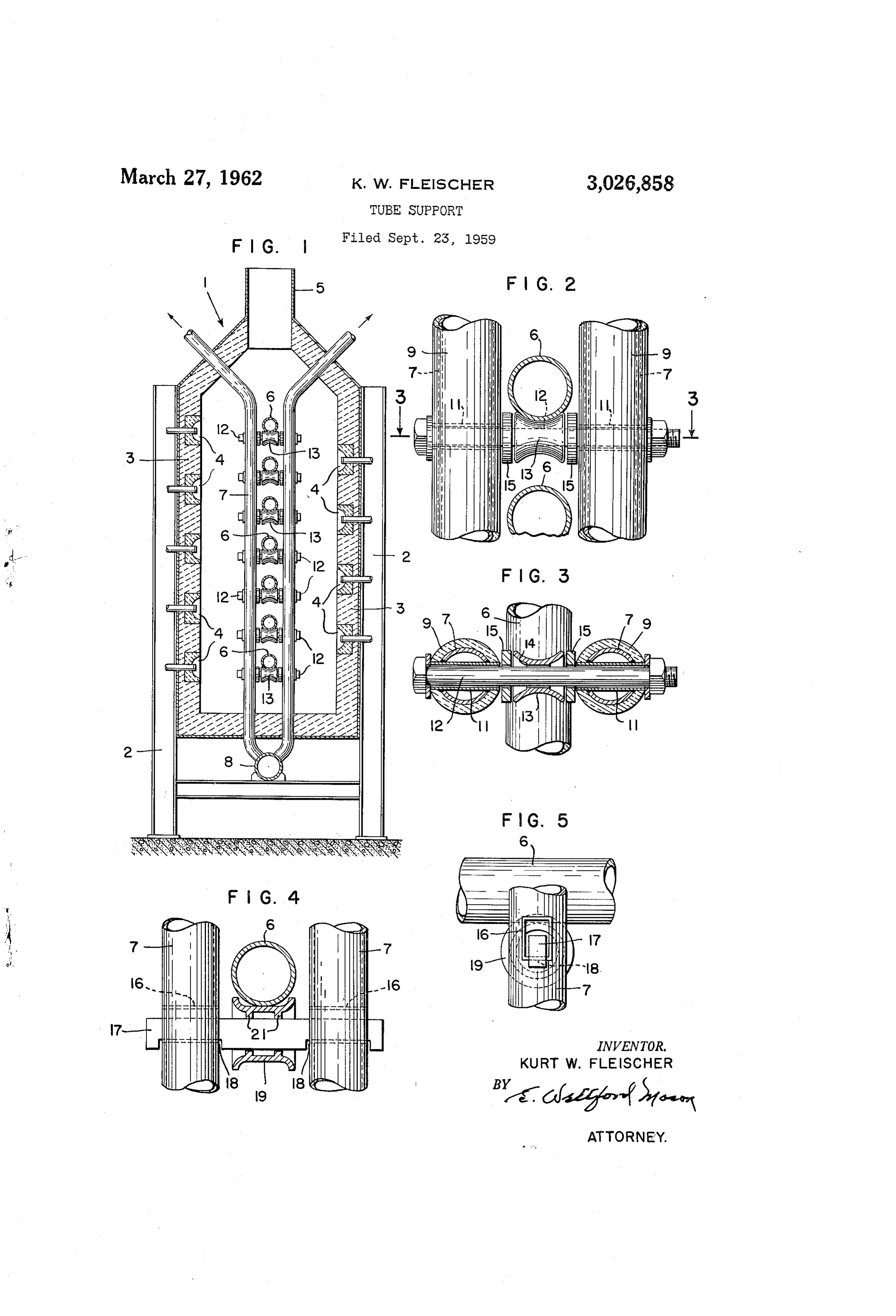
The present invention relates to furnaces for heating are supported along their length at frequent enough inter fluids flowing through tubes, and more particularly to a 0. vals so that they will not sag during the heating process. Support for holding the tubes in such a furnace. For normal furnace practice these supports would be In tube heating furnaces of the type used in the petro about eight feet apart.
leum and chemical industries the tubes are frequently Referring to FIGS. 2 and 3 it will be seen that the from thirty to fifty feet in length. These tubes must pipes 7 can be covered with insulation 9, if it is so be supported in the furnace in such a manner that they 5 desired. Generally this is done in order to prevent too will not sag or become distorted with the heat, and in much heat from the furnace being carried away by the such a manner that they are permitted to expand and cooling fluid flowing through the pipes. contract with changes in temperature. The pipes 7 are provided with horizontally extending It is an object of the invention to provide a means and aligned openings through which are inserted sleeves for Supporting a tube in a furnace which will retain its 20 11 with the ends of the sleeve being welded to the edges strength under the high temperatures that are en of the openings in the pipe to form a liquid tight joint countered, and one which will permit expansion and between the two. The sleeves form vertically spaced, contraction of the tube without damage thereto. aligned passages through each pair of which a shaft in In carrying out the invention, vertically extending, the form of a bolt 12 extends. Each shaft has on it, Water-cooled supports are located at spaced points along 25 between pipes 7, a tube supporting roller 13 that has a furnace. The supports are such that horizontally a reduced bearing portion 14. Spacers i5 may be, and extending tubes are located at fixed levels in the furnace, preferably are, used between the inner ends of sleeves with the tubes being free to expand, without damage to 1 and the roller 13 in order to maintain the roller in themselves, as a result of temperature changes. the center of the shaft. These shafts and the rollers The various features of novelty which characterize my 30 thereon are located at spaced points along the pipes 7 invention are pointed out with particularity in the claims to support the tubes 6. If the tubes 6 are five inches annexed to and forming a part of this specification. in diameter, the supports can be placed on ten inch For a better understanding of the invention, however, centers, thus giving plenty of room between the supports its advantages and specific objects attained with its use, for the tubes to be inserted. - reference should be had to the accompanying drawings With a tube support of the type shown herein, cooling and descriptive matter in which I have illustrated and fluid flowing through pipes 7 and around sleeves A, described a preferred embodiment of the invention. will keep these parts at a temperature sufficiently low In the drawings: So that they will have strength enough to support the FiG. 1 is a section through a tube heating furnace 40 tubes in their desired locations. Since the shafts 2 showing the support of the invention, extend through the water cooled sleeves 1, they will FiG. 2 is an enlarged view of one of the tube supports, also be cooled sufficiently for them to retain their FIG. 3 is a view taken on line 3-3 of FIG. 2, strength in the heat of the furnace. Rollers i3 will be FIG. 4 shows a modified form of tube support, and made of a heat resisting alloy that is capable of with FIG. 5 is a view taken from the right of FIG. 4. standing the temperature that is encountered. The bear Referring to the drawings, there is shown in FIG. 1 a 45 ing portion 14 of this roller has a loose fit on shaft 2 section through a tube heating furnace similar to that so that as the pipe resting thereon expands and contracts, disclosed in Hess Patent 2,638,879. This furnace in the roller will rotate with a minimum of friction on cludes buskstays 2 that are used to support the structure the shaft, thereby permitting the tube to expand and of the furnace which may be built of refractory mate 50 contract freely without the tube itself being scraped rial backed up by sheet metal in accordance with ordinary against any surface.
furnace practice. The furnace is shown as including The embodiment of the invention disclosed in FGS. 4 side walls 3 that have located at spaced points in the and 5 differs from that previously disclosed primarily burners 4. The upper portion of the furnace terminates in the manner in which the tube supporting roller is in the stack 5. Tubes 6, through which the fluid to be 55 mounted between the pipes 7. It will be seen from the heated flows, extend horizontally in a direction perpen drawings that passages are formed in pipes 7 by rectangu dicular to the plane of the drawing. The ends of the lar sleeves i6 which extend through the pipes and which lengths of tube are usually joined by return bends to form have their ends welded to openings provided in the pipes. a continuous, serpentine tube through which the fluid A substantially rectangular bar i7 having cut-out por to be heated flows back and forth across the length of tions 18 extends between the parallel pipes 7 with the the furnace from the top to the bottom thereof. Nor 60 cut-out portions or notches resting against the lower mally the return bends at one end of the tube bank are side of sleeves 6. With this arrangement a bar 7 held stationary so that as the tubes expand and contract can be moved into position and will remain properly due to changes of temperature in the furnace chamber, located because of the cut-out portions. Received on they will move toward and from that end of the furnace. 65 this bar, between the pipes 7, is a tube supporting roller With a conventional arrangement of this type, it is neces É9 which is provided with a pair of narrow bearing sary to provide means for supporting the tube lengths in portions 21 that rest against the top of the bar, which parallel relation as they extend horizontally through the may have a curvature equal to that of portions 21. furnace, and to provide some means that is capable In this case also the bar 17 is cooled by its engage of permitting movement of the tubes without damage 70 ment with sleeve 16 so that the bar is maintained at a to them. - temperature low enough for it to retain its strength. The tube support with which this invention is par The relatively small bearing surface between the por ticularly concerned comprises a pair of vertically extend tions 2i of the roller and the upper surface of bar 17
Page 3
will permit this roller to rotate freely as the tubes 6 will engage the ends of said passages to prevent move carried thereon expand and contract. ment of said members, and in which said element are From the above description it will be seen that I have rollers received on said members. provided a tube support consisting of parallel, vertically 4. Means for supporting a tube adapted to extend extending water-cooled pipes, which pipes are provided 5 horizontally in a furnace chamber comprising a pair of with sleeves that serve to keep the tube supporting mem parallel, vertically extending pipes, each of said pipes ber at low enough temperature so that its strength will being provided with a pair of horizontal openings with not be impaired. In addition, the tube itself is sup the openings in the pipes being axially aligned, a sleeve ported on rollers that can be rotated when the tube extending through each pipe and received in each pair changes in length. Since the rollers which actually sup 10 of openings to form a passage, means to supply a cool port the tube are themselves not cooled to any appreci ing fluid to flow through said pipes and around said able extent, they will not have a cooling effect on the passages, a supporting member extending through said tube or the fluid flowing therethrough. passages, an element upon which a tube is adapted to While in accordance with the provisions of the statutes, rest mounted for rotation on said member between said I have illustrated and described the best form of embodi plpes.
ment of my invention now known to me, it will be 5. The combination of claim 4 in which said tube apparent to those skilled in the art that changes may be supporting member is in the form of a grooved roller. made in the form of the apparatus disclosed without 6. A tube support for use in a furnace having hori departing from the spirit and scope of the invention set Zontally extending tubes comprising a pair of vertically extending pipes, means to supply a cooling fluid through forth in the appended claims, and that in some cases 20 said certain features of my invention may be used to advan pipes, a plurality of vertically spaced pairs of open tage without a corresponding use of other features. ings in said pipes, the openings in each pipe being hori What is claimed is: Zontally aligned with a pair of openings in the other 1. Means for supporting a bank of tubes adapted to pipe, sleeves forming passages extending through each extend horizontally in a furnace chamber comprising a pipe with a sleeve received in each pair of openings, pair of parallel pipes extending vertically, each pipe a supporting member extending through said aligned pas having a plurality of vertically spaced pairs of axially Sages, means to hold said members against axial move aligned openings extending horizontally therethrough, a ment in said passages and a tube carrying part on each sleeve forming a horizontal passage through the pipe 30 member between said pipes.
and received in each pair of openings, means to Supply 7. The combination of claim 6 in which said pipes a cooling fluid through said pipes and around said are insulated.
passages, the passages in each pipe being aligned hori 8. The combination of claim 7 in which each tube Zontally with a passage in the other pipe, a supporting carrying part is a roller loosely received on a supporting member received in and extending through each pair of member.
aligned passages, and a tube supporting element Sur rounding each member between said pipes. References Cited in the file of this patent 2. The combination of claim 1 in which each of said UNITED STATES PATENTS passages is cylindrical and said supporting member is a 425,856 Bristin --------------- Apr. 15, 1890 shaft, each element being a grooved roller rotatable on 40 1,645,762 Lohbiller ------------- Oct. 18, 1927 said shaft. 2,103,811 Davis ---------------- Dec. 28, 1937 3. The combination of claim 1 in which each passage 2,652,037 Lewis et al. ---------- Sept. 15, 1953 is rectangular in shape and each supporting member is 2,716,968 Hess et al. ------------ Sept. 6, 1955 correspondingly shaped and of a size to be received in said passages, said members being provided on their FOREIGN PATENTS lower surfaces with notches of a length equal to the 503,639 Canada -------------- June 15, 1954 length of said passages whereby the ends of said notches
Provenance
- Collection
- Cited prior art
- Original PDF
- patentimages.storage.googleapis.com →
- Filed
- 1959-09-23
- Pages
- 3
- Method
- pdftotext (the PDF's own text layer) + pdftoppm 300dpi page scans
- Source
- Google Patents bibliographic record
- Granted
- 1962-03-27
- Inventors
- Kurt W Fleischer; Selas Corp of America
- Transcribed from
- patentimages.storage.googleapis.com →