patent · US5417052
Hybrid solar central receiver for combined cycle power plant
23 May 1995
Page 1 — bibliographic record
O USOO5417052A United States Patent 19 11 Patent Number: 5,417,052 Bharathan et al. 45 Date of Patent: May 23, 1995 54 HYBRID SOLAR CENTRAL RECEIVER FOR 4,189,922 2/1980 Bellofatto.............................. 60/641 COMBINED CYCLE POWER PLANT 4,259,836 4/1981 Finckh.
75 Inventors: Desikan Bharathan, Lakewood; 4,466,423 8/1984 Dolan et al. . Mark S. Bohn, Golden; Thomas A. 4,509,333 4/1985 Nussdorfer et al. ............... 60/203.1 Williams, Arvada, all of Colo. 4,727,930 3/1988 Bruckner et al. .............. 165/104.17
73 Assignee: Midwest Research Institute, Kansas 4,942,736 7/1990 Bronicki ........................... 60/64.2 City, Mo.
FOREIGN PATENT DOCUMENTS
22 Filed Nov. 5, 1993 105606 8/1979 Japan ................................ 60/641.14 16Ci: Ov. 5, Primary Examiner-Louis J. Casaregola Int. C. ................................................ F02C 6/00 Attorney, Agent, or Firm-Edna M. O'Connor 52 U.S. Cl. .................................. 60/39.02; 60/39.33;
60/641.65/104.15 57 ABSTRACT 58 Field of Search ............... 60/39.02, 39.182, 39.33, A hybrid combined cycle power plant including a solar 60/641.8, 641.12, 641.14, 641.15, 689; central receiver for receiving solar radiation and con 165/104.11, 104.15, 104.17, 104.19, 104.21, verting it to thermal energy. The power plant includes 104.26 a molten salt heat transfer medium for transferring the thermal energy to an air heater. The air heater uses the (56) References Cited thermal energy to preheat the air from the compressor
4,067,315 1/1978 Fehliner et al. ................. so are directed to a steam turbine for additional energy 4,094,148 6/1978 Nelson . production.
4,167,856 9/1979 Seidel et al. ....................... 60/39.33 13 Claims, 1 Drawing Sheet
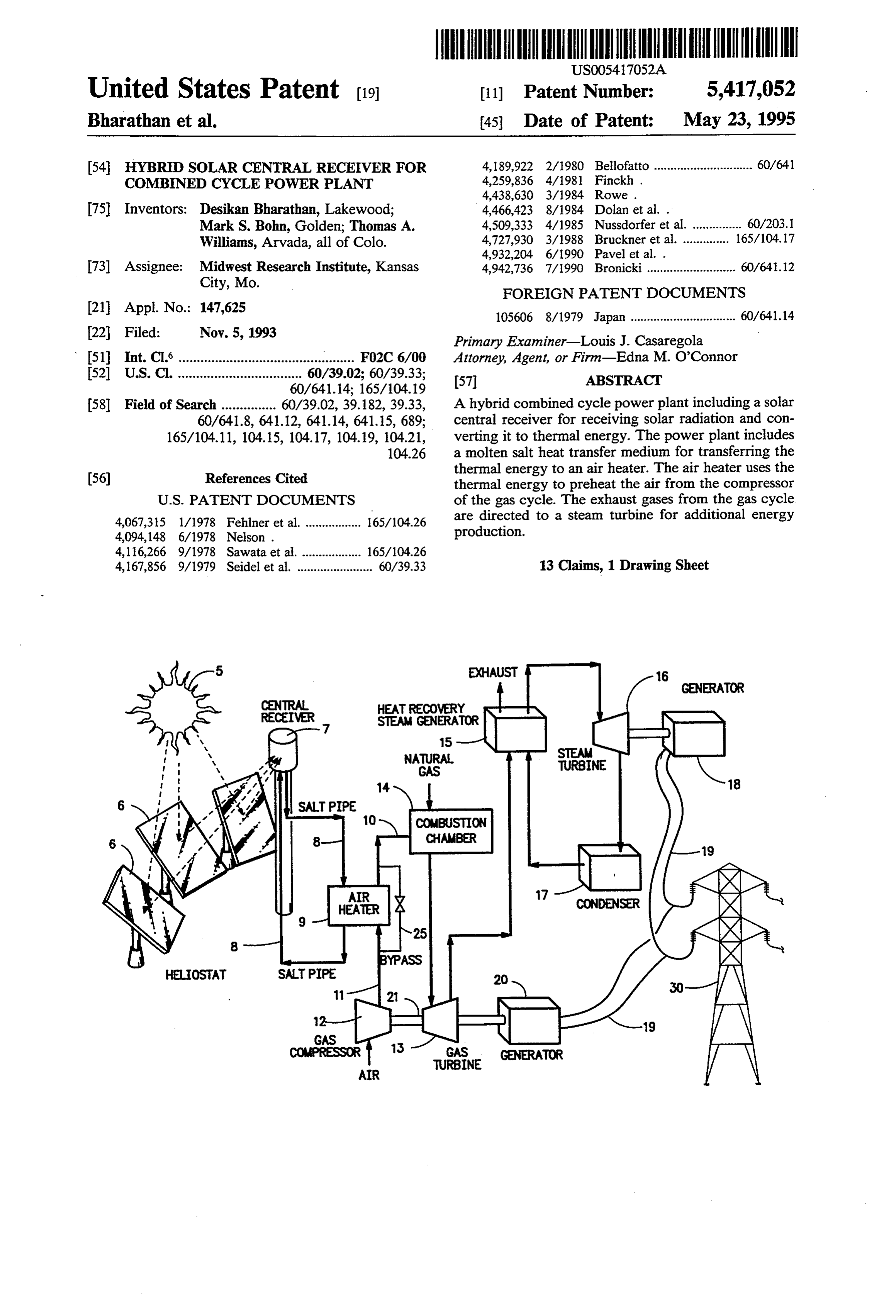
GENERATOR
CENTRAL
RECEIVER SEEor NRN MY
CFR
GAS
SALT PIPE
CHAWBER
CXD
HELIOSAT SALT PIPE
1 HR 24- E\
Page 2
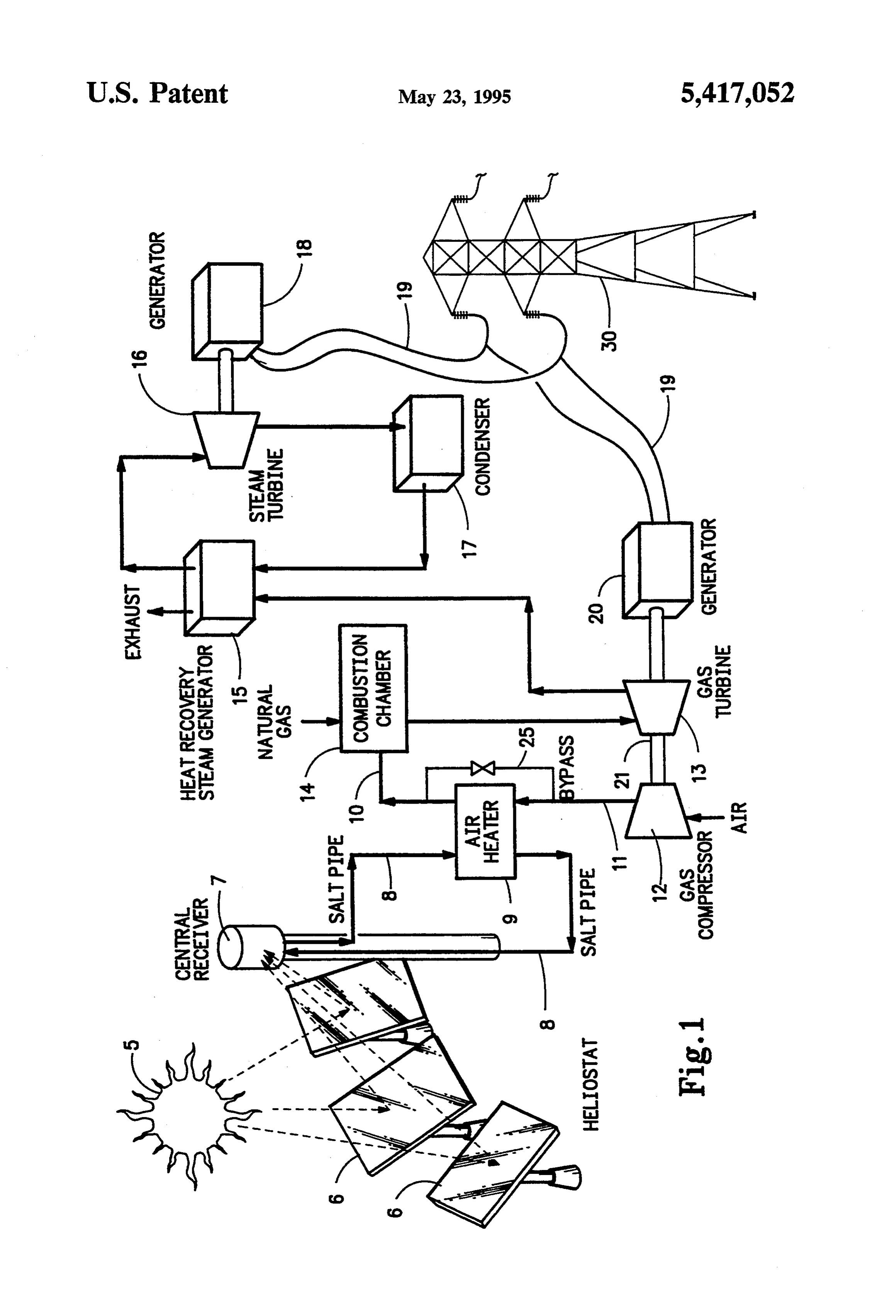
Drawing sheet — no readable text.
Page 3
air preheater is also required to preheat the air before it
HYBRD SOLAR CENTRAL RECEIVER FOR is directed into the compressor.
COMBINED CYCLE POWER PLANT Another example of utilizing solar heat to preheat the air prior to combustion is shown in U.S. Pat. No.
CONTRACTUAL ORIGIN OF THE INVENTION 5 4,259,836 to Finckhet al. As described by this patent, The United States Government has rights in this the solar energy function can be selectively discon invention under Contract No. DE-AC02-83CH10093 nected from the gas turbine for conventional operation. between the U.S. Department of Energy and the Na Again the reference refers to direct preheating without tional Renewable Energy Laboratory, a Division of O the use of a central receiver and heat transfer medium. Midwest Research Institute. Also, the reference is not directed to a combined cycle power plant.
BACKGROUND OF THE INVENTION In the past, molten salt has been used as a heat trans The instant invention relates to the use of a hybrid fermedium. For such a use the temperature of the mol central receiver with a natural gas combined cycle ten salt is kept sufficiently high to keep the salt in its power generating system. The system of the instant 15 molten form, generally above 500 F. Both U.S. Pat. invention uses solar energy to supplement the operation No. 4,094,148 to Nelson, and U.S. Pat. No. 4,438,630 to of the natural gas combined cycle system by using the Rowe disclose the use of molten salt for heat transfer solar generated heat to preheat the combustion air. The purposes. Neither of the references however, discloses Solar generated heat is transferred to the natural gas using molten salt to transfer heat from a solar central cycle by an air/molten salt heat exchanger or air heater. 20 receiver. Nelson uses the salt to store heat released by Combined cycle power plants which include a steam exhaust gases derived from the combustion of gaseous turbine to utilize waste heat from the gas turbine are products in a coal gasification process so that the en well known. Typically such a plant includes a combus ergy can be utilized to generate increased electrical tion turbine driving an electric generator, a heat recov power during peak demand periods. The Rowe refer ery steam generator which receives exhaust gas from 25 ence is directed to a co-generating steam supply system the combustion turbine, and a steam turbine driven by which utilizes a molten salt heat transfer fluid for utiliz Superheated steam for driving another electrical genera ing the steam produced by the first unit for maintaining tor or for achieving other well known functions. The selected steam turbine is located in a closed loop connecting the ond unitcomponent during operating temperatures in the sec periods when the second unit is not inlet and outlet of the heat recovery steam generator. 30 producing steam. The transporting of heat from a cen Such a combined cycle power plant is shown in U.S. tral receiver is not mentioned by either of the refer Pat. No. 4,932,204 to Pavel et al. eCeS.
The Pavel et al patent, however is not concerned Central receiver power systems are capable of gener with the use of a central receiver or the use of solar energy to preheat the air supplied to a combustion tur 35 ating large amounts of electrical energy. To provide bine. Rather, the patent adjusts the flow rate of feed such power, central receiver systems usually include an water through an economizer section of a heat recovery array of thousands of individually steered flat reflectors steam generator to provide an excess flow which is used or mirrors and a central receiver on top of a tower. to preheat the fuel delivered to a combustion turbine. Such arrays are normally referred to as a heliostat field, Solar thermal central receiver power plants are also while the individual reflectors are normally referred to well known. Such power plants are large and currently as heliostats. The heliostat field redirects radiant solar costly to build, and thus such technology has not car energy to the receiver. The receiver collects and con ried forth into development on a commercial scale. verts the radiant solar energy to thermal energy. Such a Designs for such plants have been known to use a cen system is disclosed in U.S. Pat. No. 4,466,423 to Dolan tral receiver which has the potential to be a very cost 45 et al.
effective solar technology for generating electricity. The instant invention makes it possible to use a cen The most preferred well known central receiver design tral receiver on a smaller scale than that contemplated utilizes a tube-type receiver, molten salt as a heat trans for production solely through the use solar energy fermedium, and a steam turbine to convert the absorbed while still achieving enhanced energy production with heat into electricity. Such a system is extremely expen 50 associated cost savings.
sive to build and will result in relatively high energy SUMMARY OF THE INVENTION costs. The known system designs do not contemplate using a central receiver in a hybrid plant having a high It is an object of the instant invention to provide a efficiency combined cycle (a gas turbine plus a steam power plant utilizing solar energy which is commer turbine to utilize waste heat from the gas turbine). 55 cially advantageous to build. A solar thermal power plant is also described in U.S. It is a further object of the instant invention to pro Pat. No. 4,167,856 to Seidel et al. This patent discloses vide a hybrid, (gas powered with solar assist), power an open air circuit wherein the effective heat obtained plant which recognizes the current cheapness of fossil from solar energy is supplied to the air flow between a fuels while allowing for future solar expansion. compressor and an expansion machine. This power It is an additional object of the invention to provide a plant utilizes a solar heater exposed directly to solar solar central receiver to produce sufficiently high tem radiation. Thus the use of a heat transfer medium such peratures for use in a high efficiency combined cycle as molten salt is not contemplated. Also, the reference is power plant.
not directed to a combined cycle plant configuration It is a further object of the invention to provide a nor does it recognize that such a combined cycle plant 65 power plant with selective solar input which reduces would result in cost savings when utilized with a central the amount of natural gas required for plant operation. receiver. The reference does use the solar heater to The instant invention relates to a combined cycle directly heat air prior to combustion, but an additional power plant with a hybrid central receiver. The power
Page 4
plant includes a gas turbine for driving a first electric wires 19 and towers 30 or by other well known distribu generator for producing electrical power, and a steam tion methods.
turbine operated off the exhaust gases of the gas turbine For efficient use of a combined cycle plant it is desir for driving a second electric generator for producing able that sufficiently high temperatures be achieved to additional electric power. The gas turbine portion of 5 have waste heat that is utilized by the steam turbine. the combined cycle plant includes a combustion cham The instant invention achieves sufficient waste heat ber or generator for heating air and fuel provided to the from the gas turbine to utilize the highly efficient com turbine section, and a gas compressor for compressing bined cycle configuration. A solar powered combustion the air provided to the combustion chamber. An air air preheater between the gas turbine cycle compressor heater is provided between the compressor and the 10 and combustion chamber provides heat which is used in combustion chamber. The air heater derives the thermal both the gas turbine and in the steam generator. The energy used to heat the air from a central receiver solar powered combustion air preheater further which receives solar radiation from the sun which radi achieves improved fuel efficiencies for the combined ation is reflected to the receiver by a heliostat array. cycle of the plant by providing solar heated combina The solar radiation is converted to thermal energy by 15 tion air preheat.
the central receiver. The thermal energy is transferred The air preheater of the instant invention includes a to the air heater through the use of a molten salt transfer heliostat collector comprising individual heliostats or medium. That is, the central receiver heats the salt in its reflectors 6, each individually steered for rotation about molten state as it passes in tubes or pipes through the its respective elevational axis and azimuthal axis to receiver. The tubes conduct the molten salt to the air 20 track the sun 5. The heliostats or reflectors 6 direct the heater where the thermal energy is used to heat the air received solar radiation to a tube-type or other well therein. This preheating of the air results in fuel efficien known central receiver 7 which is typically mounted on cies as well as providing sufficient heat for combined a tower 4. The receiver 7 collects and converts the cycle operation. radiant solar energy to thermal energy, as is well The invention further contemplates the method of 25 known, and such thermal energy heats salt contained in utilizing solar energy in a combined cycle plant along pipes or tubes 4. The resulting molten salt is used as a with a fluid heat transfer medium. heat transfer medium.
BRIEF DESCRIPTION OF THE DRAWING The heat transfer medium preferably uses a nitrate salt, such as sodium nitrate or potassium nitrate al
FIG. 1 is a block diagram showing the power plant of 30 though carbonate salts, such as sodium carbonate, po the instant invention. tassium carbonate or lithium carbonate can be used. A DESCRIPTION OF THE PREFERRED molten metal such as sodium metal can also be used as EMBODIMENT the fluid heat transfer medium. The receiver supplies molten salt in a range from 500-1100 F. for nitrate
FIG. 1 shows a typical combined cycle power plant 35 salts or in a range from 750-1650 F. for carbonate salts with the additional features for added fuel efficiencies in to a combustion preheater or air heater 9 between the accordance with the instant invention. The combined gas turbine cycle compressor 12 and combustion cham cycle power plant includes a gas turbine section 13 of a ber 14.
gas cycle, a heat recovery steam generator 15, and The air in the air heater 9 can be heated by the molten steam turbine 16. The gas compressor 12 of the gas 40 salt by indirect or direct contact by any well known cycle is coupled to the gas turbine section 13 by means method, but in the preferred embodiment a simple of shaft 21. The gas turbine 13 is coupled to drive an tinned heat exchanger is used. That is, the molten salt electric generator 20 to produce electrical power which remains inside the transfer tubes while the air to be is disseminated through distribution wires 19, carrier heated is located outside the tubes. The heat from the towers 30, or other well known means. The gas com- 45 molten salt is transferred through the tubes to the air. pressor 12 receives ambient air from an air inlet as This preheated air is then directed through ducting 10 shown. A combustion chamber 14 heats compressed gas to the combustion chamber or generator 14. The addi from the gas compressor and supplies it to the turbine tion of the preheated air reduces the amount of natural section 13 in a known manner. The combustion cham gas which is required by the gas combustion chamber. ber receives natural gas as fuel as shown. 50 However, the combined cycle system can still operate The instant invention is further directed to the addi without the air preheating for maximum flexibility of tion of an air heater 9 along with suitable heat transfer operation. A bypass pipe 25 with associated valves as is medium, to conduct thermal energy between a solar well known, is provided around the air heater so that central receiver and the air heater. These features will the plant can operate at maximum efficiency during be referred to in greater detail later in the description. 55 periods when the solar heat is not available. The heat recovery steam generator 15 receives excess The combined system of the instant invention has heat from the gas turbine 13 in the form of hot exhaust distinct and important advantages over an exclusively gases. As is well known in the art, the heat recovery solar system. The first advantage is that the central steam generator 15 typically includes three heat ex receiver will not have to be built on such a large scale change sections, a superheater section, an evaporator 60 since combined-cycle equipment is economic in smaller section, and a preheater section each with an inlet and sizes as compared to steam turbine equipment alone. an outlet. As is well known, exhaust gases flow over the For example, a viable stand-alone solar system would superheater section, then over the evaporator section require almost twenty times as many heliostats as the and lastly over the preheater section. Additional heat combined system of the instant invention. This would exchange sections may also be provided. Superheated 65 result in considerable construction savings as well as steam is directed through the steam turbine 16 which savings as to energy costs per kilowatt hour. drives electrical generator 18. Electrical power pro The system of the instant invention also takes advan duced from the generator 18 is distributed through tage of the relative cheap cost of natural gas while
Page 5
preparing for increased use of solar technology in the g) transferring the molten salt medium to the air event the cost for such gas increases. heater to heat the air in the air heater; Also, the system of the instant invention uses inexpen h) transporting the heated air to a combustion cham sive salts although molten metal can be used. The mol ber to mix the preheated air with fuel for operating ten salt is a very good heat transfer medium, thus per the gas turbine.
mitting the central receiver and air heater to be small in 7. The method of claim 6 wherein the gas turbine size. The salt also has low vapor pressure, which mini produces exhaust gases and further comprising the step mizes corrosion if the proper temperature range is main of transporting such exhaust gases to a steam turbine for tained. additional electric power production. The foregoing description is considered as illustrative 10 8. In a combined cycle power plant having a gas only of the principles of the invention. Further, since turbine cycle with a combustion chamber, and a steam numerous modifications and changes will readily occur to those skilled in the art, it is not desired to limit the turbine, which receives the exhaust gases of the gas turbine, the improvement comprising invention to the exact construction and processes shown as described above. Accordingly, all suitable 15 a) the a central receiver for receiving solar radiation from sun and converting the solar radiation to ther modifications and equivalents may be resorted to falling mal energy;
within the scope of the invention as defined by the b) an air heater for heating air before it enters the claims which follow.
We claim: combustion chamber of the gas turbine cycle; and 1. A hybrid combined cycle power plant comprising c) a liquid medium for comprising molten salt for a) a gas cycle comprising a gas turbine section for conducting the thermal energy from the central driving a first electric generator for producing receiver to the air heater, wherein such thermal electrical power, said gas turbine section produc energy is used to heat the air in the air heater before ing exhaust gases, a combustion chamber for heat it enters the combustion chamber of the gas turbine ing air provided to the gas turbine section, and a 25 cycle.
gas compressor for compressing air provided to the 9. In the combined cycle power plant of claim 8 fur combustion chamber, and means for conducting ther comprising a plurality of heliostats for directing compressed air from the gas compressor to the solar radiation from the sun to the central receiver. combustion chamber, 10. A hybrid power plant comprising b) a steam turbine operated off the exhaust gases of 30 a) a gas turbine system having a gas compressor, a the gas turbine for driving a second electric genera combustion chamber, and a gas turbine connected tor for producing electrical power, to a generator for electrical power production c) an air heater for heating the air as it is conducted wherein said gas compressor compresses intake air between the gas compressor and the combustion transported to the combustion chamber, and the chamber, 35 combustion chamber mixes and combusts the air d) a central receiver for generating thermal energy in plus intake fuel for operation of the gas turbine; response to radiation received from the sun; and b) an air heater between the combustion chamber and e) a liquid heat transfer medium comprising molten the compressor to heat the compressed air from the salt for transferring the thermal energy produced compressor;
by the central receiver to the air heater to heat the c) a central receiver for receiving solar radiation from air between the gas compressor and the combus the sun and converting the solar radiation to ther tion chamber. mal energy;
2. The powerplant of claim 1 further comprising tube d) a liquid transfer medium comprising molten salt for means to conduct said molten salt from said central transferring the thermal energy from the central receiver to said air heater and back to said central re 45 receiver to the air heater, wherein the air in the air ceiver.
3. The power plant of claim 2 wherein said tube heater is heated by the transferred thermal energy from the central receiver.
means containing said molten salt passes through said 11. The hybrid power plant of claim 10 further com air heater to heat the air contained therein.
4. The power plant of claim 1 wherein said molten 50 prising a plurality of heliostats to direct the solar radia tion to the central receiver.
salt is at a temperature from 500 to 1650 F.
5. The power plant of claim 1 further comprising a gas12.turbine The hybrid power plant of claim 10 wherein said produces exhaust gases and further compris plurality of heliostats to reflect the radiation from the ing sun onto the central receiver.
6. A method of operating a hybrid power plant com 55 a) a heat recovery steam generator for receiving the prising the steps of exhaust gases from the gas turbine and a steam a) providing a gas turbine for driving an electric turbine connected to the heat recovery steam gen generator for production of electrical power; erator for producing additional electrical power. b) providing a solar central receiver; 13. A hybrid combined cycle power plant comprising c) providing a plurality of reflecting surfaces to direct 60 a) a gas cycle comprising a gas turbine section for solar radiation from the sun to the central receiver; driving a first electric generator for producing d) converting the solar radiation received by the electrical power, said gas turbine section produc central receiver into thermal heat; ing exhaust gases, a combustion chamber for heat e) providing a molten salt liquid heat transfer medium ing air provided to the gas turbine section, and a to transfer the thermal energy from the central 65 gas compressor for compressing air provided to the receiver to an air heater; combustion chamber, and means for conducting f) providing the air heater with compressed air from compressed air from the gas compressor to the an air compressor; combustion chamber.
Page 6
b) a steam turbine operated off the exhaust gases of d)response a central toreceiver for generating thermal energy in radiation received from the sun; and the gas turbine for driving a second electric genera e) A liquid heat transfer medium comprising metal in tor for producing electrical power, its molten state for transferring the thermal energy c) an air heater for heating the air as it is conducted produced by the central receiver to the air heater wherein the molten meatal heats the air between between the gas compressor and the combustion the gas compressor and the combustion chamber. chamber, sk i k is ak
Provenance
- Collection
- Cited prior art
- Original PDF
- patentimages.storage.googleapis.com →
- Filed
- 1993-11-05
- Pages
- 6
- Method
- pdftotext (the PDF's own text layer) + pdftoppm 300dpi page scans
- Source
- Google Patents bibliographic record
- Granted
- 1995-05-23
- Inventors
- Desikan Bharathan; Mark S. Bohn; Thomas A. Williams; Midwest Research Institute
- Transcribed from
- patentimages.storage.googleapis.com →