patent · US4727930
Heat transfer and storage system
1 March 1988
Page 1 — bibliographic record
United States Patent (19) 11 Patent Number: 4,727,930 Bruckner et al. (45) Date of Patent: Mar. 1, 1988 (54) HEAT TRANSFER AND STORAGESYSTEM Hydrate Latent Heat and Direct Contact Heat Exchan (75) Inventors: Adam P. Bruckner, Seattle; Abraham ge-1, Solar Energy, vol. 25, pp. 437-444, 1980. Hertzberg, Bellevue; David J. Shaw,
Seattle, all of Wash. Primary Examiner-Albert W. Davis, Jr.
73) Assignee: The Board of Regents of the Attorney, Agent, or Firm-Christensen, O'Connor, Johnson & Kindness
University of Washington, Seattle,
Wash.
An energy storage and conversion system utilizes (22 Filed: Aug. 17, 1981 unique heat exchange media for storing and transferring 51) Int. Cl."......................... F28C3/14: F28D 19/02 heat. In one embodiment, a refractory material is heated 52 U.S. C. ................................... 165/1; 165/104.17; to the molten state by a solar furnace. The refractory 165/111; 165/84 material is stored in its molten form and metered to a 58) Field of Search ...................... 165/111, 104.17, 1, direct-contact heat exchanger. It is fed into the heat 165/84 exchanger in a plurality of streams that break into a (56) References Cited plurality of droplets. The droplets flow through the heat exchanger in countercurrent relationship with a
3,185,457 5/1965 Boll et al.................... 165/104.17 X heated and expanded through an expansion engine to OTHER PUBLICATIONS convert the thermal energy to mechanical energy which in turn can be utilized to produce electricity, for
Nichols, M. C. et al., Direct Contact Heat Exchange for example. The refractory can be sufficiently cooled in Latent Heat-of-Fusion Energy Storage Systems, Pro the heat exchanger to fuse into beads, which can be ceedings of Miami International Conference on Alter easily recycled to the solar furnace. native Energy Sources, Miami Beach Fla., pp.
Fouda, A. E. et al., Solar Storage Systems. Using Salt 7 Claims, 5 Drawing Figures
svaaa
catafa
Page 2
Drawing sheet — no readable text.
Page 3
Drawing sheet — no readable text.
Page 4
Drawing sheet — no readable text.
Page 5
Drawing sheet — no readable text.
Page 6
Drawing sheet — no readable text.
Page 7
the replacement costs of the capacitive elements be
HEAT TRANSFER AND STORAGE SYSTEM come increasingly acute as higher temperatures and larger rates of temperature change are encountered.
BACKGROUND OF THE INVENTION
SUMMARY OF THE INVENTION
This invention was developed in part during work 5 conducted under and supported by NASA research In accordance with the present invention, it has been grant NAG 3-16, as well as by a grant from the Univer found that classical inefficiencies of prior capacitive sity of Washington Graduate School Research Fund heat exchangers can be overcome by providing capaci awarded through the Washinton Energy Research Cen 10 tive elements that are mobile and that are remanufac ter. tured during each temperature cycle. In this manner, Achieving effective heat transfer is one of the princi degradation of solid-phase capacitive elements due to pal problems facing the designers of efficient energy thermal shock is eliminated. Additionally, by employ conversion systems for almost any application today, ing liquid-phase capacitive elements, an energy storage ranging from today's coal combustion systems to ad 15 system can become an integral part of a heat exchange vanced fusion power and solar energy extraction sys system. More importantly, the energy storage system tems. Ideally, a heat exchanger should be operated at associated with such capacitive elements can be high temperatures matching the thermodynamic potential of enough to maximize the thermodynamic potential of a the peak temperatures of the system heat source. Con heat source. Moreover, the energy storage capability ventional heat exchangers, however, are rarely able to 20 allows a system utilizing the present invention to be match that potential, severely limiting the capability of operating at desirable temperatures. Furthermore, continuously
In its operated under optimum conditions.
broadest sense, the present invention provides a when operating to recover heat at lower temperatures method for exchanging in a heat transfer system, large pressure drops are re exchange medium and heat between a first liquid heat quired by small temperature differentials, leading to medium by first causing a first heat fluid a second heat exchange exchange medium to correspondingly higher costs of heat transfer and con 25 traverse a heat transfer zone in the form of droplets, and comitant inefficiencies.
Another problem in achieving efficient energy con to simultaneously causing a second heat exchange medium version systems relates to the storage of energy. Energy traverse the heat transfer zone in countercurrent flow storage is of benefit to the operation of central power relationship to the first heat exchange medium, while stations, for example, by providing a means of matching 30 allowing the first and second heat exchange media to periodically varying loads to the uniform output desir make intimate thermal contact with each other. In a able to operate a powerplant most efficiently. For exam preferred form of the invention, the second heat ex ple, an efficient and economical energy storage system change medium comprises a gas. Preferably too, the must be an integral part of the design of a solar power first heat exchange medium is injected into the heat plant because of the intermittent nature of the solar 35 transfer zone as a liquid stream that is sized to cause the energy resource. Few presently suggested solar power stream to break into a plurality of droplets as it is enter systems directly integrate energy storage into the pow ing the heat transfer zone. The first heat transfer me erplant design. Often, with the prior designs, waste heat dium is preferably cooled from the liquid phase to the from a primary cycle is stored, and then used at low solid phase before it is removed from the heat transfer temperatures in less efficient bottoming cycles. When zone, thus, allowing the first heat transfer medium, that energy storage is provided for use in the primary cycle, is, the capacitive elements, to be handled as a solid. such as in a liquid sodium energy storage system, heat Very high operating temperatures can be achieved by must still be transferred through a heat exchanger. Such using a refractory oxide as the first heat transfer me storage sytems, however, are expensive. Additionally, dium.
currently available heat exchanger materials severely 45 A direct-contact heat exchange system employing the limit working temperatures. broad method of heat transfer includes a container High-temperature heat storage facilities and heat means defining a heat transfer chamber. A first inlet transfer devices are essential to economically attractive means is associated with the container means for intro central power stations such as solar energy power ducing the first heat exchange medium into the chamber plants. For example, promising power generation cy 50 a plurality of liquid droplets. A first outlet means is cles with efficiencies ranging from 45% to 70% can be as achieved at the peak temperatures of up to 2000 K. It associated the first with the container means and is spaced from inlet means for removing the first heat ex has been suggested that capacitive heat exchangers might be employed to exploit the more efficient, higher change medium from the chamber. A second inlet temperature regimes because they circumvent some of 55 means is associated with the container means and is spaced from the first inlet means in the direction of the the limitations of conventional tube wall heat exchang first ers. Capacitive heat exchangers and storage systems can outlet means. The second inlet means introduces th use high-temperature materials and transport those ma second fluid heat exchange medium into the chamber. A second outlet means is associated with the container terials into direct contact with a heat source. Common examples of conventional capacitive heat exchangers means and is spaced from the second inlet means in the are packed bed regenerative heat exchangers and fluid direction of the first inlet means. The second outlet ized bed heat exchangers. However, conventional ca means removes the second heat exchange medium from pacitive heat exchangers also suffer from serious draw the chamber. Of course, the first and second heat ex backs in that the solid phase capacitive elements, which change media must be immiscible with each other. Ad must operate in a cyclic fashion, are subject to physical 65 ditionally, the inlet and the outlet means must be con degradation resulting from thermal shock. Since the structed and arranged relative to the chamber so that solid phase capacitive elements represent a high fraction the heat exchange media will be placed in intimate ther of the total system cost of capactive heat exchangers, mal contact as they flow in countercurrent relationship
Page 8
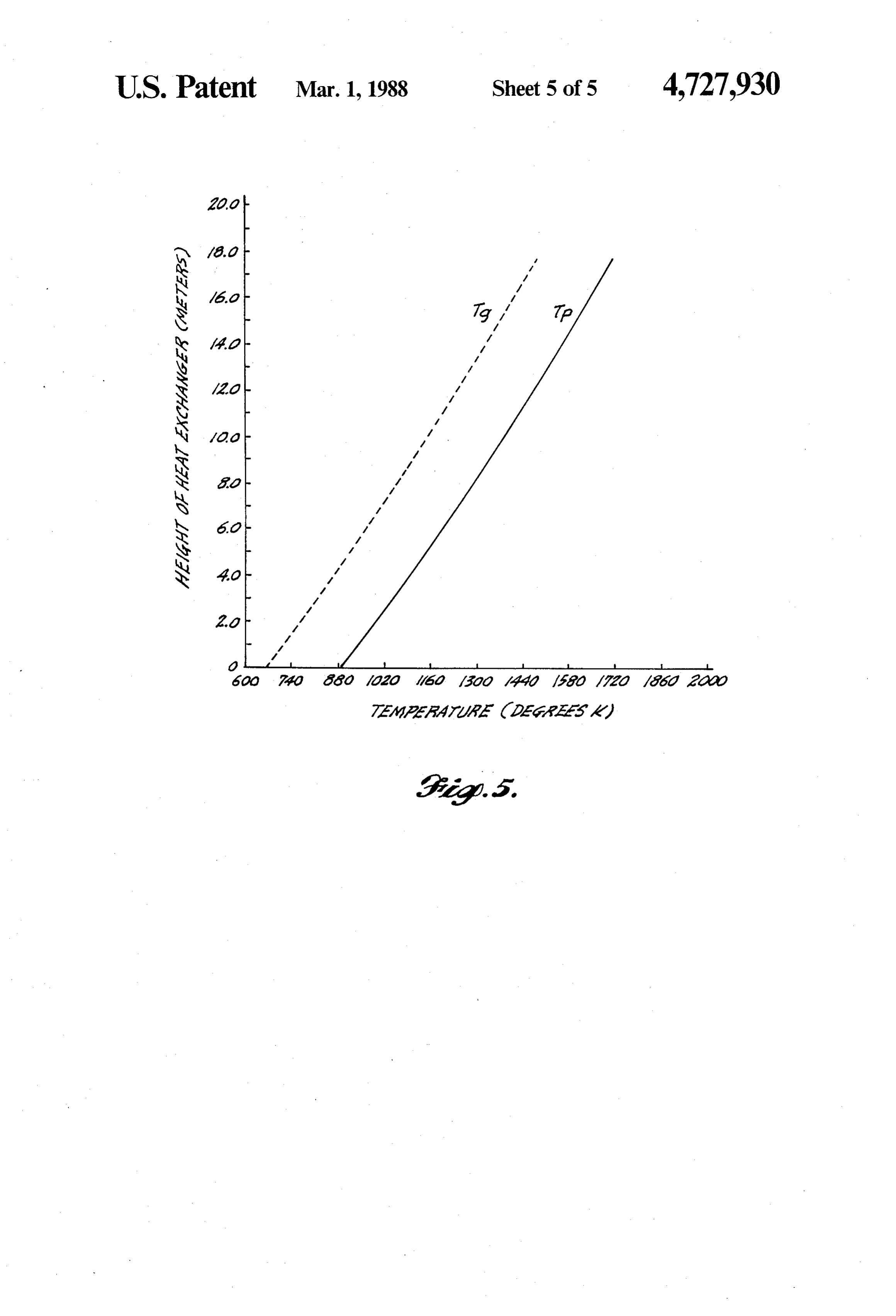
past each other between their respective inlet and outlet FIG. 5 is a graph of the height versus temperature of 63S. droplets (T) and gas (Tg) in the droplet heat exchanger. The heat exchange system provided by the present invention can be employed in an energy storage and DETAILED DESCRIPTION OF THE conversion system. Such a system comprises first a INVENTION means for heating the first heat exchange medium in an The heat exchange, energy storage and energy con elevated temperature at which it is a liquid. An engine version system of the present invention is first broadly means is provided for receiving the second heat ex described and explained in conjunction with a solid change medium at an elevated temperature and extract power system. It is to be understood, however, that a ing energy therefrom. The heat exchange means com 10 solar-powered energy conversion system is only one of prises the heat transfer chamber for transferring the many possible applications of the heat exchange and heat from the first heat exchange medium to the second energy storage system in accordance with the present heat exchange medium. The heat exchange means in invention. The energy conversion system will first be cludes means for causing the first heat exchange me broadly described followed by a more detailed explana dium to traverse the heat transfer chamber in the form 15 tion of each of its major components and subsystems. of a plurality of droplets. The heat exchange means For purposes of this explanation two heat exchange further includes means for causing the second heat ex media are employed; a first, to be referred to as the change medium to traverse the chamber in countercur "droplet medium', is chosen as a refractory oxide, such rent flow relative to the first heat exchange medium, as silica. The refractory oxide is alternately transformed thereby allowing the first and second heat exchange 20 from the solid phase to the liquid phase. The second media to make intimate thermal contact with each heat exchange medium is a relatively inert gas such as other. A means is provided for transferring the first heat argon or nitrogen.
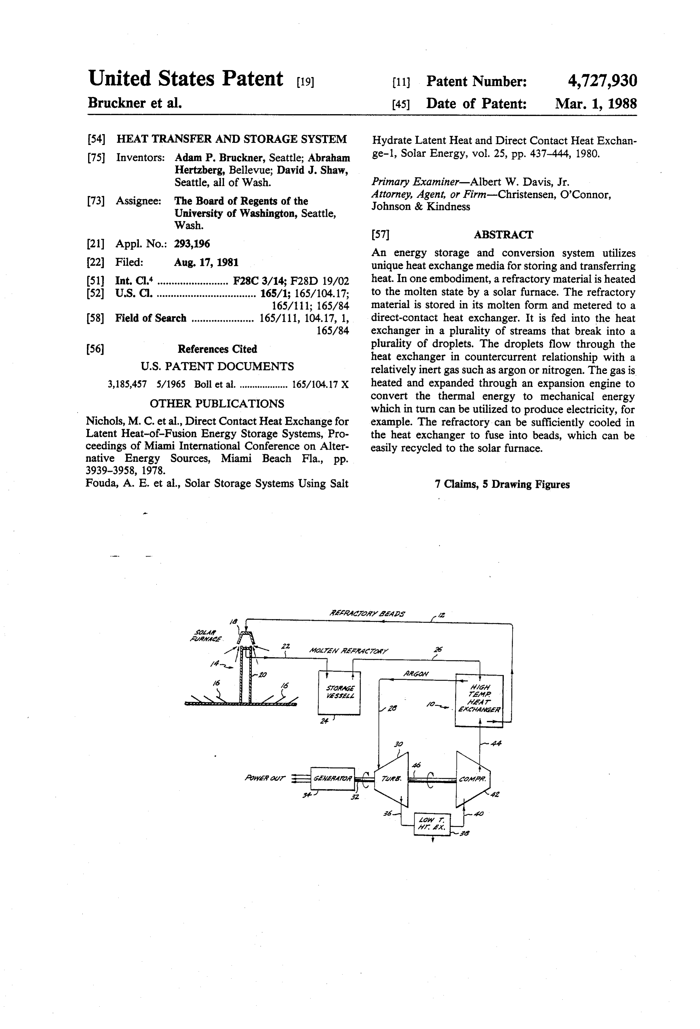
exchange medium from the means for heating to the The Energy Conversion System: heat exchange means. A means is also provided for Referring to FIG. 1, the droplet material is trans transferring the second heat exchange medium from the 25 ferred from a heat exchanger 10 in the form of refrac heat exchange means to the engine means. Importantly, tory beads along a transfer line 12 to a solar furnace a storage means for storing the first heat exchange me generally designated 14. The solar furnace 14 is situated dium at an elevated temperature can be interposed be in the middle of a heliostat field 16. A radiation receiver ...tween the means for heating the first heat exchange 18 is situated at the top of a tower 20. The heliostat field medium and the heat exchange means. In this environ 30 directs and concentrates solar energy into the radiation ment, the means for transferring the first heat exchange receiver 18. As the refractory beads pass through the . . medium includes means for transferring that medium to radiation receiver 18, the concentrated solar radiation and from the storage means. heats the refractory beads to a temperature at which In a preferred embodiment of the energy storage and they become liquid. The liquid droplet material is then conversion system, the first and second heat exchange 35 transferred by a liquid transfer line 22 to a suitable stor media respectively comprise a refractory oxide and a age vessel 24. The storage vessel is insulated to mini (relatively inert gas. An extremely inexpensive refrac mize heat loss through the walls from radiation and tory oxide, such as silica, can readily be employed with conduction. The droplet material is withdrawn from the a gaseous second heat transfer medium such as argon or storage vessel preferably at a constant rate and trans nitrogen. Silica, for example, is on an order of magni ferred through transfer line 26 to the droplet heat ex tude less expensive than conventional, competitive en changer 10, which will be described in more detail ergy storage materials. A solar furnace can be utilized below.
to melt the refractory oxide. The oxide can be stored in The droplet material is introduced into the upper end a suitable container from whence it can be continuously of the heat exchanger as a stream or plurality of streams. dispensed to a capacitive heat transfer system con 45 Each stream breaks into a plurality of droplets of sub structed in accordance with the present invention. The stantially uniform size that fall under the influence of gas is heated and can be expanded, for example, through gravity from the top toward the bottom of the heat an expansion engine to convert the heat contained in the exchanger. Simultaneously, a relatively inert, pressur gaseous second heat transfer medium to mechanical ized gas is injected into the bottom of the heat ex work. 50 changer 10 and passes upwardly in countercurrent rela BRIEF DESCRIPTION OF THE DRAWINGS tionship to the falling droplet material. As the two ma terials pass in countercurrent flow relationship, heat is
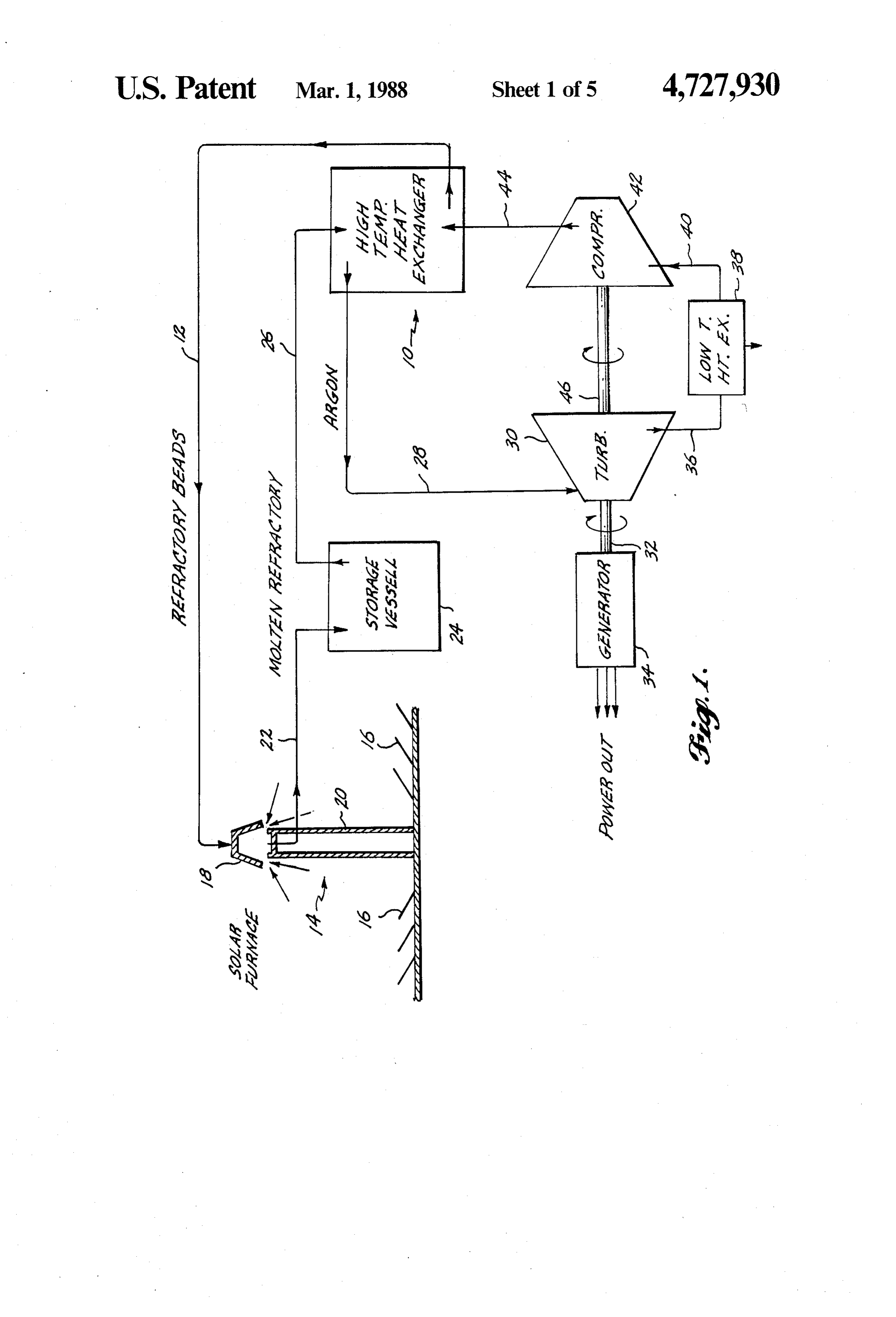
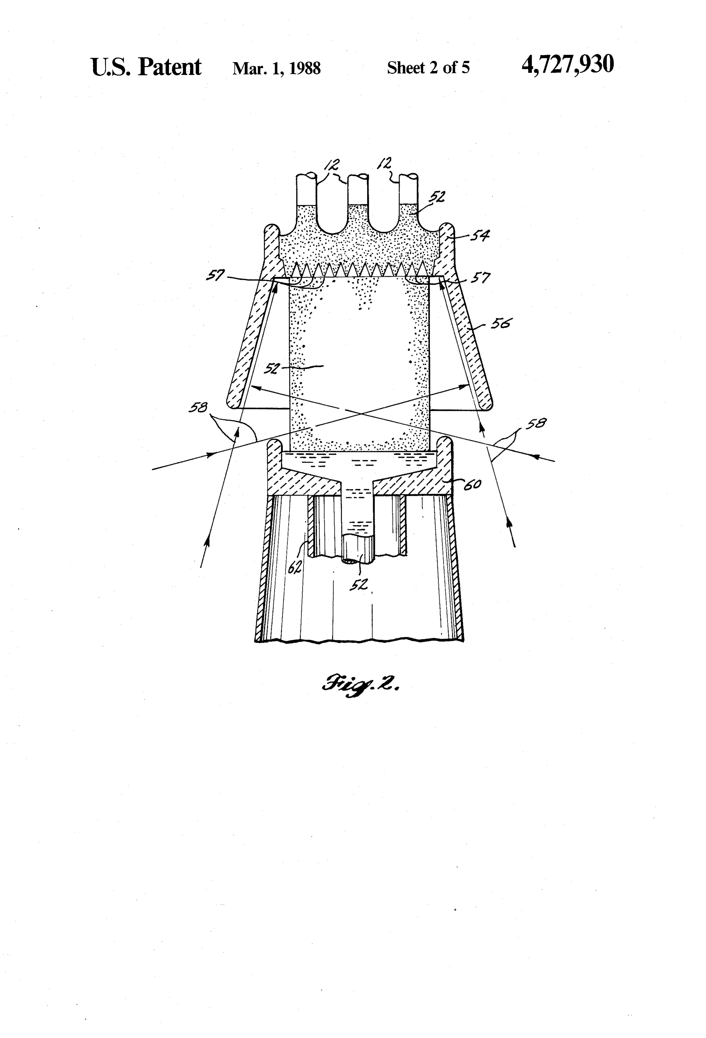
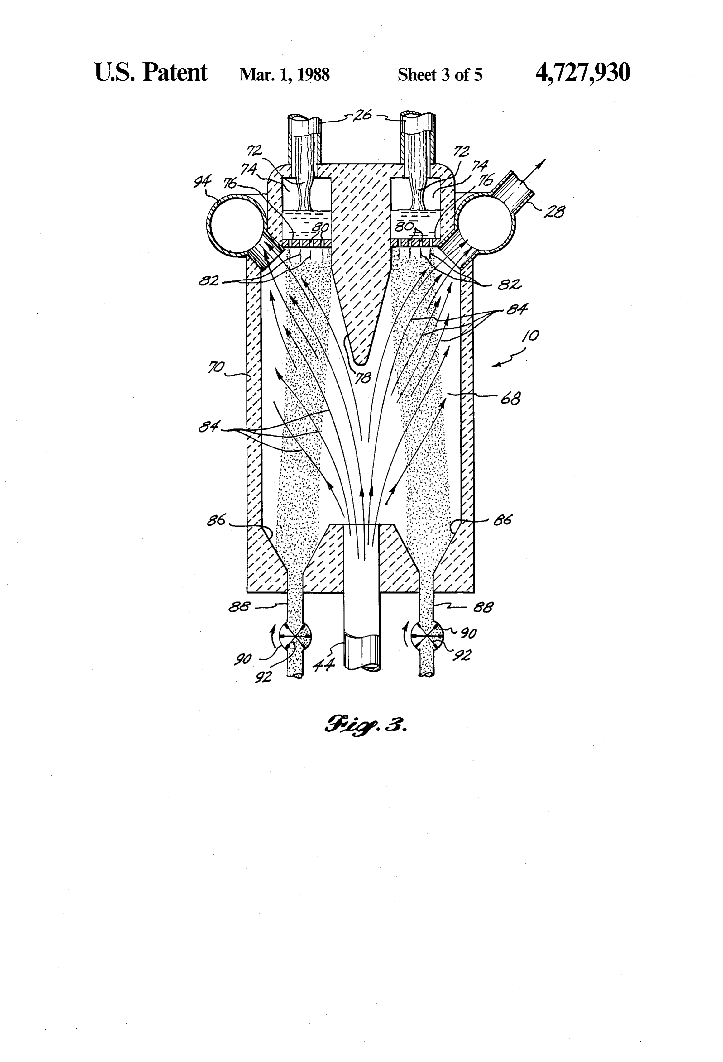
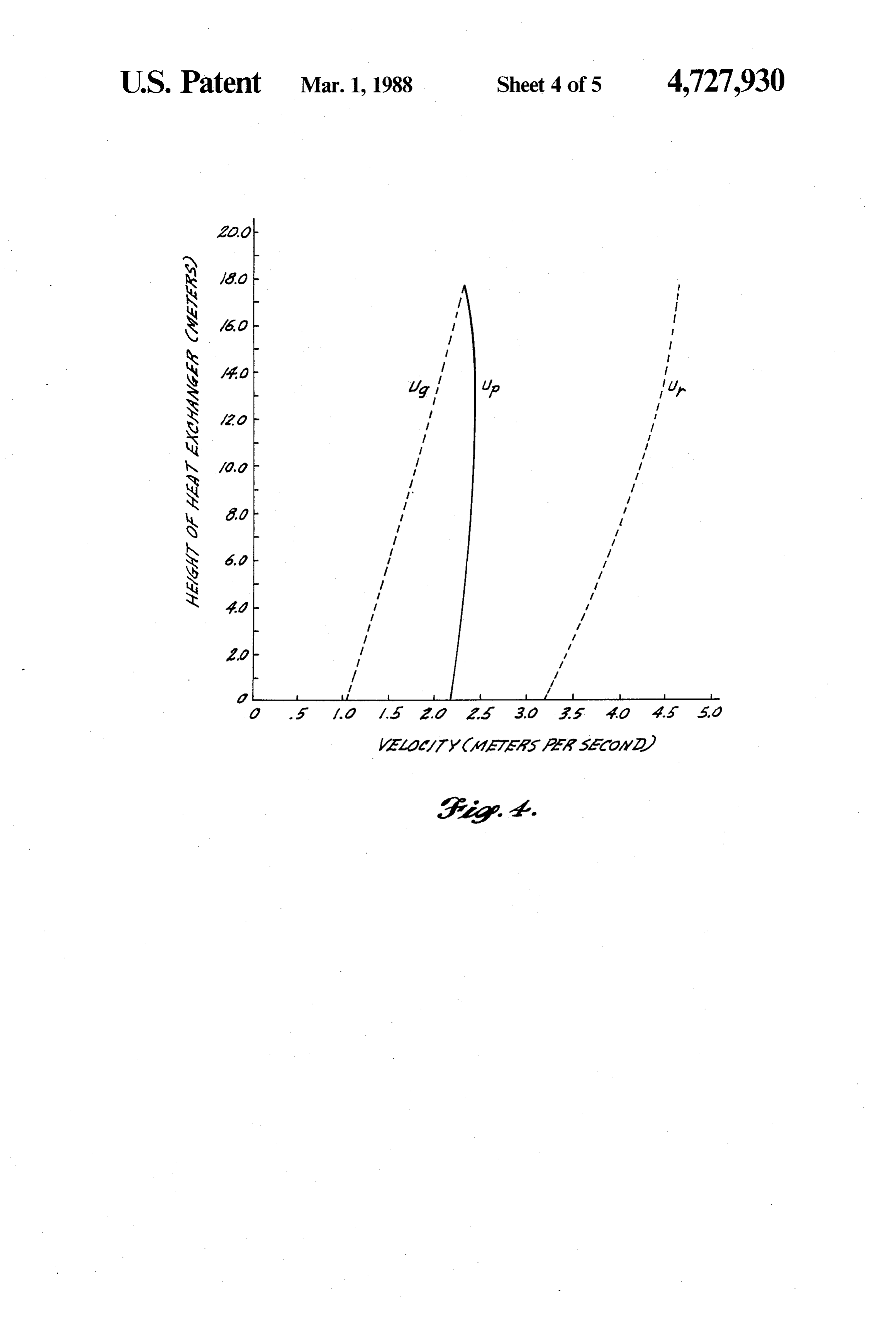
A better understanding of the present invention can exchanged from the droplet material to the gas, heating be derived by reading the ensuing specification in con the gas to a relatively high temperature. As the droplets junction with the accompanying drawings wherein: 55 fall through the heat exchanger, they give up their sen FIG. 1 is a schematic diagram of an energy conver sible heat as well as their latent heat of fusion, if any, sion system employing the heat transfer and energy and are converted from a liquid to solid refractory storage systems constructed in accordance with the beads. The refractory beads are withdrawn through a present invention; suitable valving system and returned to the solar fur FIG. 2 is a schematic diagram of a solar furnace that 60 nace 14 via the transfer line 12. can be employed to heat the first heat exchange me The gas is withdrawn adjacent the upper end of the dium; heat exchanger and transferred via a conduit 26 to an FIG. 3 is a schematic diagram of the high-tempera expansion engine 30 such as a gas turbine. The high ture, direct-contact droplet heat exchanger constructed temperature gas is expanded through the expansion in accordance with the present invention; 65 engine where it is converted to mechanical energy. The FIG. 4 is a graph of height versus velocity of droplets mechanical energy is withdrawn in this embodiment via (Up) and gas (Ug) as well as relative velocity (U) of the a rotating shaft 32, which drives an electrical generator two in the droplet heat exchanger; and 34 to produce electrical energy. The expanded gas
Page 9
leaves the turbine via outlet line 36. The gas is then line phase changes at the high working temperatures. channeled through a low-temperature heat exchanger Thus, it is possible to take advantage of higher heat 38 from which additional heat energy is extracted from capacitive effects of these materials because of the large the gas. The low-temperature gas leaves the low-tem amounts of energy that can be stored in crystalline perature heat exchanger via line 40 and is compressed 5 phase changes. Utilization of these materials could by a compressor 42 back to a pressure at which it can be therefore reduce the storage volume otherwise required injected into the droplet heat exchanger via line 44. The for pure refractory oxide.
compressor 42 is preferably driven by a second rotary The second heat exchange medium can comprise any shaft output 44 from the expansion engine 30. suitable fluid that is immiscible with the first medium A unique feature of this energy conversion system is 10 and from which heat can readily be extracted in a that thermal energy storage can be accomplished at or known energy conversion system. For the energy con near the same high thermodynamic potential at which version system disclosed, the second medium preferably the solar radiation is absorbed in the solar collector, comprises a gas that is relatively inert when compared resulting in the capability to achieve higher efficiencies with the first medium. For example, any of the inert than heretofore were practical. The high efficiency at 15 gases such as argon are satisfactory for extracting heat which the energy conversion and storage take place from a refractory oxide and then for expansion through favorably reflects back through the cost of the entire a heat engine to produce mechanical work. solar energy conversion system. For example, more The Solar Receiver:
useful energy can be obtained from a smaller heliostat Turning now to FIG. 2, the solar receiver is an im field. Additionally, the thermodynamic efficiencies of 20 portant the heat exchangers are relatively high as the droplet storage component of the solar powerplant and energy system disclosed above. The upper end of the material is always introduced into the heat exchanger at solar furnace 14 is shown in schematic longitudinal a constant high temperature, always maximizing the section. Refractory beads 52 are delivered via lines 12, thermal driving force between the heat exchange me part of the refractory bead delivery system, to a circular
trough 54 positioned above a frustoconically shaped,
The Heat Exchange Media:
Silica is only one of the materials that can be em trough 54 has diverging downwardly reradiator cavity 56. The ployed within the purview of the present invention as through which the refractoryopenings a plurality of 57 in its bottom the first heat exchange medium. The first heat exchange of particles through the reradiator cavityfall56.as Radiation
medium must have a melting point in the range desired 30 from the heliostats is beamed upwardly into the reradia for an operating and storage temperature. The medium tor cavity 56 as indicated by the arrows 58. As the must also be inert at high temperature with respect to refractory beads pass downwardly through the reradia the second heat exchange medium. The first medium tor cavity, the beads absorb solar radiation and are most preferably has a low vapor pressure to avoid con heated to or above their fusion temperature. The molten tamination of the second heat exchange medium. Re beads, or
droplet material, fall into a crucible 60 posi fractory oxides generally meet the foregoing criteria.
Refractory oxides such as alumina, lime, chromic oxide, tioned below the rearadiator cavity. A ceramic conduit magnesia, silica, soda, lithia, zirconia and mixtures 62 surrounds a flow aperture 64 in the bottom of the thereof can be employed. Silica, however, has a number crucible 60. The droplet material 52 issues from the of attractive properties, including a relatively low melt aperture 64 and falls into a storage container, preferably ing point (on the order of 1713. C.), is abundant and located below the crucible at the bottom of the solar therefore inexpensive, and is also environmentally be furnace tower. A suitably insulated ceramic pipe has a diameter on the order of three to four times that of the nign.
Although silica is relatively viscousin its molten tate, aperture 64 from the crucible 60. The droplet material the addition of metal oxides such as sodium oxide 45 flows as a free viscous jet from the aperture and does (soda), potassium oxide, lithium oxide (lithia), magne not contact the ceramic pipe as it travels downwardly sium oxide (magnesia), calcium oxide, and lead oxide from the crucible.
will reduce the viscosity of a silica melt by breaking the The reradiator cavity can be lined with oxidation continuity of the silicate cross-linking and thus render resistant carbon-composite blocks and insulated by the molten silica more susceptible to the desirable flow 50 alumina-silica fiber blankets. This structure is sur characteristics. For example, at 1725 K., the viscosity rounded by a steel shell. The structure is similar in of pure silica is approximately 100 poise. The addition construction to that described below in conjunction of 35% by weight sodium oxide reduces this viscosity to with the storage vessel. Similarly, the ceramic pipe 22 poise. Similarly, the addition of 25.0% by weight surrounding the outlet jet of droplet material is similarly lithium oxide to pure silica reduces the viscosity even 55 designed and insulated. The crucible itself is con further to 4.8 poise. Although this additional reduction structed of the same materials as the interior lining of in viscosity produced by the addition of lithium oxide is the energy storage vessel.
potentially of great benefit, lithium oxide may raise The flow of beads from the trough 54 is controlled to problems with respect to chemical attack on a storage maintain the droplet material and refractory crucible at vessel lining. Therefore, silica doping with sodium its proper maximum operating temperature. If loss of oxide is a presently preferred material. insolation occurs because of a sudden overcast or night The refractory oxides discussed above are not exclu fall, the flow of beads from the trough into the rearadia sive of the possibilities available for capacitive storage tor cavity is stopped. The remaining molten material in materials. Under the constraints that the material should the crucible is then emptied into a storage vessel. Upon be available, cheap, and benign, there are numerous 65 restarting the solar furnace, the receiver crucible is first other candidates that can be employed. For example, partially filled with refractory beads. These beads are glasses containing various mixtures of the alkaline ox then melted by reradiation from the upper section of the ides of sodium, lithium, and potassium, undergo crystal cavity. Once this initial charge is melted, the injection
Page 10
of beads from the trough through the reradiator cavity resistance to heat flow equal to the wall construction is resumed, allowing normal operation to proceed. just described. A vessel constructed as outlined above The Energy Storage System: having a diameter of about 24 meters and a height of A unique feature of the integrated energy conversion about 24 meters will suffer less than 0.85% of capacity system of the present invention is the capability of stor heat loss in or over a period of 48 hours. Of course, a ing energy at the same high thermodynamic potential at higher level of insulation in the storage vessel could which it is collected in the solar furnace. By absorbing prove to be more economical, depending on the cost of energy directly into the refractory material, energy the additional insulation relative to the thermal energy storage can very easily be integrated with the power lost. The vessel just described is suitable for storage of cycle. As briefly mentioned above, energy storage is 10 a molten refractory such as silica. Other refractory accomplished in accordance with the present invention materials having higher fusion temperatures than silica by placing the molten refractory material into a large will, of course, require different materials to directly storage vessel situated below the solar receiver. In this contact the molten material as well as may require addi manner, a reserve of high-temperature molten refrac tional insulation because of the higher driving forces tory material is available at all times, thus allowing the 15 present.
energy conversion system to operate continuously at Heat lost by conduction through the walls of the constant temperatures and outputs despite the fluctua vessel will be easily dissipated by convection to the tion in insolation or other primary source. surrounding atmosphere. It is recommended that the It is preferred that the energy storage vessel be lo tank not be located below ground level because the cated at ground level directly beneath the reradiator 20 earth, while allowing a somewhat simpler supporting cavity. The vessel is a relatively large, unpressurized structure, has an insulation value that would allow heat container that is lined and insulated. The vessel can be to accumulate in the vessel lining until the temperature sized to hold sufficient material to supply thermal en limits of the lining materials are exceeded. Thus, an ergy to the powerplant for any period it is wished to underground storage vessel would require an active accommodate. In the solar energy conversion system 25 cooling system as opposed to the passive system sug described, the minimum size vessel would be that re gested for an aboveground vessel.
quired to hold a sufficient amount of molten refractory The Direct-Contact Heat Exchanger: material to run the energy output device during the The direct-contact heat exchanger is an important night hours. Preferably, of course, the system would and integral part of the energy conversion system just - store more material than this, as there may be times 30 described. It, however, by itself, constitutes a separate . . when the sun may be blocked for spans greater than a invention that is usable not only in the environment of . nocturnal period because of atmospheric conditions. the energy conversion system herein described, but in The storage container is constructed with due regard many other applications as well. Referring to FIG. 3, for the physical and chemical stability of the first heat the direct-contact heat exchanger 10 comprises a single exchange medium, for example, the molten refractory 35large pressure vessel 70 that houses a heat transfer material. For the latter material, much information rele chamber 68. The vessel 70 is insulated from the inside in vant to the design and construction of such containers is a manner similar to that of the storage vessel. The use of ... available from the highly developed technology of the carbon as a liner material is preferred because it is not glass industry. For example, the vessel walls can be wetted by the molten refractory material. Molten re constructed of a plurality of layers of heat-resistant and fractory 72 enters an annular channel 74 at the top of insulating materials. The interior hot face of the vessel the vessel 70 through the line 26. An annular plate 76 which is in direct contact with the molten storage mate forms the bottom of the annular channel 74 and sur rial can be composed of fused-cast alumina-zirconia or rounds a flow divider 78 that extends and diverges carbon blocks in a layer about 30 centimeters thick. The downwardly into the chamber 68. The plate 76 com same material is utilized in sidewalls of glass-melting 45 prises a material that can withstand the heat of the mol furnaces and is resistant both to the high temperature ten refractory such as an alumina-zirconia or carbon and chemical attack of molten storage materials such as material. The plate 76 carries a plurality of orifices 80 silica. The alumina-zirconia blocks are very dense and through which the molten refractory is issued at the top are manufactured to close dimensional tolerances, effec of the chamber 68 in a plurality of streams 82. The tively eliminating surface porosity in the joints that 50 molten refractory is forced through the orifices 80 by a otherwise make common refractory material subject to pressurized gas in the annular channel 74 to drive the corrosion by liquid glass or silica. Additionally, a lining refractory through the nozzles and out in the streams constructed of assembled blocks is more easily repaired 82. Each of these streams 82 is relatively small in diame than a monolithic structure. Additionally, these con ter and is externally excited so that it breaks up quickly struction materials are initially relatively inexpensive 55 into a series of uniform drops that fall together, in a and are inexpensive to maintain. shower through the heat exchanger, transferring their Positioned radially outwardly from and adjoining the stored heat to a working gas or other suitable fluid. alumina-zirconia blocks is a 23-cm thick layer of light weight insulating silica-alumina refractory with a tem provided by subjectingofthethestream External excitation refractory stream can be to a mechanical vi perature rating of about 1900 K. Sandwiched outside bration. The frequency of the vibration
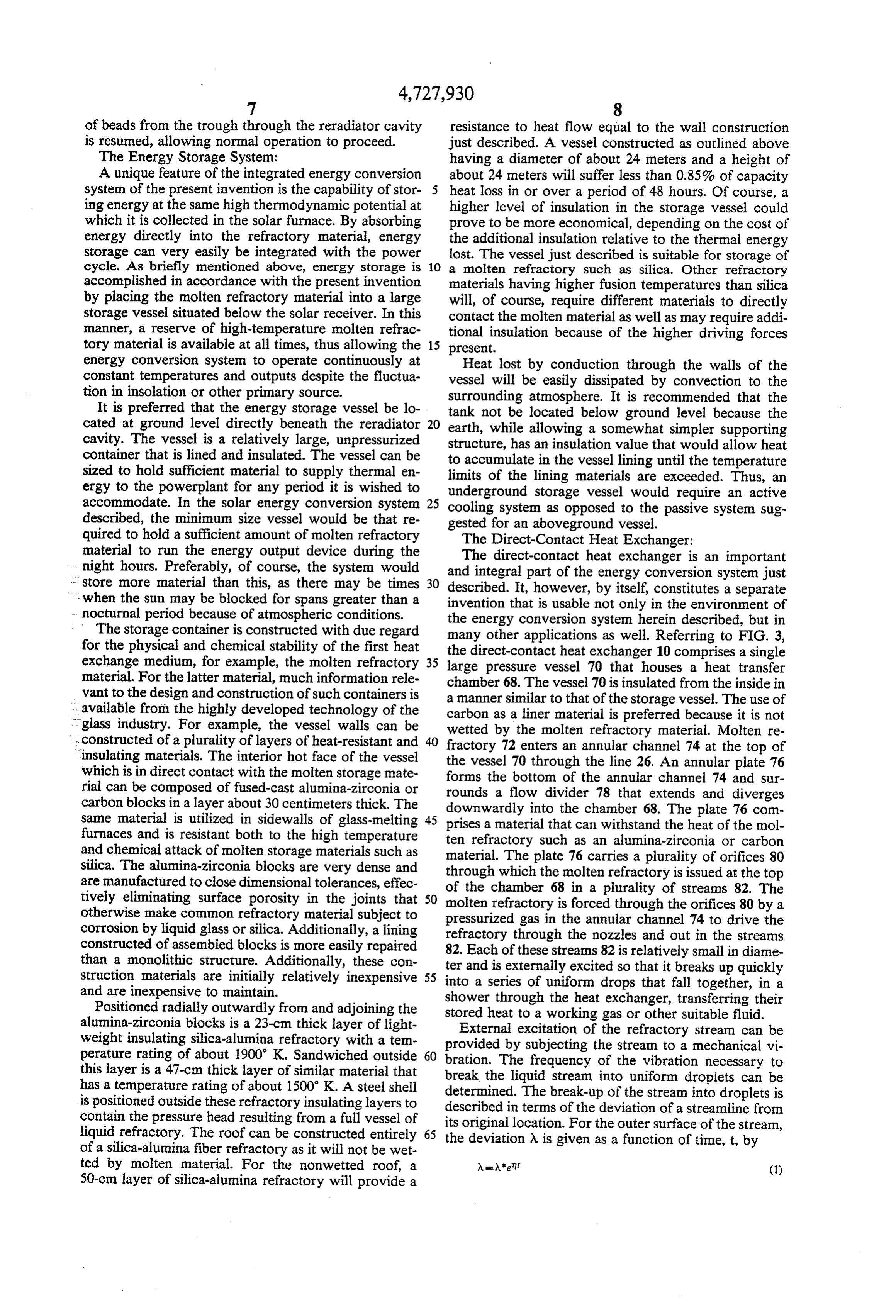
this layer is a 47-cm thick layer of similar material that break the liquid stream into uniform droplets can be has a temperature rating of about 1500 K. A steel shell determined. The break-up of the stream into droplets is positioned outside these refractory insulating layers to described in terms of the deviation of a streamline fromis contain the pressure head resulting from a full vessel of its original location. For the outer surface of the stream, liquid refractory. The roof can be constructed entirely 65 the deviation A is given as a function of time, t, by of a silica-alumina fiber refractory as it will not be wet ted by molten material. For the nonwetted roof, a 50-cm layer of silica-alumina refractory will provide a
Page 11
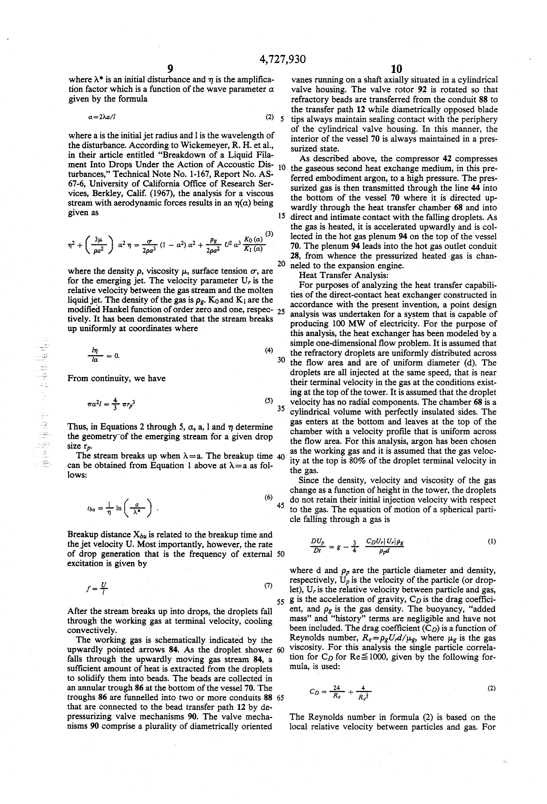
where A* is an initial disturbance and m is the amplifica vanes running on a shaft axially situated in a cylindrical tion factor which is a function of the wave parameter a valve housing. The valve rotor 92 is rotated so that given by the formula refractory beads are transferred from the conduit 88 to the transfer path 12 while diametrically opposed blade as a 2Aal (2) 5 tips always maintain sealing contact with the periphery of the cylindrical valve housing. In this manner, the where a is the initial jet radius and l is the wavelength of interior of the vessel 70 is always maintained in a pres the disturbance. According to Wickemeyer, R. H. et al., surized state.
in their article entitled "Breakdown of a Liquid Fila As described above, the compressor 42 compresses ment Into Drops Under the Action of Accoustic Dis O the gaseous second heat exchange medium, in this pre turbances,” Technical Note No. 1-167, Report No. AS ferred embodiment argon, to a high pressure. The pres 67-6, University of California Office of Research Ser vices, Berkley, Calif. (1967), the analysis for a viscous surized the gas is then transmitted through the line 44 into bottom of the vessel 70 where it is directed up stream with aerodynamic forces results in an m(a) being wardly through the heat transfer chamber 68 and into 15 direct and intimate contact with the falling droplets. As
the gas is heated, it is accelerated upwardly and is col or K0 (a) (3) lected in the hot gas plenum 94 on the top of the vessel 2pa (1 - a) a + U2 a. K (c) 70. The plenum 94 leads into the hot gas outlet conduit
28, from whence the pressurized heated gas is chan where the density p, viscosity u, surface tension o, are neled to the expansion engine. for the emerging jet. The velocity parameter U is the Heat Transfer Analysis:
relative velocity between the gas stream and the molten For purposes of analyzing the heat transfer capabili ties liquid jet. The density of the gas is pg. Ko and K1 are the accordance of the direct-contact heat exchanger constructed in modified Hankel function of order zero and one, respec 25 analysis waswith the present invention, a point design undertaken for a system that is capable of tively. It has been demonstrated that the stream breaks producing 100 MW of electricity. For the purpose of up uniformly at coordinates where this analysis, the heat exchanger has been modeled by a simple one-dimensional flow problem. It is assumed that -- = 0. (4)4. 30 the refractory droplets are uniformly distributed across the flow area and are of uniform diameter (d). The
From continuity, we have droplets are all injected at the same speed, that is near their terminal velocity in the gas at the conditions exist ing at the top of the tower. It is assumed that the droplet
Trail = arr (5) 35 velocity has no radial components. The chamber 68 is a cylindrical volume with perfectly insulated sides. The
Thus, in Equations 2 through 5, a, a, l and m determine chamber gas enters at the bottom and leaves at the top of the the geometry of the emerging stream for a given drop the flow area. with a velocity profile that is uniform across size rp. For this analysis, argon has been chosen The stream breaks up when A=a. The breakup time ity at the top is gas as the working
and it is assumed that the gas veloc of the droplet terminal velocity in can be obtained from Equation 1 above at A=a as fol the gas.
lows:
Since the density, velocity and viscosity of the gas change as a function of height in the tower, the droplets (6) do not retain their initial injection velocity with respect
ibu = . In ( ;-) to the gas. The equation of motion of a spherical parti cle falling through a gas is
Breakup distance Xbu is related to the breakup time and DU CDU, Upg the jet velocity U. Most importantly, however, the rate of drop generation that is the frequency of external 50
excitation is given by where d and p are the particle diameter and density, respectively, Up is the velocity of the particle (or drop f= U.l (7) let), U, is the relative velocity between particle and gas, 55 g is the acceleration of gravity, CD is the drag coeffici
After the stream breaks up into drops, the droplets fall ent, and pg is the gas density. The buoyancy, "added through the working gas at terminal velocity, cooling mass' and "history' terms are negligible and have not convectively. been included. The drag coefficient (CD) is a function of The working gas is schematically indicated by the Reynolds number, Re=pgUd/ug, where ug is the gas upwardly pointed arrows 84. As the droplet, shower 60 viscosity. For this analysis the single particle correla falls through the upwardly moving gas stream 84, a tion for CD for Res 1000, given by the following for sufficient amount of heat is extracted from the droplets mula, is used:
to solidify them into beads. The beads are collected in an annular trough 86 at the bottom of the vessel 70. The (2) troughs 86 are funnelled into two or more conduits 88 65 that are connected to the bead transfer path 12 by de pressurizing valve mechanisms 90. The valve mecha The Reynolds number in formula (2) is based on the nisms 90 comprise a plurality of diametrically oriented local relative velocity between particles and gas. For
Page 12
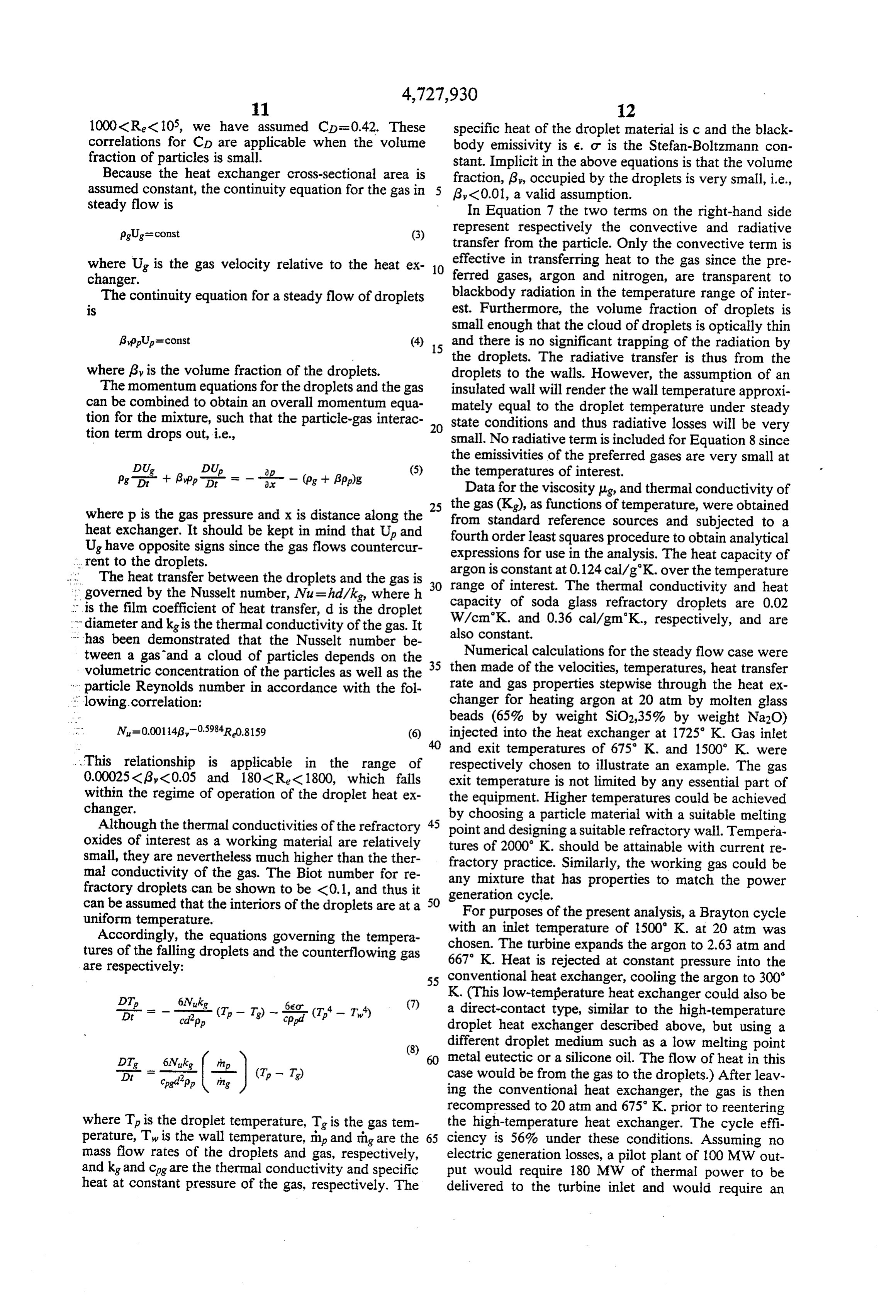
1000<Re (105, we have assumed CD=0.42. These specific heat of the droplet material is c and the black correlations for CD are applicable when the volume body emissivity is e. or is the Stefan-Boltzmann con fraction of particles is small. stant. Implicit in the above equations is that the volume Because the heat exchanger cross-sectional area is fraction, 6, occupied by the droplets is very small, i.e., assumed constant, the continuity equation for the gas in Ry C0.01, a valid assumption. steady flow is In Equation 7 the two terms on the right-hand side pg.Ug=const (3) represent respectively the convective and radiative transfer from the particle. Only the convective term is where U is the gas velocity relative to the heat ex 10 ferredeffective in transferring heat to the gas since the pre changer. gases, argon and nitrogen, are transparent to The continuity equation for a steady flow of droplets blackbody radiation in the temperature range of inter is est. Furthermore, the volume fraction of droplets is small enough that the cloud of droplets is optically thin
Appup=const (4) 15 and there is no significant trapping of the radiation by the droplets. The radiative transfer is thus from the where 6 is the volume fraction of the droplets. droplets to the walls. However, the assumption of an The momentum equations for the droplets and the gas insulated wall will render the wall temperature approxi can be combined to obtain an overall momentum equa mately equal to the droplet temperature under steady tion for the mixture, such that the particle-gas interac 20 state conditions and thus radiative losses will be very tion term drops out, i.e., small. No radiative term is included for Equation 8 since the emissivities of the preferred gases are very small at
= - - - - (p + Appg (5) the temperatures of interest.
Data for the viscosity pig and thermal conductivity of where p is the gas pressure and x is distance along the fromgasstandard the 25 (K), as functions of temperature, were obtained heat exchanger. It should be kept in mind that Up and fourth order leastreference squares sources and subjected to a procedure to obtain analytical
U have opposite signs since the gas flows countercur expressions for use in the analysis. The heat capacity of ... rent to the droplets.
... The heat transfer between the droplets and the gas is 30 argon is constant at 0.124 cal/g'K. over the temperature range of interest. The thermal conductivity and heat governed by the Nusselt number, Nu=hd/kg, where h capacity is the film coefficient of heat transfer, d is the droplet W/cmK.ofandsoda 0.36 glass refractory droplets are 0.02 cal/gm.K., respectively, and are diameter and kg is the thermal conductivity of the gas. It also constant.
has been demonstrated that the Nusselt number be tween a gas and a cloud of particles depends on the 35 Numerical calculations for the steady flow case were volumetric concentration of the particles as well as the then made of the velocities, temperatures, heat transfer particle Reynolds number in accordance with the fol rate and gas properties stepwise through the heat ex lowing.correlation: changer for heating argon at 20 atm by molten glass beads (65% by weight SiO2,35% by weight Na2O)
N=0.001143,0598R0.8159 (6) injected into the heat exchanger at 1725 K. Gas inlet 40 and exit temperatures of 675 K. and 1500 K. were
This relationship is applicable in the range of respectively chosen to illustrate an example. The gas 0.00025((3 (0.05 and 180CR <1800, which falls exit temperature is not limited by any essential part of within the regime of operation of the droplet heat ex the equipment. Higher temperatures could be achieved changer. by choosing a particle material with a suitable melting Although the thermal conductivities of the refractory 45 point and designing a suitable refractory wall. Tempera oxides of interest as a working material are relatively tures of 2000 K. should be attainable with current re small, they are nevertheless much higher than the ther fractory practice. Similarly, the working gas could be mal conductivity of the gas. The Biot number for re any mixture that has properties to match the power fractory droplets can be shown to be <0.1, and thus it generation cycle.
can be assumed that the interiors of the droplets are at a 50 For purposes of the present analysis, a Brayton cycle uniform temperature.
Accordingly, the equations governing the tempera with an The inlet temperature of 1500 K. at 20 atm was tures of the falling droplets and the counterflowing gas chosen.
turbine expands the argon to 2.63 atm and is rejected at constant pressure into the are respectively:
55 conventional heat exchanger, cooling the argon to 300
K. (This low-temperature heat exchanger could also be a direct-contact type, similar to the high-temperature -of----- (T. - T - T - T.) droplet heat exchanger described above, but using a (8) different droplet medium such as a low melting point
DT 6Nuk metal eutectic or a silicone oil. The flow of heat in this . . = cpgdipp- - ingin - | (T-T) case would be from the gas to the droplets.) After leav ing the conventional heat exchanger, the gas is then recompressed to 20 atm and 675 K. prior to reentering where T is the droplet temperature, T is the gas tem the high-temperature heat exchanger. The cycle effi perature, Twis the wall temperature, in and rhg are the 65 ciency is 56% under these conditions. Assuming no mass flow rates of the droplets and gas, respectively, electric generation losses, a pilot plant of 100 MW out and kg and cog are the thermal conductivity and specific put would require 180 MW of thermal power to be heat at constant pressure of the gas, respectively. The delivered to the turbine inlet and would require an
Page 13
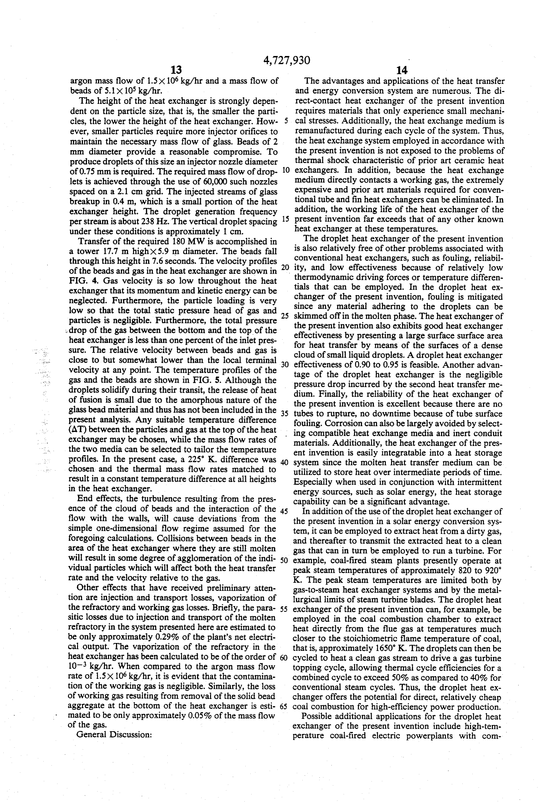
argon mass flow of 1.5x 10⁶ kg/hr and a mass flow of The advantages and applications of the heat transfer beads of 5.1 x 10⁵ kg/hr. and energy conversion system are numerous. The di The height of the heat exchanger is strongly depen rect-contact heat exchanger of the present invention dent on the particle size, that is, the smaller the parti requires materials that only experience small mechani cles, the lower the height of the heat exchanger. How 5 cal stresses. Additionally, the heat exchange medium is ever, smaller particles require more injector orifices to remanufactured during each cycle of the system. Thus, maintain the necessary mass flow of glass. Beads of 2 the heat exchange system employed in accordance with mm diameter provide a reasonable compromise. To the present invention is not exposed to the problems of produce droplets of this size an injector nozzle diameter thermal shock characteristic of prior art ceramic heat of 0.75 mm is required. The required mass flow of drop 10 exchangers. In addition, because the heat exchange lets is achieved through the use of 60,000 such nozzles medium directly contacts a working gas, the extremely spaced on a 2.1 cm grid. The injected streams of glass expensive and prior art materials required for conven breakup in 0.4m, which is a small portion of the heat tional tube and fin heat exchangers can be eliminated. In exchanger height. The droplet generation frequency addition, the working life of the heat exchanger of the per stream is about 238 Hz. The vertical droplet spacing 15 present invention far exceeds that of any other known heat exchanger at these temperatures.
under these conditions is approximately 1 cm.
Transfer of the required 180 MW is accomplished in The droplet heat exchanger of the present invention a tower 17.7 m highx5.9 m diameter. The beads fall isconventional also relatively free of other problems associated with heat exchangers, such as fouling, reliabil through this height in 7.6 seconds. The velocity profiles ity, and low effectiveness because of relatively low of the beads and gas in the heat exchanger are shown in 20 thermodynamic
FIG. 4. Gas velocity is so low throughout the heat tials that can bedriving forces or temperature differen employed. In the droplet heat ex exchanger that its momentum and kinetic energy can be changer of the present invention, fouling is mitigated neglected. Furthermore, the particle loading is very since any material adhering to the droplets can be low so that the total static pressure head of gas and particles is negligible. Furthermore, the total pressure 25 skimmed offin the molten phase. The heat exchanger of the present invention also exhibits good heat exchanger drop of the gas between the bottom and the top of the effectiveness by presenting a large surface surface area heat exchanger is less than one percent of the inlet pres for heat transfer by means of the surfaces of a dense sure. The relative velocity between beads and gas is close to but somewhat lower than the local terminal 30 cloud of small liquid droplets. A droplet heat exchanger effectiveness of 0.90 to 0.95 is feasible. Another advan velocity at any point. The temperature profiles of the tage of the droplet heat exchanger is the negligible gas and the beads are shown in FIG. 5. Although the pressure drop incurred by the second heat transfer me droplets solidify during their transit, the release of heat dium. Finally, the reliability of the heat exchanger of of fusion is small due to the amorphous nature of the the present invention is excellent because there are no glass bead material and thus has not been included in the 35 tubes to rupture, no downtime because of tube surface present analysis. Any suitable temperature difference fouling. Corrosion can also be largely avoided by select (AT) between the particles and gas at the top of the heat exchanger may be chosen, while the mass flow rates of ing compatible heat exchange media and inert conduit materials. Additionally, the heat exchanger of the pres the two media can be selected to tailor the temperature ent invention is easily integratable into a heat storage profiles. In the present case, a 225 K. difference was 40 system since the molten heat transfer medium can be chosen and the thermal mass flow rates matched to result in a constant temperature difference at all heights utilized to store heat over intermediate periods of time. Especially when used in conjunction with intermittent in the heat exchanger. energy sources, such as solar energy, the heat storage End effects, the turbulence resulting from the pres capability can be a significant advantage. ence of the cloud of beads and the interaction of the 45 In addition of the use of the droplet heat exchanger of flow with the walls, will cause deviations from the the present invention in a solar energy conversion sys simple one-dimensional flow regime assumed for the tem, it can be employed to extract heat from a dirty gas, foregoing calculations. Collisions between beads in the area of the heat exchanger where they are still molten and thereafter to transmit the extracted heat to a clean gas that can in turn be employed to run a turbine. For will result in some degree of agglomeration of the indi 50 example, coal-fired steam plants presently operate at vidual particles which will affect both the heat transfer peak steam temperatures of approximately 820 to 920 rate and the velocity relative to the gas. K. The peak steam temperatures are limited both by Other effects that have received preliminary atten gas-to-steam heat exchanger systems and by the metal tion are injection and transport losses, vaporization of lurgical limits of steam turbine blades. The droplet heat the refractory and working gas losses. Briefly, the para 55 exchanger of the present invention can, for example, be sitic losses due to injection and transport of the molten employed in the coal combustion chamber to extract refractory in the system presented here are estimated to heat directly from the flue gas at temperatures much be only approximately 0.29% of the plant's net electri closer to the stoichiometric flame temperature of coal, cal output. The vaporization of the refractory in the that is, approximately 1650 K. The droplets can then be heat exchanger has been calculated to be of the order of 60 cycled to heat a clean gas stream to drive a gas turbine 103 kg/hr. When compared to the argon mass flow topping cycle, allowing thermal cycle efficiencies for a rate of 1.5x 10⁶ kg/hr, it is evident that the contamina combined cycle to exceed 50% as compared to 40% for tion of the working gas is negligible. Similarly, the loss conventional steam cycles. Thus, the droplet heat ex of working gas resulting from removal of the solid bead changer offers the potential for direct, relatively cheap aggregate at the bottom of the heat exchanger is esti 65 coal combustion for high-efficiency power production. mated to be only approximately 0.05% of the mass flow Possible additional applications for the droplet heat of the gas. exchanger of the present invention include high-tem General Discussion: perature coal-fired electric powerplants with com
Page 14
pressed air storage and thermal energy storage, air hydrogen to temperatures that heretofore could be blown, coal gasification plants, hydrogen heaters, solar reached only by side reactions (i.e., combustion) that thermal powerplants, low-temperature applications tended to contaminate the product output. such as geothermal power applications, and thermal The solar thermal powerplant generally described powerplant dry cooling towers. In these other applica can capitalize on both the high temperature heat trans tions the heat transfer media employed in the direct fer capabilities of the droplet heat exchanger and the contact heat exchanger are certainly not limited to a thermal storage features of the heat transfer medium. refractory oxide and an inert gas. For example, liquid By storing the heat in a molten glass, storage costs may metals, in pure, alloy or eutectic form can be employed be reduced by an order of magnitude over the nearest as the first heat exchange media in lower temperature 10 competitor (e.g., molten salts). The increase in effi applications. These media can be employed with rela ciency of the accompanying power cycle associated tively inert gaseous second media such as steam, even with the peak temperature capabilities of the droplet with liquids such as hot water. The basic criteria of the heat exchanger also helps to reduce the size and cost of two media set forth in connection with the refractory all upstream components (i.e., heliostat field, solar oxides above must still however be carefully observed. 15
An especially important criterion is that the media must reciver,
The and thermal storage unit).
present invention has been described in conjunc be immiscible as well as substantially insoluble in each tion with a preferred embodiment of the direct-contact other, that is, having a mutually insolubility of on the heat exchanger and energy storage system as well as the order of less than 0.001%.
A coal-fired electric power plant can use the droplet 20 advantages may be derivedsystem.
overall energy conversion Further details and by reading the related arti heat exchanger as a means of storing high-temperature cles by Shaw, David J. et al., “A New Method of Effi heat at the same time that compressed air is stored in an underground cavern. The coal combustion system cient Heat Transfer and Storage at Very High Temper atures,' 15th Intersociety Energy Conversion Engi transfers heat during off-peak hours to one of the tur neering Conference, Seattle, Wash., Aug. 18-22, 1980; bine stages to drive the air compressor and charge the 25 and Bruckner, Adam P. et al., "A New Method for caverns. Part of the heat transfer medium from the droplet heat exchanger is also deposited in the thermal High Temperature Solar Thermal Energy Conversion storage unit. When air is withdrawn from the com and Storage", Solar Thermal Test Facilities Users' As pressed air storage it is reheated by the stored thermal sociation
Annual Meeting, Pasedena, Calif., Apr. 21-24, both of which are expressly incorporated herein storage unit. When air is withdrawn from the com 30 pressed air storage is reheated by the stored thermal by reference. One of ordinary skill, after reading the energy in order to drive the peaking power turbine. foregoing specification, however, will be able to effect various changes, substitutions of equivalents, and other
Without stored thermal energy, a clean fuel such as alterations natural gas or No. 2 fuel oil must be burned for the to the disclosed embodiments without de peaking turbine. The droplet heat exchanger, therefore, 35 parting from the broad concepts embodied herein. It is has the potential for storing heat at sufficiently high therefore intended that the scope of the protection temperatures (i.e., 1500 K.) to displace scarce clean granted by Letters Patent hereon be limited only by the fuels in this peaking power application. Instead, coal definition contained in the appended claims and equiva can be burned directly with conventional low-tempera lents thereof.
ture stack gas cleanup. Furthermore, since the coal can The embodiments of the invention in which an exclu be burned over a much longer period (i.e., off-peak sive property or privilege is claimed are defined as hours) the coal combustor and stack gas cleanup system follows:
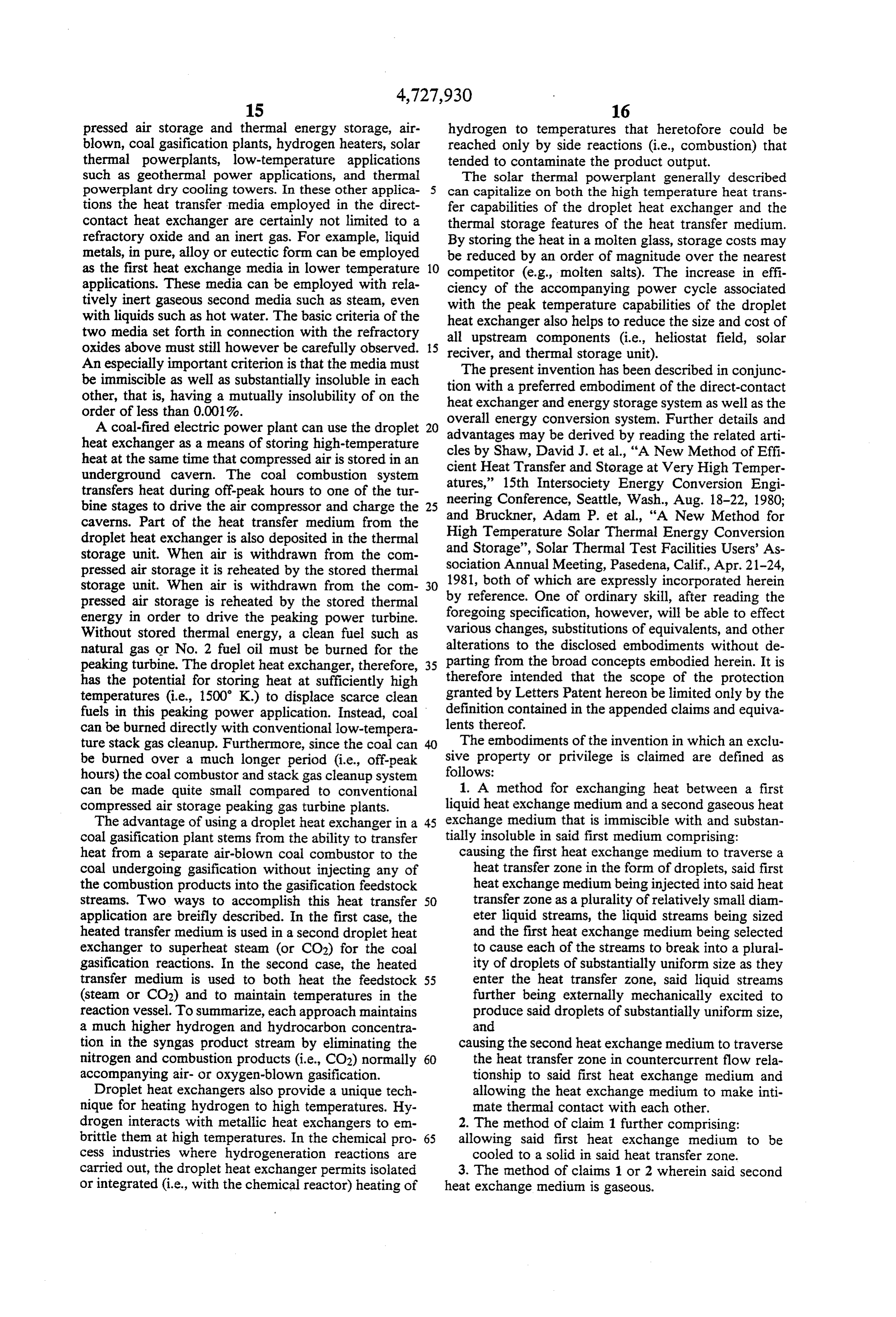
can be made quite small compared to conventional 1. A method for exchanging heat between a first compressed air storage peaking gas turbine plants. liquid heat exchange medium and a second gaseous heat The advantage of using a droplet heat exchanger in a 45 exchange medium that is immiscible with and substan coal gasification plant stems from the ability to transfer tially insoluble in said first medium comprising: heat from a separate air-blown coal combustor to the causing the first heat exchange medium to traverse a coal undergoing gasification without injecting any of heat transfer zone in the form of droplets, said first the combustion products into the gasification feedstock heat exchange medium being injected into said heat streams. Two ways to accomplish this heat transfer 50 transfer zone as a plurality of relatively small diam application are breifly described. In the first case, the eter liquid streams, the liquid streams being sized heated transfer medium is used in a second droplet heat and the first heat exchange medium being selected exchanger to superheat steam (or CO2) for the coal to cause each of the streams to break into a plural gasification reactions. In the second case, the heated ity of droplets of substantially uniform size as they transfer medium is used to both heat the feedstock 55 enter the heat transfer zone, said liquid streams (steam or CO2) and to maintain temperatures in the further being externally mechanically excited to reaction vessel. To summarize, each approach maintains produce said droplets of substantially uniform size, a much higher hydrogen and hydrocarbon concentra and tion in the syngas product stream by eliminating the causing the second heat exchange medium to traverse nitrogen and combustion products (i.e., CO2) normally 60 the heat transfer zone in countercurrent flow rela accompanying air- or oxygen-blown gasification. tionship to said first heat exchange medium and Droplet heat exchangers also provide a unique tech allowing the heat exchange medium to make inti nique for heating hydrogen to high temperatures. Hy mate thermal contact with each other. drogen interacts with metallic heat exchangers to em 2. The method of claim 1 further comprising: brittle them at high temperatures. In the chemical pro 65 allowing said first heat exchange medium to be cess industries where hydrogeneration reactions are cooled to a solid in said heat transfer zone. carried out, the droplet heat exchanger permits isolated 3. The method of claims 1 or 2 wherein said second or integrated (i.e., with the chemical reactor) heating of heat exchange medium is gaseous.
Page 15
4. The method of claim 3 wherein said first and sec alumina, lime, chronic oxide, magnesia, silica, soda, ond heat exchange media are substantially inert relative lithia, zirconia, and mixtures thereof. to each other. 7. The method of claim 1 wherein said first heat ex 5. The method of claim 3 wherein said first heat ex 5 change medium is injected into said heat transfer zone in a plurality of liquid streams sized to cause said first change medium is a refractory oxide. heat exchange medium in each of said streams to break 6. The method of claim 5 wherein said first heat ex into a plurality of droplets of substantially uniform size. change medium is selected from the group consisting of k is is
Page 16
UNITED STATES PATENT AND TRADEMARK OFFICE
CERTIFICATE OF CORRECTION
PATENT NO. : 4,727,930 Page 1 of 2
INVENTOR(S) : AClam P. Bruckner et al.
It is certified that error appears in the above-identified patent and that said Letters Patent is hereby Corrected as shown below:
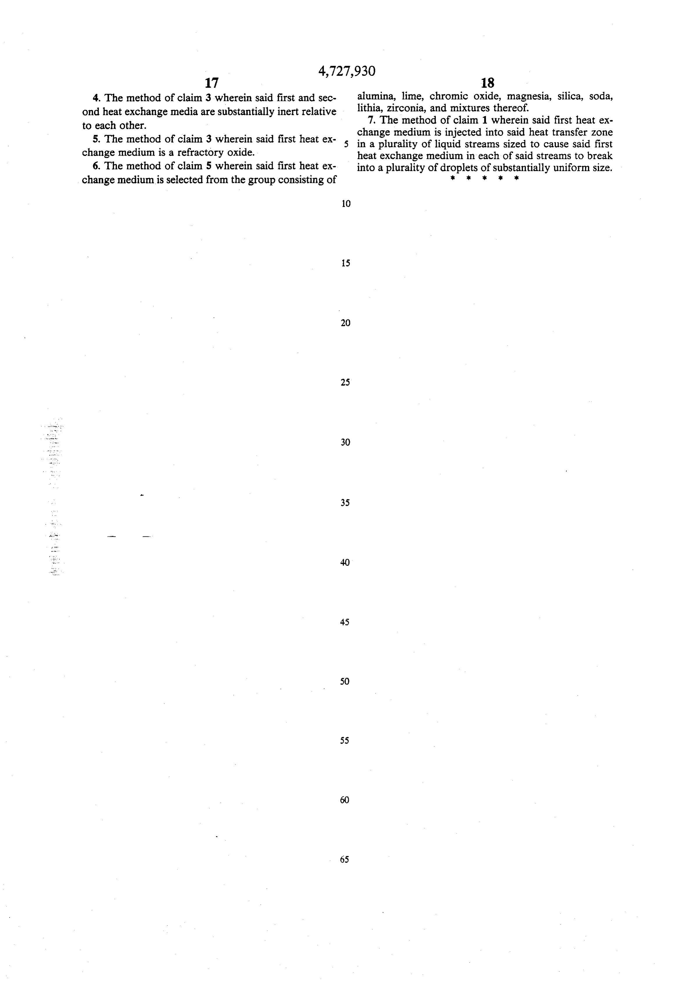
Column 1, line 44: "sytems" should be --systems-- Column 2, line 55: "th" should be --the--
Column 5, line 44: "tate" should be --State--
Column 5, line 60: "doping" should be --doped-- Column 9, line 4: "A"Should be -- T--
Column 9, line 18: "U," should be --U--
Column 9, line 50: Insert --f,-- after "generation" Column 9, line 51: Insert --, -- (comma) after "excitation" Note that the equations located at Columns 10 and 11 should be renumbered as follows:
Column 11, line 25: Insert --the-- before "distance"
Page 17
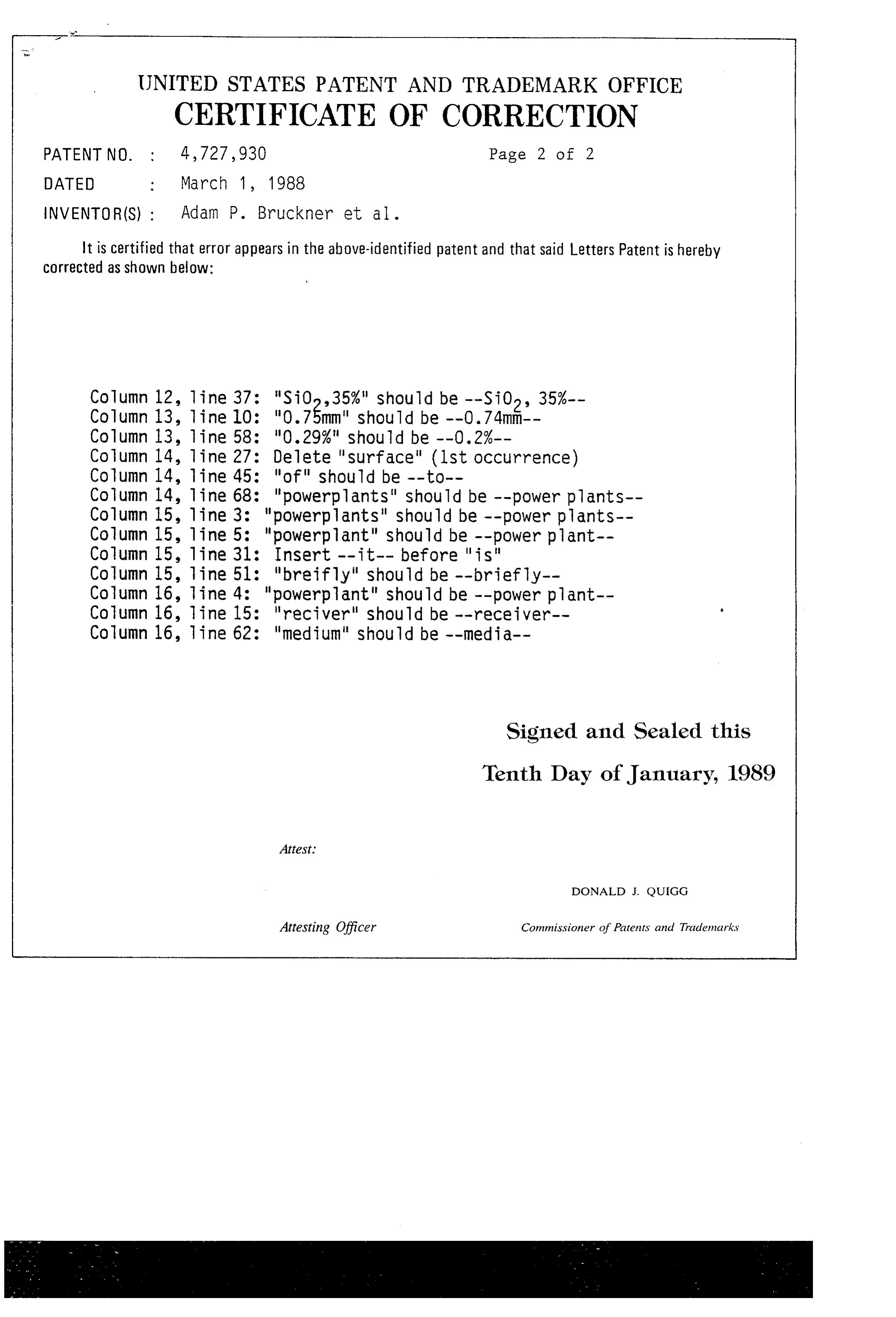
UNITED STATES PATENT AND TRADEMARK OFFICE
CERTIFICATE OF CORRECTION
PATENT NO. 4,727,930 Page 2 of 2
INVENTOR (S) : Adam P. Bruckner et al.
It is certified that error appears in the above-identified patent and that said Letters Patent is hereby Corrected as shown below:
Column 14, line 27: Delete "surface" (1st occurrence) Column 14, line 45: "of" should be --to--
Column 14, line 68: "powerplants" should be --power plants-- Column 15, line 3: "powerplants" should be --power plants-- Column 15, line 5: "powerplant" should be --power plant-- Column 15, line 31: Insert -- it-- before "is"
Column 15, line 51: "breifly" should be --briefly-- Column 16, line 4: "powerplant" should be --power plant-- Column 16, line 15: "reciver" should be --receiver.-- Column 16, line 62: "medium" should be --media--
Signed and Sealed this
Tenth Day of January, 1989
DONALD J. QUIGG
Attesting Officer Commissioner of Patents and Trademarks
Provenance
- Collection
- Cited prior art
- Original PDF
- patentimages.storage.googleapis.com →
- Filed
- 1981-08-17
- Pages
- 17
- Method
- pdftotext (the PDF's own text layer) + pdftoppm 300dpi page scans
- Source
- Google Patents bibliographic record
- Granted
- 1988-03-01
- Inventors
- Adam P. Bruckner; Abraham Hertzberg; David J. Shaw; University of Washington
- Transcribed from
- patentimages.storage.googleapis.com →