patent · US4258780
Dual cycle heat pipe-method and apparatus
31 March 1981
Page 1 — bibliographic record
United States Patent (19) (11) 4,258,780 Suo 45 Mar. 31, 1981 (54) DUAL CYCLE HEAT PIPE-METHOD AND ployed a dual cycle system for heating and cooling is APPARATUS disclosed. In the preferred embodiment, upper and lower heat transfer fluid conduits containing a first heat (75) Inventor: Mikio Suo, Ellington, Conn. transfer fluid are connected by heat pipes containing a 73) Assignee: United Technologies Corporation, second heat transfer fluid, the two fluids being isolated Hartford, Conn. from one another. The heat pipes are preferably sealed (21) Appl. No.: 972,598 plastic tubes with hollow metal end caps at each end. The metal end caps on the heat pipes are positioned in 22 Filed: Dec. 22, 1978 the circulation pipes so as to have sufficient contact 51 Int. Cl......................... F25B 27/02; F25B 13/00 with the recirculatory fluid in the respective heat trans 52 U.S. Cl. .......................................... 165/2; 62/260; fer fluid conduits to transfer heat to and from such fluid. 62/435; 62/333; 165/45; 165/105; 62/238.6 In the summer, heated fluid flows through the lower 58 Field of Search ............................. 165/45, 105, 2; conduit causing the second heat transfer fluid in the 62/238 E, 260, 324, 333, 435 lower end cap of the heat pipe to boil and condense on 56) References Cited the heat pipe wall giving off heat to the ground or other heat sink, thereby providing a cooling action on the first
2,749,724 6/1956 Borgerd et al. ................... 165/45 X In winter, the lower conduit is shut down and the upper 2,780,415 2/1957 Gay ............... ... 165/105 X conduit activated by passing cooled first heat transfer 3,563,304 2/1971 McGrath ........................... 165/45 X fluid through the upper conduit which condenses the 4,042,012 8/1977 Perry et al......................... 165/45 X second heat transfer fluid in the upper end cap causing Primary Examiner-Albert W. Davis it to flow by gravity down the walls of the heat pipe to Attorney, Agent, or Firm-Harry J. Gwinnell a point at which it boils and the resulting vapor then 57 ABSTRACT goes back up the heat pipe as a vapor, repeating the cycle and resulting in the heating of the first heat trans
A method and apparatus for utilizing the earth or other fer fluid in the upper conduit. Such a system can be used heat source/heat sink for heating and cooling buildings to both heat and cool buildings. are disclosed. The system comprises at least one heat transfer fluid conduit and at least one heat pipe in heat transfer communication. When two conduits are em 17 Claims, 5 Drawing Figures
---- - ---- /7
---------- w a3.
21S t SH2 SAs %ss a2 22 SS7. lm''. - - - - - - 52 SW6%\, V
Page 2
Drawing sheet — no readable text.
Page 3
Drawing sheet — no readable text.
Page 4
fected by simply limiting the flow of the first heat trans
DUAL CYCLE HEAT PIPE-METHOD AND fer fluid to either the lower or upper conduit, respec APPARATUS tively. In conjunction with conventional heat pump apparatus, the use of such systems can realize substantial
CROSS REFERENCE TO RELATED 5 savings in costs of heating and cooling building struc
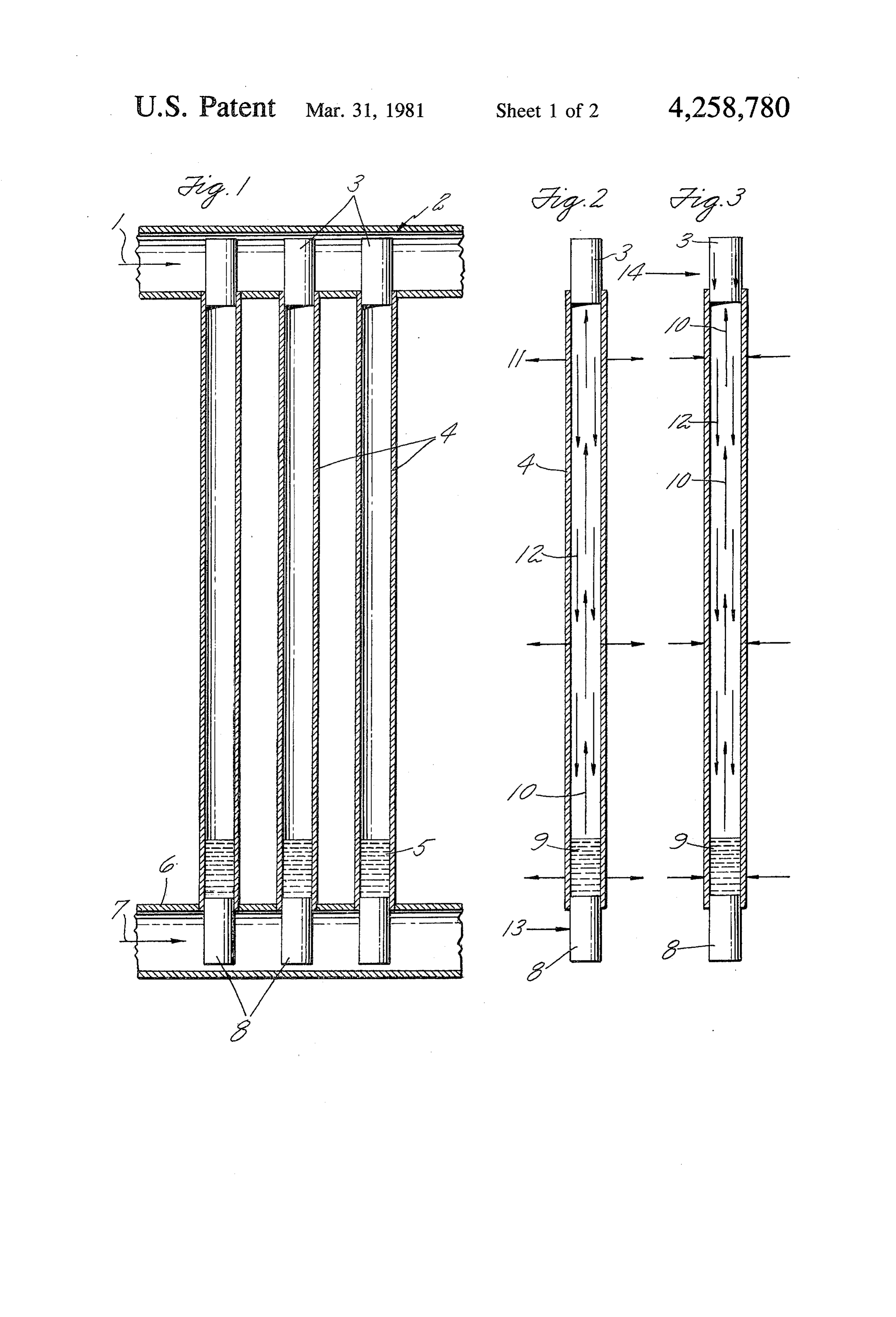
Attention is directed to Ser. No. 972,599, of common The foregoing and other objects, features and advan assignee, filed of even date herewith, entitled "Heat tages of the present invention will become more appar Pipe Bag System' which teaches a method of heating ent in light of the following detailed description of and cooling buildings through the use of a heat pipe 10 preferred embodiments, thereof as discussed and illus system. trated in the accompanying drawings. BACKGROUND OF THE INVENTION BRIEF DESCRIPTION OF THE DRAWINGS 1. Field of the Invention FIG. 1 is a vertical section of a heat pipe-circulation The field of art to which this invention pertains is 15 pipe system of the present invention. heat exchange utilizing an intermediate fluent material FIG. 2 is a vertical section of the heat pipe demon for receiving and discharging heat based on a condens strating its cooling cycle.
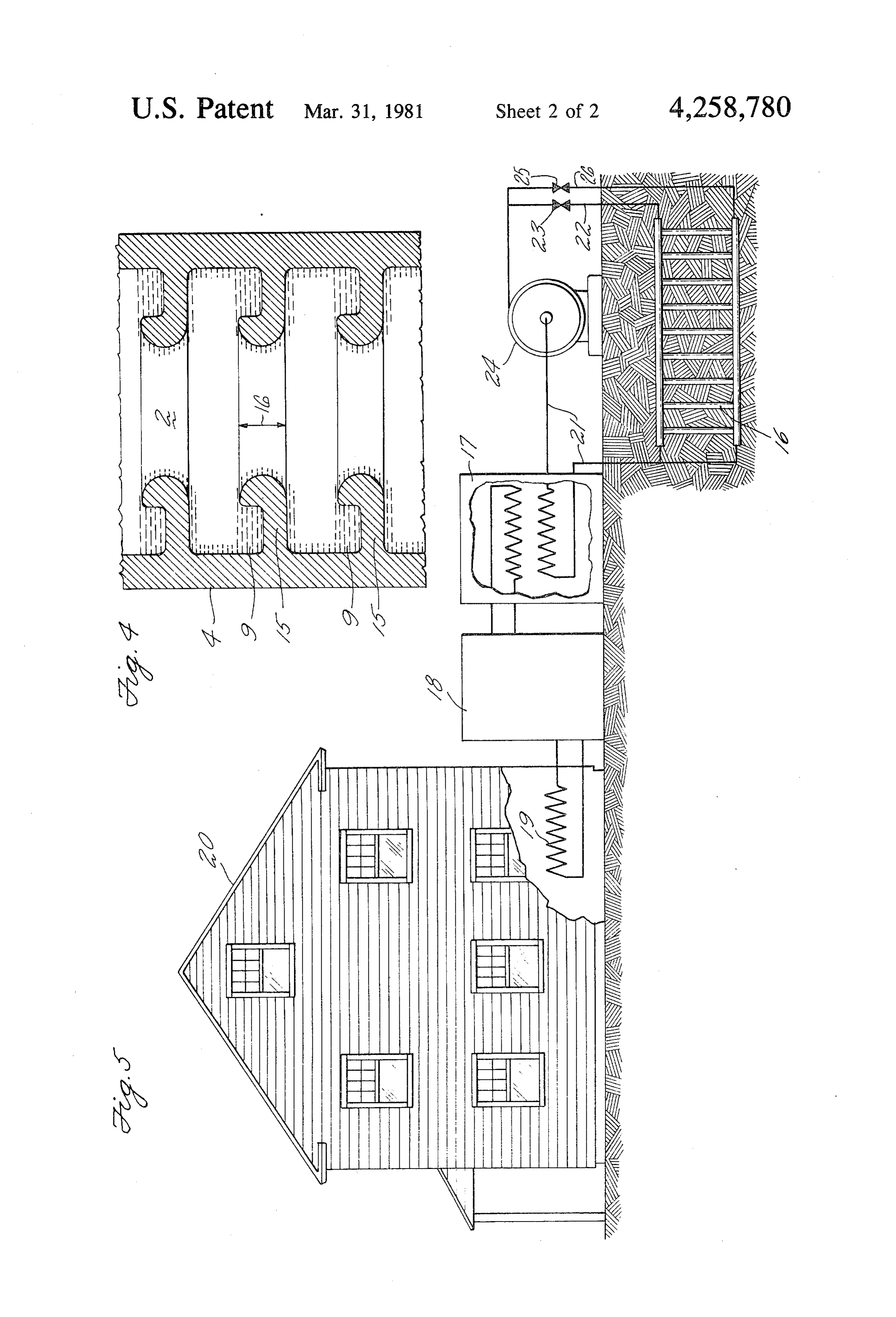
ing and evaporating system. FIG. 3 is a vertical section of the heat pipe demon 2. Description of the Prior Art strating its heating cycle.
It has been proposed to utilize a heat pipe system to 20 FIG. 4 demonstrates a preferred embodiment of the provide heating and cooling to residential buildings and internal condensation surface of the heat pipe. other similar structures. For example, the use of heat FIG. 5 illustrates the heat pipe system in use with a pipes in conjunction with furnace, hot water, and fire residential dwelling or other building structure. place systems has been suggested (Heat Pipe Theory And
Practice, by S. W. Chi, p. 219). It has also been proposed 25 DESCRIPTION OF THE PREFERRED to use the relatively constant temperature of the earth as EMBODIMENT a source of heating and cooling with various heat pipe Exemplary apparatus demonstrating the instant in systems. For example, U.S. Pat. No. 4,042,012 discloses vention comprises upper and lower circulation pipes a heat pump-heat pipe system utilizing the earth as the connected by heat pipes. The heat pipes are preferably heat source and heat sink with heat pipes buried in a 30 plastic but can be metal or any other material which can hole and surrounded by water-soaked absorbent poly withstand prolonged below ground exposure. While a mer particles; U.S. Pat. No. 2,749,724 utilizes a heat variety of designs are possible, it is of course critical pump and coil arrangement to take advantage of the that the interior of the first heat transfer fluid conduit be earth's temperature constant to heat a residential dwell in heat transfer communication with the heat pipes. ing; and U.S. Pat. No. 3,563,304 discloses a heat ex 35 While a variety of designs are possible to accomplish change system for providing refrigeration to a building this end, tubular heat pipes with sealed heat transfer structure where part of the heat exchange system may ends extending into the fluid conduits are preferred. be buried in the ground.
However, what has been lacking in the prior art is an Suchpipes, heat transfer surfaces present at the ends of the efficient method of utilizing the stored heat in the earth heat will function as boilers and condensers. As or other heat source/heat sink in a heat exchange sys the heat pipespreferred stated, in the form the heat transfer surfaces of extend at least partway into the circula tem which is both efficient and yet relatively simple in tion pipes. If the heat pipes are, for example, metal the structure to make its use economically feasible.
heat pipe ends can be a mere extension of the material
BRIEF SUMMARY OF THE INVENTION 45 the heat pipe is composed of. But, if plastic or other less The present invention overcomes the difficulties in conductive material is used, then a composite end cap utilizing the constant temperatures of a relatively con arrangement is preferred.
stant temperature heat source/heat sink such as the The heat pipe ends can be the same or different mate earth for heating and cooling buildings in conjunction rial at each end and can be of almost any usable shape. with conventional heat pumps and further overcomes 50 While the cup shape is preferred, finned or other similar the generally low thermal conductivity of the ground design is also possible. The heat pipe ends and plastic which requires an extensive distribution or collection pipe represent a closed, sealed system filled with the system in the prior art. According to the present inven liquid and vapor of a second heat transfer fluid. It is tion, a dual cycle, gravity driven heat pipe of simple important that the interior of the first heat transfer fluid operation and design is described to distribute heat to or 55 conduit be in fluid isolation from the interior of the heat collect heat from the ground. The heat transfer system pipe, and the seal end cap arrangement above accom described comprises at least one of an upper or lower plishes this. As stated, the heat pipe ends or end caps heat transfer fluid conduit having attached thereto at preferably extend into the circulation pipes on either least one gravity driven heat pipe to operate on a first end of the preferred plastic heat pipes where the ulti heat transfer fluid which passes through the conduit. mate first heat transfer fluid passes and contacts and are The gravity driven heat pipe contains a second heat at least partially covered by the first heat transfer fluid transfer fluid. The interior of the conduit is in heat in the circulation pipes. In most operating instances the transfer communication with the heat pipes and the first heat transfer fluid will substantially fill the circula interiors of the heat pipes and conduits are in fluid isola tion pipes as it passes through the heating or cooling tion from each other. In the dual cycle embodiment, 65 system. So in most cases even slight intrusion of the both upper and lower first heat transfer fluid conduits metal end caps of the heat pipes into the circulation are presently connected by common heat pipes and pipes will be sufficient to cause the necessary heat trans either an air-conditioning or heating mode can be ef fer for an efficient apparatus and method. However, the
Page 5
degree of intrusion of the end caps into the heat pipe and size to accomplish the purposes of the invention and will depend on a number of factors such as flow rates, would be well within the purview of one skilled in this specific first heat transfer fluid heat transfer properties,art. The circulation pipes may be any suitable material etc., calculable by one skilled in this area. Preferably, to convey the first heat transfer fluid such as metal or the end caps will be of sufficient length so as to extend 5 plastic. Similarly, the metal end caps functioning as almost completely into the entire diameter of the recir condensers and boilers may be any metal suitable for culation pipe. Note, e.g., FIG. 1. such use provided they have such properties as resis In the air-conditioning cycle, the upper circulation tance to corrosion to the heat transfer fluids and high pipe would be closed off and the first heat transfer fluid thermal conductivity, such as aluminum or copper. from the heat pump unit would flow through the lower 10 Preferably the metal end caps are hollow, tubular circulation pipe transferring heat from the first heat shaped pieces with metal seals at the ends, resembling transfer fluid to the second heat transfer fluid through metal cups and secured to plastic heat pipes forming a the lower metal end cap functioning in its boiler capac closed, sealed system. While the preferred configura ity. The second heat transfer fluid thus heated would tion of the end caps is sealed, hollow and tubular, as boil and the vapor would rise in the plastic tube. The 15 noted above other configurations may be used. The cup vapor would condense on the walls of the heat pipes or cap shape of the boilers and condensers in the pre transferring the heat from the second heat transfer fluid ferred heat pipe provides for an improved heat transfer to the ground or other heat sink. The thus cooled vapor surface. For example, the second heat transfer fluid would flow as a liquid by gravity alone back to the liquid condensing in the heat pipe can collect in the lower end cap functioning as a boiler to extract more 20 bottom of the end cap in a small pool and receive heat heat from the first heat transfer fluid in the air-condi from the bottom and sides of the end cap simulta tioning cycle. The thus cooled first heat transfer fluid neously, providing for more efficient heat transfer than would pass back to the air-conditioning system provid for example, a solid metal cylindrical end cap. But if for ing cool air to the residential dwelling or other building any particular consideration other shapes would be structure and once extracting warmth from the air in 25 desired, solid, plate-shaped or any workable design the dwelling would continue once again through the would be acceptable as long as the particular design lower circulation pipe and continue the cycle. provides for a closed seal when secured to the plastic or In the heating cycle, the lower circulation pipe would other material of the heat pipe tube. be closed off and the first heat transfer fluid would pass The end caps must be secured to the heat pipes, as through the upper circulation pipe in the system. The 30 stated above, so as to result in a sealed, closed system first heat transfer fluid in the upper pipe would be at for the second heat transfer fluid in the heat pipe tube. such a temperature to cause condensation of the vapors This may be accomplished in many ways, for example, on the upper metal end cap functioning as a condenser by molding or heat shrinking a plastic tube on the end thus forming a liquid from the second heat transfer caps or using other means, mechanical or chemical (e.g. vapors and extract heat from the second heat transfer 35 adhesives) to secure the end caps to the plastic or other fluid vapors. The second heat transfer fluid liquid thus material of the heat pipe tubes. It should also be noted formed by condensation would flow by gravity down that the insertion of the heat pipe with metal end caps the walls of the heat pipe. As the condensate flows into the circulation pipe should be performed in such a down the walls of the heat pipes, it would boil by virtue way as to result in a seal between the heat pipe and the of the residual heat within the earth. The resulting 40 circulation pipe to prevent any leakage of the first heat vapor would go back up the heat pipe as a vapor and transfer fluid from the circulation pipe, e.g., into the recondense on the upper metal end cap functioning as a heat pipe. Again, this may be accomplished by any condenser as a result of the heat and energy extracted conventional mechanical or chemical means including from the vapor by virtue of the cooled upper metal end molding and the use of conventional sealer material. caps, cooled by the first heat transfer fluid passing 45 If the preferred plastic heat pipes are used, the plastic through the upper circulation pipe. The warmed first of the heat pipes may be any suitable polymeric material heat transfer fluid passing by the upper metal end cap which resists corrosion from and is impervious to sec would return to a heat pump providing warmth to heat ond heat transfer liquid and vapor within the heat pipes, the building structure. such as high density polyethylene. Any number of heat As shown in FIG. 1, the invention basically com- 50 pipes may be used in the disclosed system and such prises a system of circulation pipes and heat pipes of number would be governed by such factors as the size simple and efficient design, the essence of which is of the recirculation pipes, the rate of flow of the first gravity driven. The system is a dual cycle systern being heat transfer fluid being passed by the heat transfer capable of supplying a low temperature heat sink for a surfaces, the size of the dwelling being heated or cooled heat pump unit operating in an air-conditioning mode 55 and other such general thermodynamic considerations and a source of heating for a heat pump operating in a within the purview of one skilled in the art. Preferably, heating mode to provide an aid to both the heating and the greatest efficiency can be achieved with two to four cooling of building structures such as residential dwell heat pipes per linear foot of circulation pipe. And as ings. In FIG. 1, the first heat transfer fluids 1 and 7 mentioned above, the second heat transfer liquid and which can be any fluid capable of transferring heat but 60 vapor may be any material or combination of materials preferably a liquid such as water or a waterethylene which will vaporize and condense around the working glycol mixture (preferably 50% water, 50% ethylene temperatures of the heat pipes at pressures near atmo glycol, by volume) passes through the respective circu spheric pressure, which temperatures will vary depend lation pipes 2 and 6 contacting either lower metal end ing on the temperature of the earth at the locality in caps functioning as boilers 8 or upper metal end caps 65 which the system is used. The temperature of the earth functioning as condensers 3 transferring heat to or from in most locations revolves around 55 F. (about 12.8 the second heat transfer fluids 5 in plastic heat pipes 4. C.) and thus the particular second heat transfer fluid The recirculation pipes 2 and 6 may be any diameter will be chosen with this temperature factor in mind. It
Page 6
should also be noted that while the first and second heat again by the end cap functioning as a boiler 8 heated by transfer fluids are preferably different materials, they the passing of first heat transfer fluid 13. can be the same heat transfer material. In FIG. 3, the reverse cycle is demonstrated. In this, In selecting a second heat transfer fluid, it is preferred the heating mode of operation of the heat pipe system, that the second heat transfer fluid have a vapor pressure 5 the first heat transfer fluid, for example water desig at or near atmospheric pressure (14.7 psi) at tempera nated as 14, cools the end cap functioning as a con tures between about 30 and 100 F. Freon (R) 11 (CCl3F) denser 3, causing the vaporized second heat transfer (E. I. du Pont de Nemours, Inc.) is such a heat transfer fluid 10 to condense on the end cap 3 by virtue of the fluid which was used as the second heat transfer fluid in temperature difference of the vapor and metal end cap. the system of the figures. Second heat transfer fluids 10 The first heat transfer fluid having given off its heat to with such properties will work effectively over all the heat pump to ultimately heat the residential dwell ground conditions in which the system will be used. If ing or other building structure returns in a cooled state to flow by the end cap functioning as a condenser ex the vapor pressure of the second heat transfer fluid over tracting the 30-100' F. temperature range is too far below atmo 15 heat energy from the vapors associated with spheric, the velocity of the vaporized second heat trans the end cap condenser and continues on in a warmed fer fluid would have to be impracticably high in order state to return heat to the heat pump. The condensed to transfer sufficient quantities of heat for an operable vapors 12 return as a liquid down the heat pipe toward system. Similarly, if the vapor pressure of the second the pool 9 at the bottom of the heat pipe and are contin ually vaporized as vapors 10 along the walls of the heat heat transfer fluid is too high over this temperature 20 pipe to be condensed on a continuing basis at the end range, the structure to contain the second heat transfer cap functioning as a condenser 3. In this mode, heat is fluid would have to be of such size and strength as to be supplied by the earth to cause the initial vaporization of impractical. the condensed fluid 9. As stated above, the second heat It is also important that there be sufficient liquid sec transfer fluid must be chosen to match the temperature ond heat transfer fluid in the heat pipes that even when 25 conditions prevalent at the earth site of operation of the operating in the most efficient mode where the liquid heat pipe. In such cases, a vapor-liquid condition con second heat transfer fluid is present and condensing tinually along the walls of the heat pipe along the entire length of whichever mode of operation is in usethat exists in the heat pipe system such by virtue of the heat pipe tube that there still be liquid second heat that is either the air-conditioning or heating mode,time, at the the transfer fluid present in the tube in contact with the 30 imbalance caused to occur by virtue of the heating of lower end cap such that continuous evaporation and the lower end caps functioning as boilers or cooling of condensation can take place. the upper end caps functioning as condensers will cause Since the temperature of the earth in most locations the second heat transfer fluid system to tend toward where this system will be used is about 55 F., in one equilibrium by virtue of the constant temperature of the embodiment of the system when it is operating in its 35 earth surrounding the heat pipe system. Accordingly, heating mode a second heat transfer fluid can be used in no changing of fluids is necessary in the heat pipe sys the heat pipe having a boiling point not exceeding 55 at tem regardless of which mode is in operation and the the vapor pressure conditions prevalent in the heat pipe mere shutting of valves to close off either the upper or under actual operating conditions, which in most cases, lower recirculation pipes are all that is necessary to take as indicated above, will be at or near atmospheric pres 40 advantage of the constant ground temperature and heat Se ing or cooling source continually present by virtue of In the specific system shown by FIG. 1, Freon 11 was the earth surrounding the heat pipes.
used as the second heat transfer fluid in the heat pipe. FIG. 4 is a vertical cross section demonstrating the The heat pipe of this figure was high density polyethyl preferred heat pipe design inside the plastic pipes 4 of ene 5 feet long with an outer diameter of 1 inch, and a 45 FIG. 1. In this preferred embodiment cup-shaped ribs wall thickness of 0.008 inch. In this particular example are designed into the plastic heat pipe to capture the the Freon was present in sufficient amount so as to condensed liquid 9 over the whole length of the heat completely fill the lower end cap prior to start up of the pipes. The ribs span the entire circumference of the system. pipe. The ribs 15 in the pipe 4 may either be molded into FIG.2 demonstrates the operation of the heat pipe in 50 the pipe or exist as a separate insert of a material, such the air-conditioning or gound heat sink mode. In such as metal or plastic. The height of the walls of the cups mode, the upper circulation pipe 2 of FIG. 1 is closed indicated as 16, may also vary depending on the amount off so that only the lower circulation pipe 6 of FIG. 1 and properties of the second heat transfer fluid and can would be in operation. Accordingly, the first heat trans be as small as desired to the point of representing no fer fluid, for example, water, as it comes from the heat 55 more than corrugations.
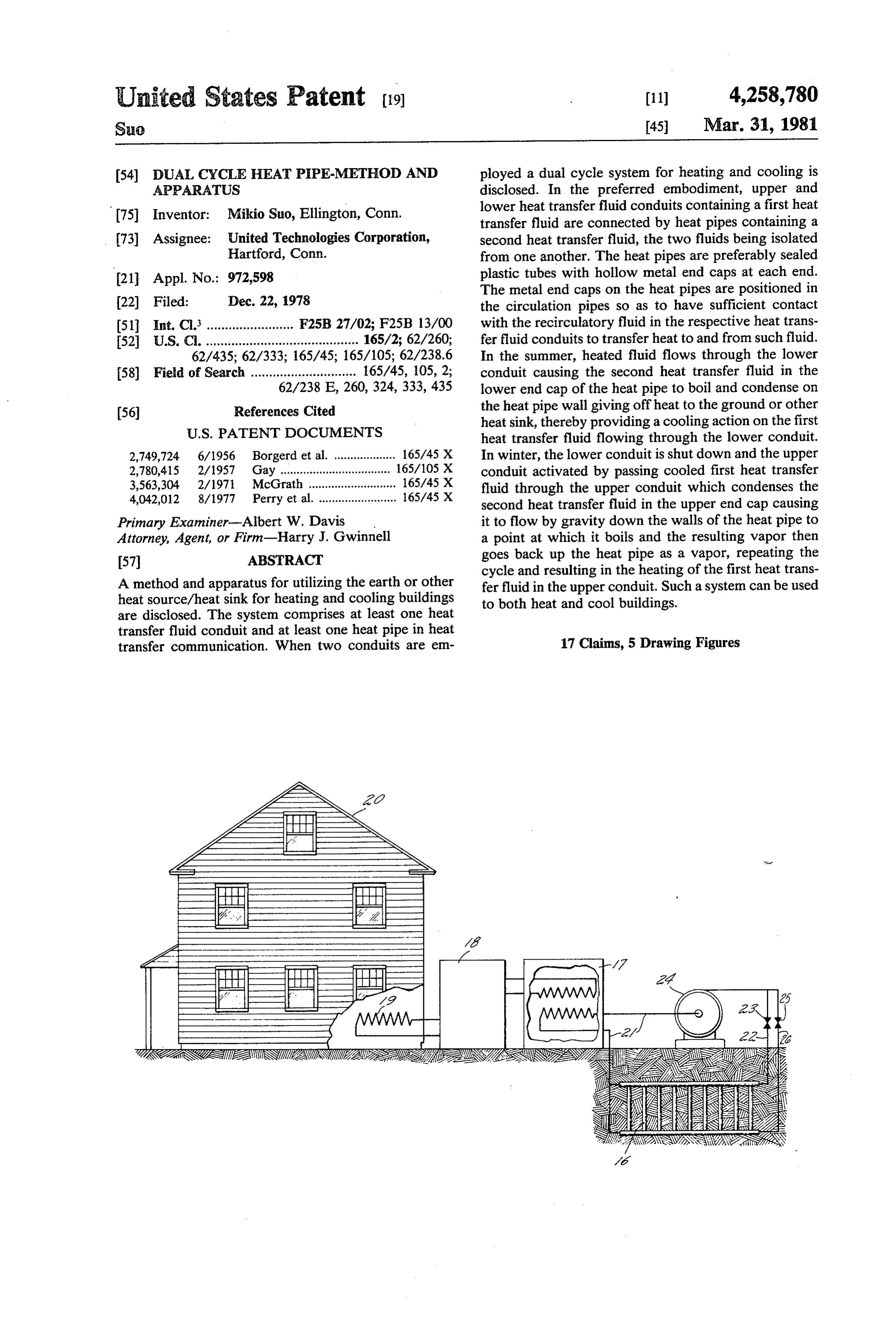
pump unit in a warmed condition having absorbed heat FIG. 5 demonstrates schematically the heat pipe sys from the unit, passes by lower end cap 8 giving off the tem 16 working in conjunction with a heat exchanger heat energy to such end cap operating in a boiler mode. 17, aheat pump 18, and a dwelling heat exchanger 19, to The first heat transfer fluid continues on in a cooled heat or cool the dwelling 20. For such a system, the first state having given off such heat energy and causes the heat transfer fluid circulates through the circulation second heat transfer fluid 9, for example, Freon 11, to pipes 21, 22 and 26, controlled by the valves 23 and 25, move up the heat pipe as a vapor 10 until it reaches and driven by the pump 24. In the air-conditioning points along the walls of the heat pipe 4 where it con mode, valve 23 is closed and valve 25 opened restricting denses giving off heat to the earth by virtue of the the flow of the first heat transfer fluid through circula cooler temperatures of the ground surrounding the heat 65 tion pipe 26. The heat which is absorbed by the first pipe (such heat out indicated as 11). The condensed heat transfer fluid in the heat exchanger 17 is given up second heat transfer fluid 12 continues back down the to the ground through the heat pipe system 16. Also in heat pipe 4 returning as a liquid 9 to be vaporized once the air-conditioning mode, heat is absorbed by the
Page 7
iwelling heat exchanger 19 causing cooling of the 2. The heat pipe system of claim 1 wherein the heat welling and is given up in the heat exchanger 17 pipes are plastic cylinders sealed at each end by hollow, th."ough the action of the heat pump 18. In the heating metal end caps.
mode, valve 23 is open and valve 25 closed restricting pipes 3. The heat pipe system of claim 1 wherein the heat the flow of the first heat transfer fluid through circula are substantially parallel to each other. tion pipe 22. Heat is absorbed from the ground through heat pipesheat 4. The are pipe system of claims 1 or 3 wherein the substantially perpendicular to the heat the heat pipe system 16 and is given up in the heat ex transfer fluid conduits.
changer 17. Also, in the heating mode heat is absorbed 5. The heat pipe system of claim 2 wherein the plastic in the heat exchanger 7 and is given up in the dwelling 10 heat pipes contain corrugated ribs along the internal heat exchanger 19 through the action of the heat pump circumference of the plastic pipes.
18, causing heating of the dwelling. 6. The heat pipe system of claim 2 wherein the plastic From the drawings and the remainder of the disclo heat pipes contain cup-shaped ribs along the internal sure, it can be seen that what has been invented is an circumference of the plastic heat pipe. efficient, simple heat pipe heating and cooling system 15 7. The heat pipe system of claim 2 wherein the plastic with no moving parts utilizing gravity as the driving tube is high density polyethylene.
force for transferring and absorbing heat to and from 8. The heat pipe system of claim 2 wherein at least the heat transfer fluids involved. Accordingly, not only one metal end cap is aluminum.
is energy saved based on the lessened degree of heating 9. The heat pipe system of claim 2 wherein at least and cooling required by the heat pump unit working in 20 one10.metal end cap is copper. The heat pipe system of claims 1 or 2 wherein at its heating and air-conditioning modes in the residential least one heat transfer fluid is a fluorinated hydrocar dwelling or other building structure, but energy is also bon.
saved by using gravity as the driving force in the heat 11. The heat pipe system of claim 10 wherein the pipe system. Furthermore, the same system can be used 25 fluorinated hydrocarbon comprises CC13F. for either heating or cooling providing even greater simplicity. This clearly provides a myriad of advantages ond heat transferpipe 12. The heat system of claim 1 wherein the sec fluid is a fluorinated hydrocarbon.
over conventional systems of the prior art (for example 13. The heat pipe system of claims 1 or 2 wherein the wick systems) which have countless problems. heat pipe is approximately five feet long, has an approxi Although this invention has been shown and de 30 mately one inch outer diameter, and the walls are ap scribed with respect to a preferred embodiment thereof, proximately 0.008 inch thick.
it should be understood by those skilled in the art that 14. The heat pipe system of claims 1 or 2 wherein various changes and omission in the form and detail there is sufficient liquid refrigerant in the heat pipes thereof may be made therein without departing from such that when there is liquid refrigerant condensate the spirit and scope of the invention. 35 along the entire length of the heat pipe walls, there is Having thus described a typical embodiment of my still liquid refrigerant at the bottom of the heat pipe. invention, that which I cliam as new and desire to se 15. The heat pipe system of claims 1 or 2 wherein cure by Letters Patent of the United States is: there are two to four heat pipes present per linear foot 1. A dual cycle, gravity driven heat pipe system com of 16. circulation pipe.
A method of heating and cooling a building struc prising upper and lower heat transfer fluid containing ture with a conventional heat pump circulation pipe conduits connected by a series of gravity driven heat system containing a first heat transfer fluid, the im pipes, the ends of said heat pipes extending into substan provement comprising at least partially heating or cool tially the entire internal diameter of said fluid contain ing the heat transfer fluid in the circulation pipe by ing conduits, the heat pipes containing a second heat 45 passing said fluid in a fluid circulation pipe of the appa transfer fluid in fluid isolation from the first heat trans ratus of claims 1 or 2. fer fluid and having a vapor pressure at or near atmo 17. The method of claim 16 wherein the first heat spheric pressure at temperatures between about 30 F. transfer fluid is water or a mixture of water and ethy and 100 F., said system buried in the ground below the lene-glycol. k x k frost line and connected to a heat pump system. 50
Provenance
- Collection
- Cited prior art
- Original PDF
- patentimages.storage.googleapis.com →
- Filed
- 1978-12-22
- Pages
- 7
- Method
- pdftotext (the PDF's own text layer) + pdftoppm 300dpi page scans
- Source
- Google Patents bibliographic record
- Granted
- 1981-03-31
- Inventors
- Mikio Suo; United Technologies Corp
- Transcribed from
- patentimages.storage.googleapis.com →