patent · US2715190
Dual flow direct current linear electromagnetic pump
9 August 1955
Page 1
Drawing sheet — no readable text.
Page 2
United States Patent Office 2,715,190 Patented Aug. 9, 1955
Another object of the invention is to provide a linear direct current dynamoelectric machine having two con 2,715,190 duits containing electrically conductive fluid of separate fluid flow circuits with flow of fluid in one conduit caus
DUAL FLOW DIRECT CURRENTLINEAR ing flow of fluid in another conduit and with the con ELECTROMAGNETIC PUMP duits arranged in heat exchange relation with each other. Edward F. Brill, Brookfield, Wis., assignor to Allis Other objects and advantages will be apparent to one Chalmers Manufacturing Company, Milwaukee, Wis. skilled in the art upon reading the following description With the accompanying drawing, in which:
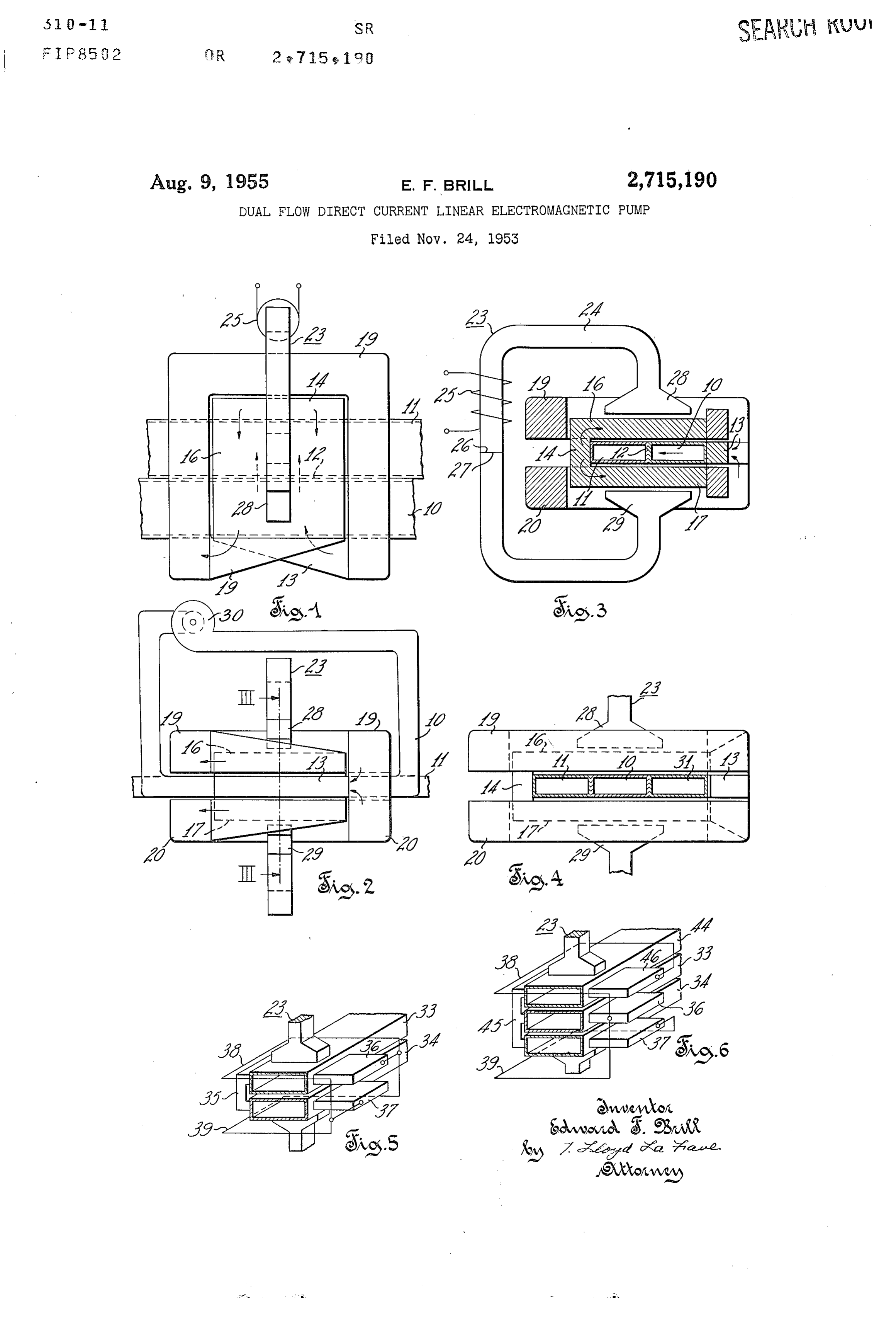
Application November 24, 1953, Serial No. 393,985 O Fig. 1 is a plan view of a direct current linear dynamo 9 Claims. (C. 310-11) electric machine embodying the present invention; Fig. 2 is a view in elevation of the machine shown in Fig. 1;
This invention relates to a dynamoelectric machine Fig. 3 is a cross sectional view taken along the line III-III of Fig. 2;
having two or more conduits containing electrically con Fig. 4 is an end view of a modification of the machine ductive fluid of separate fluid flow systems. More par shown in Fig. 1;
ticularly, the fluid in one conduit serves as the armature Fig. 5 is a view partly isometric and partly schematic portion of the dynamoelectric machine acting as a direct of another direct current linear dynamoelectric machine current linear electromagnetic generator and the fluid in : embodying the present invention; and another conduit serves as the armature portion of the Fig. 6 is a view partly isometric and partly schematic dynamoelectric machine acting as a direct current linear of another direct current linear dynamoelectric machine electromagnetic pump. embodying the present invention. Dynamoelectric machines operable as direct current The drawing shows a linear direct current dynamo linear electromagnetic generators or electromagnetic electric machine having a plurality of conduits for con pumps heretofore have been proposed as separate inde taining electrically conductive fluid of a plurality of sepa pendent machines. The dynamoelectric machine, accord rate fluid flow circuits. Fluid in conduits 10 and 11 serve ing to the present invention, comprises a generator and a as liquid armatures for the machine. Electric current is pump constructed of common elements in a unitary struc generated in moving armature fluid of conduit 10 and ture. The conductors providing current compensation this current is supplied to the armature fluid of conduit and series excitation are common to both generator and 11. Series excitation and current compensation are pro pump whose armatures are connected in series. The fluid vided which are common to both armatures. The dyna flowing in the generator conduit causes flow of fluid in moelectric machine therefore operates simultaneously as a pump conduit. The relative direction of fluid flow in electromagnetic generator and electromagnetic pump so the generator and pump conduits is determined by the 3 5 that fluid moving through conduit 10 causes pumping of relative directions of the armature current through the fluid in conduit 11.
fluids. Conduits 10 and 11 are disposed side by side and are The pumping effected by the dynamoelectric machine joined by an electrode 12 within the throat or armature may be regulated by varying the flow of fluid through the portion of the machine. Electrode 12 may be defined by generator conduit. This arrangement permits the isola 40 a common Wall for the adjacent conduits or as shown tion of a fluid flow system. It permits pumping fluid in by adjacent walls joined by Welding. An electrode 13 is isolated systems by means of another fluid flow system Suitably secured to conduit 10, and an electrode con coupled thereto through the generator and motor action ductor 14 is suitably secured to conduit 11. The elec of the direct current linear dynamoelectric machine. The rodes 12, 13, 14 are disposed to pass armature current dynamoelectric machine may be constructed for very high in the same direction through the fluids of both conduits. temperature operation and therefore may be used as a The conduits are preferably of high ohmic resistance pump for a high temperature electrically conductive fluid material such as stainless steel, so that current flow system and simultaneously as a heat eXchanger therefor. between electrodes is primarily through the fluid which The dynamoelectric machine may be used to isolate and has a relatively low ohmic resistance. operate other closed fluid systems such as a fluid system 50 Compensation for armature reaction is provided by which is dangerously radioactive or highly corrosive. conductor i6 disposed above conduits 10, 11 and by con It is therefore an object of the present invention to ductor 17 disposed below the conduits. Compensation provide a linear direct current dynamoelectric machine conductors 16 and 17 are connected to electrode 14 for having a plurality of liquid armatures with fluid flow conducting armature current in parallel paths above and through one armature generating electric current therein below the conduits in a direction opposite its direction which causes fluid to flow through another armature. through the armatures.
Another object of the invention is to provide a linear Series excitation is provided by a conductor turn adja dynamoelectric machine having two or more conduits cent the armatures. Such turn is effected by a conductor containing electrically conductive fluid of separate hydrau 19 arranged in a loop surrounding compensating conduc lic systems with fluid flow in one conduit causing fluid 60 for 16 above the conduits and by a conductor 20 arranged flow in another conduit. in a loop surrounding conductor 17 below the condits. Another object of the invention is to provide a linear Conductor 19 has one end connected to electrode 13 and direct current dynamoelectric machine electromagneti its other end connected to compensation conductor 16 on cally associated with two or more independent fluid flow the same side of the conduits. Conductor 20 has one end circuits with fluid flow in one circuit causing fluid flow connected to electrode 13 and its other end connected in another circuit. to compensation conductor 17 on the same side of the Another object of the invention is to provide a direct conduits.
current linear electromagnetic generator in combination Conductor 19 is thus connected in series with com with a linear direct current electromagnetic pump con pensation conductor 16 and the armatures. Conductor structed and arranged in a unitary structure having exci 70 20 is connected in series with compensation conductor tation and compensation conductors common to both gen 17 and the armatures. Conductors 19 and 20 thus pro erator and pump. vide parallel paths for the armature current in excitation
Page 3
loops above and below the conduits. This arrangement side of conduit 33, and an electrode conductor 37 is con effects a series conductor turn providing a magnetic field nected to the other side of conduit 34. through both armatures with lines of flux substantially A conductor 38 is connected across electrode conduc normal to the conduits and to the armature current and tors 36, 37 and is arranged in a loop above the super normal to the flow of the armature fluids. The conductor posed conduits forming a conductor turn about the arma turn effected is in the plane of symmetry of the conduits. ture portions of the conduits. Similarly, a conductor 39 The series excited and compensated dynamoelectric is also connected across electrode conductors 36, 37 and machine thus far described is a closed circuit electromag arranged in a loop below the superposed conduits. Con netic device without external electrical connection, and ductors 38, 39 effect a conductor turn about the arma () tures of the conduits.
without an iron core. Means applying an E" netic field for starting generator action comprisis re Pole pieces of removable electromagnet 23 are also movable electromagnet 23 having a C-shaped core 24 and Surrounded by the loops formed by conductors 38, 39. a coil 25 disposed thereon for exciting the core - when In operation, fiuid is forced in one direction through energized from a source of direct current, not 'shown. conduit 33, and this moving fluid cuts lines of flux there The core 24 may be made in two sections having ends 26, in to generate armature current which flows in series 27 abutting each other and hinged together to aid in through the armature fluid in conduit 34 and through the placing in position or removing from the machine. Pole parallel connected excitation loops formed by conductors pieces 28, 29 of the electromagnet are disposed above and 38, 39.
below, respectively, of the armature portion of at least Armature current energizes the conductor turn to pro conduit 10. Pole pieces may extend as shown over the vide a magnetic field in series through the superposed armature portions of both conduits. Pole pieces in the conduits.
position shown are encircled by the loops formed by con The current flows in one direction through the arma ductors 19 and 20, respectively. ture fluid of conduit 33 and in the opposite direction In operation, fluid is forced in one direction through through the armature fluid in conduit 34. The opposite conduit 10 by suitable known means such as by centrif 5 direction of current flow in these two superposed ar ugal pump 30 shown in Fig. 2. This moving fluid cuts matures compensate for armature reaction in one another lines of flux produced by energization of electromagnet So that additional compensating current conductors are 23. As a result, electric current is generated in the mov not employed.
ing fluid. This current circulates in the closed series cir Current through the fluid in conduit 34 reacts with the cuit as indicated by arrows in Figs. 1 to 3, energizing the flux therein to force the fluid in conduit 34 to flow in conductor turn effected by conductors 19 and 20 and sup the same direction as the fluid in conduit 33. By means plying current to the armature fluid in conduit 11. The of the electromagnetic generator and pump, therefore, energized conductor turn produces a magnetic field controlled fluid flow in conduit 33 causes controlled through the armature fluids of conduits 10 and 11 which fluid flow in the same direction in conduit 34. lie in parallel paths in the magnetic circuit. 35 The embodiment of the invention shown in Fig. 6 is The armature current in the fluid of conduit 11 reacts a modification of the arrangement shown in Fig. 5 in with the magnetic field therein to force the fluid in con that three, instead of two, superposed conduits are em duit 11 to flow in a direction opposite the direction of ployed. Additional conduit 44 contains electrically flow of the fluid in conduit 10. conductive fluid also serving as an armature for the ma Thus, moving armature fluid in conduit 10, compensa 40 chine and is connected in series with armature fluid of tion conductors 16, 17, and series turn effected by con conduit 33 and in parallel with armature fluid of con ductors 19, 20 conduct the generated current in a series duit 34. Electrode conductor 45 electrically joins one circuit to operate the dynamoelectric machine as a di side of each conduit 44, 33, 34. Electrode conductor 46 rect current linear electromagnetic generator. The series Secured to the opposite side of conduit 44 is connected circuit also includes armature fluid in conduit 11 disposed 4 5 through loop conductor 38 to electrode conductor 36 between compensation conductors 16, 17 and within the for conduit 33. Loop conductor 39 remains connected magnetic field produced by the series turn effected by across electrode conductors 36, 37. Pole pieces of elec conductors 19, 20 so that the dynamoelectric machine tromagnet 23 are surrounded by the loops which effect operates as a direct current linear electromagnetic pump a conductor turn providing magnetic flux in series through forcing fluid flow in conduit 11. Means varying the flow the three superposed conduits. of fluid in the fluid flow system including conduit 10 Moving fluid in middle conduit 33 generates arma varies the flow of fluid in the separate fluid flow system ture current which divides to flow in parallel paths including conduit 11. through the armature fluid in the top and bottom con Fig. 4 shows the addition of a third conduit 31 to a duits 44 and 34. The currents through the top and bot machine like that shown in Figs. 1 to 3. Conduit 31 5 tom conduits serve as compensating current for arma contains electrically conductive fluid serving as another ture, reaction in the middle armature, and similarly the liquid armature for the machine. Conduit 31 is dis current through the middle conduit serves as compensat posed side by side with conduits 10 and 11 and connected ing current for armature reaction of the top and bottom electrically in series therewith between electrode con armatures.
ductors 13 and 14. Armature current generated in the CO Armature current in the fluid of the top and bottom fluid of conduit 10 is conducted by the fluid in conduit 31 conduits react to force the fluid therein to flow in the and reacts with the magnetic fleld therein to force the Same direction as the fluid flow in conduit 33. Thus fluid to flow in the direction of the fluid flow in conduit flow of fluid in conduit 33 by means of the dynamo 11 and in the opposite direction of the fluid flow in con electric machine forces fluid to flow in conduits 34, 44 duit 0. of separate fluid flow systems. In the embodiment of the invention shown in Fig. 5, Although but a few embodiments of the present inven the dynamoelectric machine comprises two superposed tion have been shown and described, it will be apparent conduits 33, 34 for containing electrically conductive fluid to one skilled in the art that various changes and modi of separate fluid flow systems. Adjacent faces of the con fications may be made therein without departing from duits are insulated from each other preferably by air 70 the spirit of the invention or from the scope of the ap space therebetween. Fluid in the conduits within a throat pended claims.
portion of the machine shown serves as liquid armatures It is claimed and desired to secure by Letters Patent: connected electrically in series by an electrode conductor 1. A multiple flow linear direct current dynamoelectric 35 secured to the left sides of conduits 33 and 34. An machine comprising a plurality of conduits each for con electrode conductor 36 is connected to the other or right taining electrically conductive fluid of separate fluid flow
Page 4
circuits, said fluid serving as armatures for said machine below said conduit adjacent both ends of said armature conducting armature current transversely of the fluid and wound about the adjacent said compensation con flow, a field conductor arranged to form a conductor ductors to form a conductor turn adjacent said armature, turn adjacent said armatures, means forcing fluid said field conductors, said armature and said compensa through one of said conduits, and means applying a mag 5 tion conductors connected in a closed series circuit effect netic field through the moving fluid to cause armature ing a conductor turn in the plane of symmetry of said current to be generated therein which flows through the armature with the axis of said turn normal to the direc fluid of another of said conduits and through the field tion of said armature current to produce a magnetic field conductor to produce a magnetic field through said arma through said armature, said compensation conductors tures which reacts with said armature current in said 10 dispose within said magnetic field and connected in other conduit to force said fluid to flow through said parallewith each other and in series with said armature other conduit. for conducting armature current in a direction through 2. A multiple flow linear direct current dynamoelectric said magnetic field opposite its direction in said armature, machine comprising a plurality of conduits each con whereby fluid flowing through one of said conduits causes taining electrically conductive fluid in separate fluid flow armature current to be generated in the moving fluid circuits, said conduits disposed side by side with said which current flows through said series circuit to cause fluid of said conduits serving as a common armature for electromagnetic pumping of the fluid through another of said machine with the armature fluids of said conduits said conduits.
conducting armature current in the same direction 5. A multiple flow linear direct current dynamo-electric through each of said conduits and transversely of the machine comprising a plurality of conduits each contain fluid flow therein, a compensating current conductor dis ing electrically conductive fluid of separate fluid flow posed adjacent the armature portion of said conduits, circuits, said conduits superposed with said fluid of said one end of said compensation conductor connected to conduits serving as armatures for said machine conduct one terminal of said armature, an excitation conductor ing armature current in one direction through one of said arranged in a turn about said compensation conductor 2 5 conduits and in the opposite direction through another of and connected between the other end of said compensa said conduits transversely of the fluid flow therein, a field tion conductor and the other terminal of said armature conductor forming a conductor turn about said armature, to conduct said armature current in a closed series circuit said field conductor connected in a closed series circuit through said armature, said compensation conductor and with said armature, armature current in said field con said excitation conductor, armature current in said exci ductor producing a magnetic field through said super tation conductor producing a magnetic field through said posed conduits transversely of said armature current and armature transversely of said armature current and of of said fluid flow, whereby fluid flowing through said one said fluid flow, whereby fluid flowing through one of of said conduits and means applying a magnetic field said conduits and means applying a magnetic field through the moving fluid to initiate generation of arma through the armature portion of said moving fluid to 3. 5 ture current therein, said series circuit conducting arma initiate generation of armature current therein, said ar ture current generated in said one conduit through said mature current in another of said conduits reacting with other conduit where said armature current reacts with said magnetic field to pump said fluid through said other said magnetic field to pump said fluid through said other conduit. conduit.
3. A multiple flow linear direct current dynamo-electric 40 6. A dual flow linear direct current dynamoelectric machine operable as an electromagnetic generator and as machine operable as an electromagnetic generator and as an electromagnetic pump comprising a plurality of con an electromagnetic pump comprising two superposed con duits disposed side by side for connection in separate duits for connection in separate fluid flow circuits, said fluid flow circuits, said conduits containing electrically conduits containing electrically conductive fluid serving conductive fluid serving as a common armature for the 45 as Superposed armatures for the generator and pump por generator and pump portions of said machine, a magnetic Itions of said machine, a magnetic core having poles spaced core having poles spaced apart by said armature to provide apart by said superposed armatures to provide a magnetic a magnetic field through said armature when said poles field through said superposed armatures when said poles are excited, compensation conductors disposed within are excited, said armatures connected in series with one said magnetic field above and below said armature, said armature conducting current in one direction through one compensation conductors connected in parallel with each conduit and the other armature conducting current in the other and in series with said armature for conducting opposite direction through the other conduit to cause the armature current in a direction through said magnetic current in one armature to compensate for the armature field opposite its direction through said conduits, a field reaction of the current in the other armature and vice conductor divided to cross above and below said conduits versa, a field conductor connected to said armatures and adjacent both ends of said armature and wound about the divided to cross above and below said conduits adjacent adjacent said compensation conductors to form a con both ends of said armatures and forming a conductor ductor turn about said armature, said field conductor, said turn about said poles, said field conductor and said arma armature and said compensation conductors connected tures connected in a closed series circuit to effect a con in a closed series circuit to effect a conductor turn about 60 ductor turn about armatures and said poles for producing said poles to provide series excitation for producing a a magnetic field through said armatures, whereby fluid magnetic field through said armature, whereby fluid flow flowing through one of said conduits causing armature ing through one of said conduits generates armature cur current to be generated therein which flows through said rent therein which flows through said series circuit to series circuit to cause electromagnetic pumping of the cause electromagnetic pumping of the fluid through the 65 fluid through the said other conduit. other said conduit. 7. A multiple flow linear direct current dynamoelectric 4. A multiple flow linear direct current dynamo-electric machine operable as an electromagnetic generator and as machine operable as an electromagnetic generator and as an electromagnetic pump comprising three superposed an electromagnetic pump comprising a plurality of con conduits for connection in separate fluid flow circuits, said duits for connection in separate fluid flow circuits, said 70 conduits containing electrically conductive fluid serving conduits containing electrically conductive fluid serving as armatures for the generator and pump portions of as a common armature for the generator and pump por said machine, the top and bottom said conduits serving tions of said machine, compensation conductors disposed as armatures for said pump portions of said machine and above and below said armature, a field conductor con fluid in the intermediate said conduit serving as the arma nected to said armature and divided to cross above and 75 ture for said generator portion of said machine, means
Page 5
connecting said pump armatures electrically in parallel one of said conduits generates current in said circuit with each other and in series with said generator arma means in the armature fluid thereof which current flows ture for conducting current in a direction through said through the armature fluid of another of said conduits top and bottom conduits opposite its direction through and reacts with said magnetic field therein to force said said intermediate conduit to cause the current in the pump fluid to flow in said other conduit. armatures to compensate for the armature reaction of 9. A linear direct current dynamoelectric machine com the current in the generator armature and vice versa, a prising a plurality of conduits for connection in separate field conductor connected to said armatures and divided fluid flow circuits containing electrically conductive fluid, to cross above and below said superposed conduits adja said fluid in said conduits serving as armatures for said cent both ends of said armatures and forming a conduc O machine, a field conductor arranged adjacent said arma tor turn adjacent said armatures, said field conductor and tures to form a conductor turn which when energized said armatures connected in a closed series circuit to produces a magnetic field through said armature fluids effect a conductor turn in the plane of symmetry of said transversely of the current and the flow therein, and means intermediate conduit with the axis of said turn normal including armature current compensation electrically to the direction of said armature current for producing a connecting the armature fluid of each said conduit to said magnetic field through said superposed armatures trans field conductor, whereby fluid flow through one of said versely of the fluid flow and of said current when said conduits generates current in the armature fluid thereof field conductor carries current, whereby fluid flowing in which current energizes said conductor turn to produce said intermediate conduit through said field causes cur said magnetic field and whereby said generated current rent to be generated therein which flows through said also flows through another of said conduits and reacts series circuit to provide field excitation and cause with said magnetic field therein to force said fluid to electromagnetic pumping of the fluid through said top flow through said other conduit. and bottom conduits.
8. A linear direct current electromagnetic device com References Cited in the file of this patent prising a plurality of conduits for connection in sepa UNITED STATES PATENTS rate fluid flow circuits containing electrically conductive fluid, said fluid in said conduits serving as armatures for 2,258,415 Lago ----------------- Oct. 7, 1941 said device, circuit means electrically connecting said 2,386,369 Thompson ------------- Oct. 9, 1945 armature fluids for conducting electric current through 2,612,109 Wakefield ------------- Sept. 30, 1952 the fluid in each said conduit transversely of the fluid flow 30 2,637,207 Boisblanc ------------- May 5, 1953 therein, said conduits disposed in a common magnetic 2,669,873 Gardner et al. --------- Feb. 23, 1954 field and means applying said magnetic field through the FOREIGN PATENTS armature fluid of each said conduit transversely of the 7,670 Great Britain ---------------- of 1902 current and fluid flow therein, whereby fluid flow through
Page 6
UNITED STATES PATENT OFFICE
CERTIFICATE OF CORRECTION
Patent No. 2,715,190 August 9, 1955 Edward F. Brill
It is hereby certified that error appears in the printed specification of the above numbered patent requiring correction and that the said Letters Patent should read as corrected below.
Column 8, line l3, after "flow" insert -- of fluid --.
Signed and sealed this llth day of October 1955.
(SEAL)
Attest:
E MRR. Y ROBERT. C. WATSON Attesting Officer - Commissioner of Patents
Provenance
- Collection
- Cited prior art
- Original PDF
- patentimages.storage.googleapis.com →
- Filed
- 1953-11-24
- Pages
- 6
- Method
- pdftotext (the PDF's own text layer) + pdftoppm 300dpi page scans
- Source
- Google Patents bibliographic record
- Granted
- 1955-08-09
- Inventors
- Edward F Brill; Allis Chalmers Corp
- Transcribed from
- patentimages.storage.googleapis.com →