patent · US4161164
Internal combustion engine fuel supply system
17 July 1979
Page 1 — bibliographic record
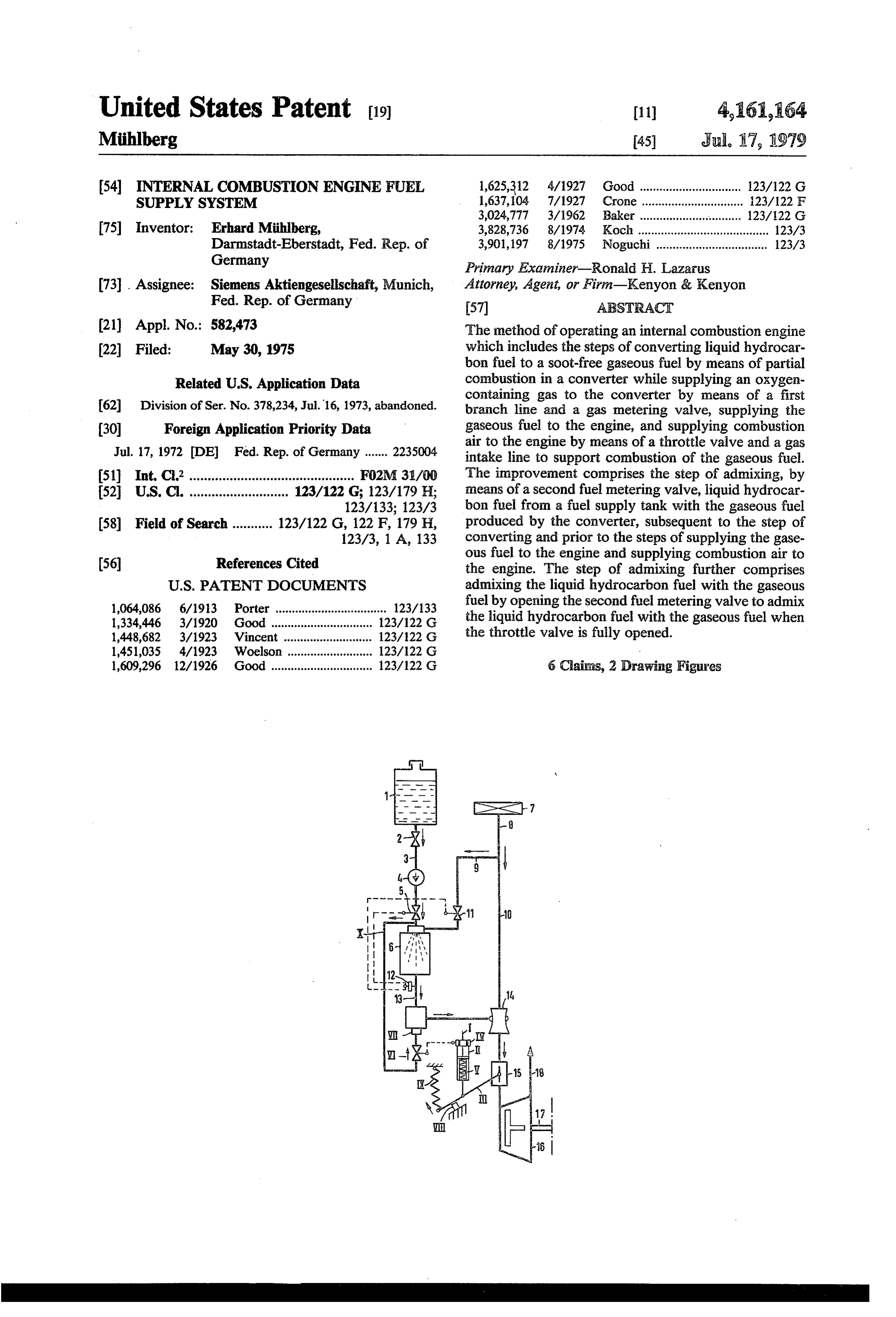
United States Patent (19) 11 4,161,64 Miihlberg 45) Jul, 17, 1979 54 INTERNAL COMBUSTION ENGINE FUEL 1,625,312 4/1927 Good ............................... 123/122 G SUPPLY SYSTEM 1,637,104 7/1927 Crone ............................... 23/22 F 3,024,777 3/1962 Baker ..... ... 123/122 G 75 Inventor: Erhard Miihlberg, 3,828,736 8/1974 Koch ........................................ 123/3 Darmstadt-Eberstadt, Fed. Rep. of 3,901,197 8/1975 Noguchi.................................. 123/3 Germany Primary Examiner-Ronald H. Lazarus 73 Assignee: Siemens Aktiengesellschaft, Munich, Attorney, Agent, or Firm-Kenyon & Kenyon Fed. Rep. of Germany (57) AESTRACT 21 Appl. No.: 582,473 The method of operating an internal combustion engine 22 Filed: May 30, 1975 which includes the steps of converting liquid hydrocar bon fuel to a soot-free gaseous fuel by means of partial
Related U.S. Application Data combustion in a converter while supplying an oxygen containing gas to the converter by means of a first 62 Division of Ser. No. 378,234, Jul.16, 1973, abandoned. branch line and a gas metering valve, supplying the 30 Foreign Application Priority Data gaseous fuel to the engine, and supplying combustion Jul. 17, 1972 DE Fed. Rep. of Germany ....... 2235004 air to the engine by means of a throttle valve and a gas intake line to support combustion of the gaseous fuel.
511 Int. C.’............................................. FO2M 31/OO The improvement comprises the step of admixing, by 52 U.S. C. ........................... 123/122 G; 123/179 H; means of a second fuel metering valve, liquid hydrocar 123/133; 123/3 bon fuel from a fuel supply tank with the gaseous fuel 58) Field of Search ........... 123/122 G, 122 F, 179 H, produced by the converter, subsequent to the step of 123/3, 1 A, 133 converting and prior to the steps of supplying the gase 56) References Cited ous fuel to the engine and supplying combustion air to the engine. The step of admixing further comprises
1,064,086 6/1913 Porter .................................. 123/133 fuel by opening the second fuel metering valve to admix 1,334,446 3/1920 Good ..... . 123/122 G the liquid hydrocarbon fuel with the gaseous fuel when 1,448,682 3/1923 Vincent ........................... 123/122 G the throttle valve is fully opened. 1,451,035 4/1923 Woelson .......................... 123/122 G 1,609,296 12/1926 Good ............................... 123/122 G 6 Cairns, 2 Drawing Figures
Page 2
Drawing sheet — no readable text.
Page 3
Drawing sheet — no readable text.
Page 4
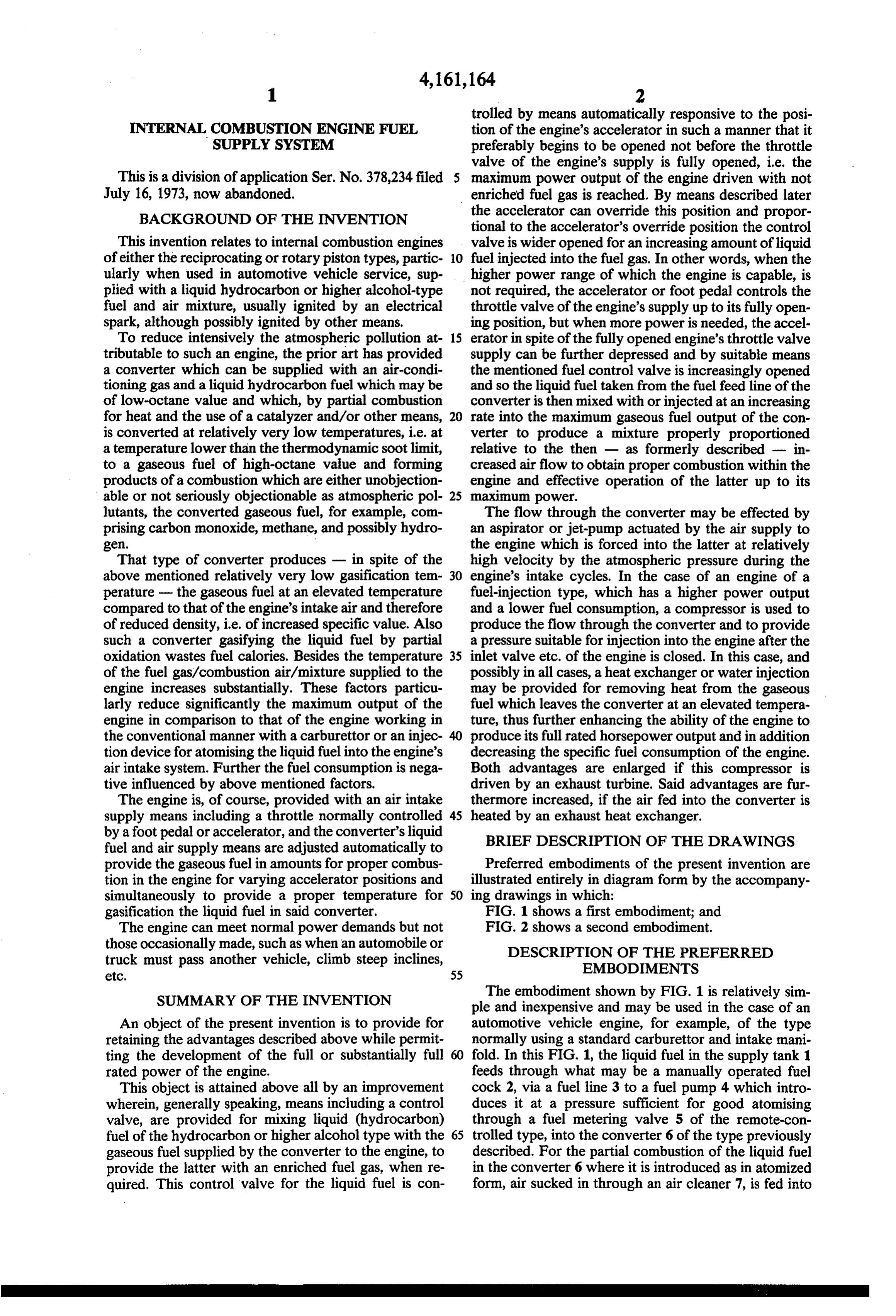
trolled by means automatically responsive to the posi
INTERNAL COMBUSTION ENGINE FUEL tion of the engine's accelerator in such a manner that it SUPPLY SYSTEM preferably begins to be opened not before the throttle valve of the engine's supply is fully opened, i.e. the
This is a division of application Ser. No. 378,234 filed maximum power output of the engine driven with not July 16, 1973, now abandoned. enriched fuel gas is reached. By means described later BACKGROUND OF THE INVENTION the accelerator can override this position and propor tional to the accelerator's override position the control
This invention relates to internal combustion engines valve is wider opened for an increasing amount of liquid of either the reciprocating or rotary piston types, partic 10 fuel injected into the fuel gas. In other words, when the ularly when used in automotive vehicle service, sup higher power range of which the engine is capable, is plied with a liquid hydrocarbon or higher alcohol-type not required, the accelerator or foot pedal controls the fuel and air mixture, usually ignited by an electrical throttle valve of the engine's supply up to its fully open spark, although possibly ignited by other means. ing position, but when more power is needed, the accel To reduce intensively the atmospheric pollution at 15 erator in spite of the fully opened engine's throttle valve tributable to such an engine, the prior art has provided Supply can be further depressed and by suitable means a converter which can be supplied with an air-condi the mentioned fuel control valve is increasingly opened tioning gas and a liquid hydrocarbon fuel which may be and so the liquid fuel taken from the fuel feed line of the of low-octane value and which, by partial combustion converter is then mixed with or injected at an increasing for heat and the use of a catalyzer and/or other means, 20 rate into the maximum gaseous fuel output of the con is converted at relatively very low temperatures, i.e. at verter to produce a mixture properly proportioned a temperature lower than the thermodynamic soot limit, relative to the then - as formerly described - in to a gaseous fuel of high-octane value and forming creased airflow to obtain proper combustion within the products of a combustion which are either unobjection engine and effective operation of the latter up to its able or not seriously objectionable as atmospheric pol 25 maximum power.
lutants, the converted gaseous fuel, for example, com The flow through the converter may be effected by prising carbon monoxide, methane, and possibly hydro an aspirator orjet-pump actuated by the air supply to gen. the engine which is forced into the latter at relatively That type of converter produces - in spite of the high velocity by the atmospheric pressure during the above mentioned relatively very low gasification tem 30 engine's intake cycles. In the case of an engine of a perature - the gaseous fuel at an elevated temperature fuel-injection type, which has a higher power output compared to that of the engine's intake air and therefore and a lower fuel consumption, a compressor is used to of reduced density, i.e. of increased specific value. Also produce the flow through the converter and to provide such a converter gasifying the liquid fuel by partial a pressure suitable for injection into the engine after the oxidation wastes fuel calories. Besides the temperature 35 inlet valve etc. of the engine is closed. In this case, and of the fuel gas/combustion air/mixture supplied to the possibly in all cases, aheat exchanger or water injection engine increases substantially. These factors particu may be provided for removing heat from the gaseous larly reduce significantly the maximum output of the fuel which leaves the converter at an elevated tempera engine in comparison to that of the engine working in ture, thus further enhancing the ability of the engine to the conventional manner with a carburettor or an injec produce its full rated horsepower output and in addition tion device for atomising the liquid fuel into the engine's decreasing the specific fuel consumption of the engine. air intake system. Further the fuel consumption is nega Both advantages are enlarged if this compressor is tive influenced by above mentioned factors. driven by an exhaust turbine. Said advantages are fur The engine is, of course, provided with an air intake thermore increased, if the air fed into the converter is supply means including a throttle normally controlled 45 heated by an exhaust heat exchanger. by a foot pedal or accelerator, and the converter's liquid BRIEF DESCRIPTION OF THE DRAWINGS fuel and air supply means are adjusted automatically to provide the gaseous fuel in amounts for proper combus Preferred embodiments of the present invention are tion in the engine for varying accelerator positions and illustrated entirely in diagram form by the accompany simultaneously to provide a proper temperature for 50 ing drawings in which:
gasification the liquid fuel in said converter. FIG. 1 shows a first embodiment; and The engine can meet normal power demands but not FIG. 2 shows a second embodiment. those occasionally made, such as when an automobile or DESCRIPTION OF THE PREFERRED truck must pass another vehicle, climb steep inclines, EMBODIMENTS etc. 55
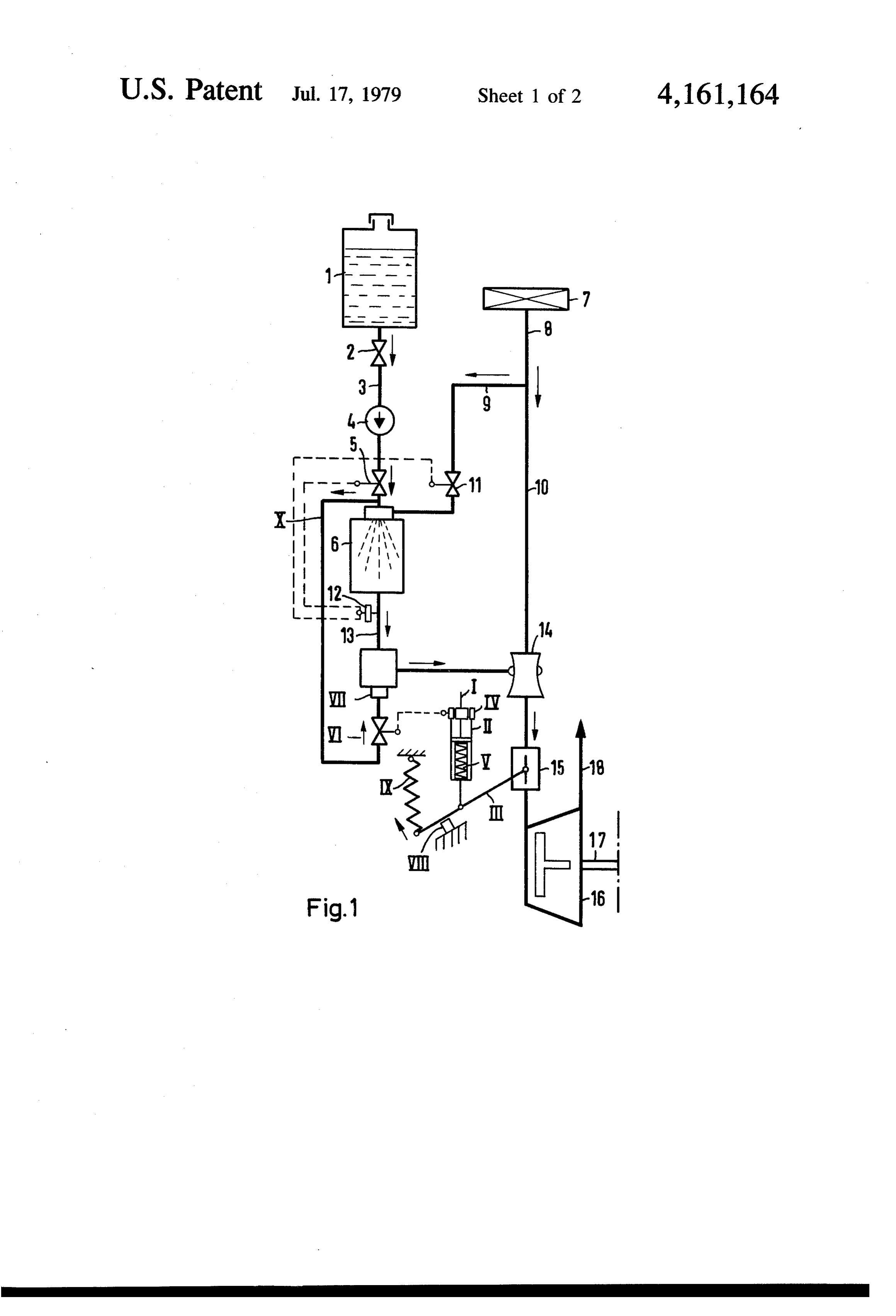
SUMMARY OF THE INVENTION The embodiment shown by FIG. 1 is relatively sim ple and inexpensive and may be used in the case of an
An object of the present invention is to provide for automotive vehicle engine, for example, of the type retaining the advantages described above while permit normally using a standard carburettor and intake mani ting the development of the full or substantially full fold. In this FIG. 1, the liquid fuel in the supply tank 1 rated power of the engine. feeds through what may be a manually operated fuel This object is attained above all by an improvement cock 2, via a fuel line 3 to a fuel pump 4 which intro wherein, generally speaking, means including a control duces it at a pressure sufficient for good atomising valve, are provided for mixing liquid (hydrocarbon) through a fuel metering valve 5 of the remote-con fuel of the hydrocarbon or higher alcohol type with the 65 trolled type, into the converter 6 of the type previously gaseous fuel supplied by the converter to the engine, to described. For the partial combustion of the liquid fuel provide the latter with an enriched fuel gas, when re in the converter 6 where it is introduced as in atomized quired. This control valve for the liquid fuel is con form, air sucked in through an air cleaner 7, is fed into
Page 5
the converter 6 via a line 8 and branch line 9, the line 8 giving transducer IV and its lower end a spring V with in this instance being a part of the engine's air intake line the lever III of the throttle valve 15. In the shown 10. The amount of air required for the partial combus position, the accelerator pedal is fully depressed and, tion in the converter 6 is regulated by a remote control therefore, the transducer's movable solenoid is fully air metering valve 11 in the line 9 going to the con- 5 positioned within the induction coil and thus producing verter. The converter contains a catalyst and/or other a signal transmitted, as indicated by broken lines, to a known means for a relatively very low gasification remote-controlled metering valve VI introducing the temperature which at elevated temperatures converts highest possible amount of the liquid fuel via an injec the liquid fuel to the gaseous fuel. tion device VII to the gaseous fuel leaving the con In what may be a prior art manner, the temperature of 10 verter 6 via the line 13 which goes to the device VII. the output of the converter 6 is sensed by a temperature Thus, a maximum enrichment of the gaseous fuel and sensor 12 linked or connected, as indicated by the bro therewith a maximum output of the engine is provided. ken lines, to the liquid flow metering valve 5 and the air The system is, for instance, designed so that the fuel flow metering valve 11, teh arrangement being such as metering valve VI only begins to open when the engine to keep a proper ration between the two fluids as re- 15 has reached its maximum output at using only gaseous quired for proper operation of the converter 6 during its fuel, i.e. when the intake throttle valve 15 of the engine varying outputs. The gaseous fuel output of the con 16 is fully opened. At this moment, the stop VIII for the verter 6 is sucked via the line 13, by an aspirator 14 lever III is not yet reached and the accelerator pedal is powered by the flow of the intake air sucked through not fully depressed, i.e. also has not reached its not the intake pipe line 10 by the engine when the pressure 20 shown stop.
in its combustion chamber or chambers, during intake The amount of liquid fuel injected into the gaseous cycles, reduces to below atmospheric pressure. The fuel increases as the accelerator pedal is further de aspirator 14 maintains a pressure differential between pressed. As described above, the molecules of the in the branch line 9 supplying the converter 6 and the jected fuel preferably is cracked by the sensible heat of latter's output line 13, thus causing flow through the 25 the gaseous fuel, changing thereby to smaller molecules converter 6. of a relatively very low boiling point and - most im A throttle valve 15, such as is normally operated by a portant - of a high octane number. foot pedal or accelerator, controls the intake of the The intake throttle valve return spring is shown at IX internal combustion engine 16. The aspirator 14 func and its elasticity and that of the spring V should be tions not only to provide flow through the converter 6, 30 interrelated so that the sensor IV does not start to oper but also to mix the converter's gaseous flow output with ate until the engine 16 has reached its full power with the air drawn in through the intake line 10. As the throt the pure gaseous fuel. The valve VI is supplied with the tle valve 15 is opened, the air flow through the line 10 liquid fuel by way of a branch lineX branched off from to the engine increases, the aspirator 14 accelerates the the liquid fuel feed line 3 of the converter 6, and that flow through the converter 6 while the sensor 12 in this 35 after the main fuel metering valve was actuated by the case automatically controls the metering valves 5 and temperature sensor for the gaseous fuel at the convert 11 to increase the flow of the liquid fuel and air to the er's outlet. Thus, it can be seen that the liquid fuel sup- - converter in, of course, the proper proportions required plied for enrichment of the gaseous fuel, when de for the converter 6 to produce the gaseous fuel. manded, is the same as the liquid fuel fed to the con The converter 6 is miniaturized so it can be put into verter 6. This would ordinarily be a low-cost hydrocar the engine compartment of an automotive vehicle. The bon liquid of low-octane value, but its knocking or gaseous fuel leaves the converter 6 at an elevated tem preignition characteristic and its atmosphere pollution perature, thus - in consequence of an increased tem potentiality are diminished (1) by the fact that a major perature of the mixture of the intake air and said gaseous amount of the fuel supplied to the engine 16 is the out fuel, and in addition in consequence of the volume taken 45 put of the converter 6 even when the engine 16 is oper from the intake air by the gaseous fuel in said mixture ating under full-load conditions demanding a maximum the mass of the cylinder charge and therewith the maxi fuel enrichening and (2) by the above mentioned effect mum power output is reduced in comparison to that of cracking.
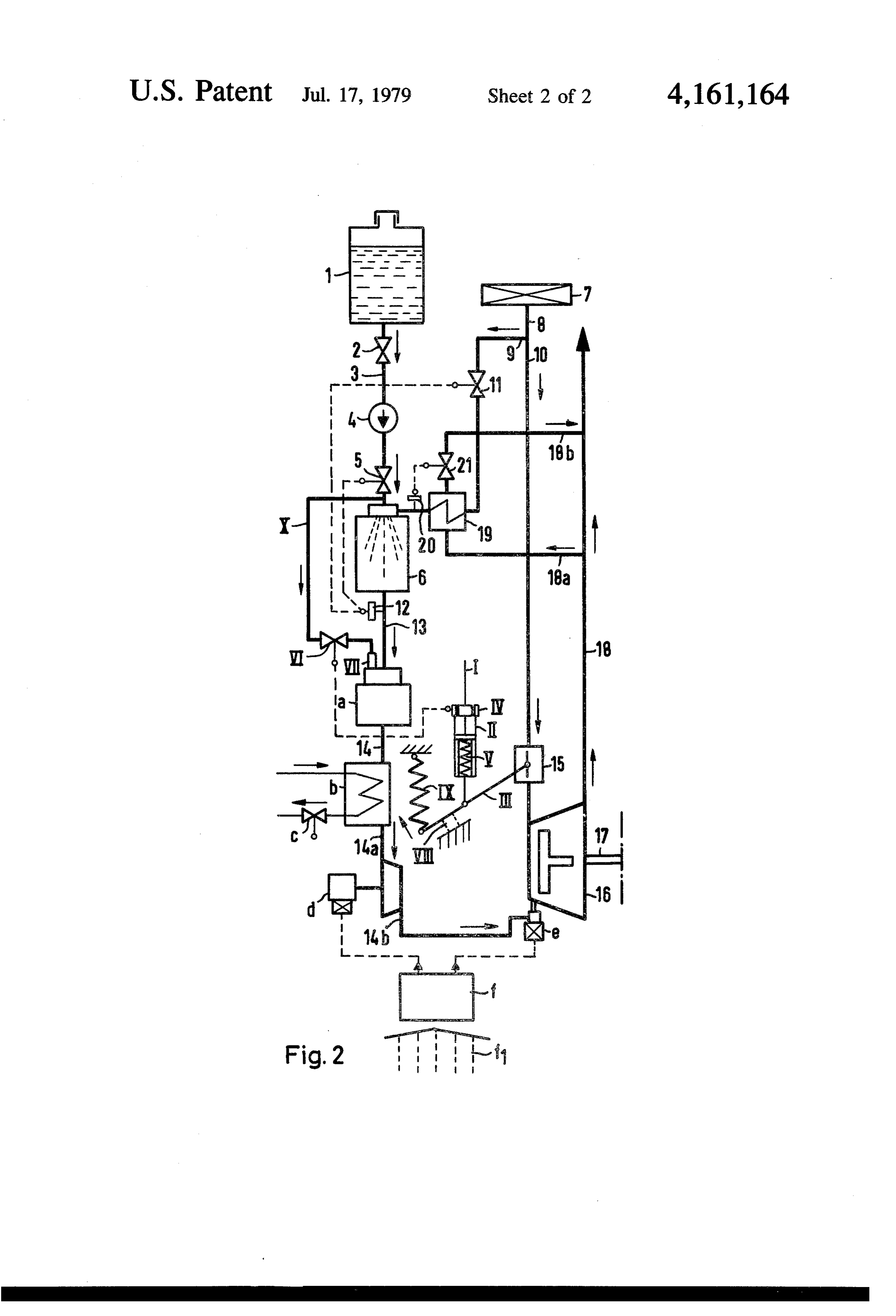
obtained when the engine is working in the conven Referring to FIG. 2 showing a more advantageous tional manner, i.e. with liquid fuel mixed into the intake 50 but also more complex embodiment of the invention as air by means of a carburettor or an injection device. A used for a fuel injection engine, where for components further reduction of the output and in addition an in corresponding to those shown by FIG. 1 the same nu creasing fuel consumption is existent because the heat merals are used.
created by the partial oxidation of the liquid fuel in the The difference in this case is that the output of the converter for the purpose of its gasifying is thermody 55 converter 6 and the enrichening liquid fuel are fed to namically lost for the engine. This has the consequence gether to a cracking reactora, where - eventually with of a corresponding lower caloric value per mass unit of the aid of a suitable catalyst - the liquid fuel may be the air/gaseous fuel-mixture than that of the air/liquid converted partially or wholly to a crack gas. Another fuel-mixture used in above mentioned conventional difference is that the fuel gas-mixture leaving the reac engine. However, under normal driving conditions, the 60 tor a goes through a heat exchanger b provided with a engine 16 is provided with an adequate charge of gase coolant under the control of a valve c, abstracting some ous fuel and air. of the heat from the air/fuel gas-mixture and increasing As it is illustrated in FIG. 1, the engine's intake throt its density, respectively decreasing its specific volume tle valve 15 is fully opened by its actuating rod I, which and thereby increasing the charge and output of the on the one hand is connected with the not shown accel 65 engine, the cooled fluid via a compressord, being com erator pedal actuated by the driver, and on the other pressed or pressurized so that it can be injected via an hand is connected via an elastic connection member II, injection valve e to the motor 16, the latter being of the containing at its upper end the accelerator's position electronic fuel-injection type as previously noted,
Page 6
which is characterized by controlling the opening time prising the step of admixing, by means of said second of the injection valve as a function of the engine's condi fuel metering valve, liquid hydrocarbon fuel from said tion in respect to load and speed and the conditions of fuel supply tank with said gaseous fuel produced by said the atmosphere and the temperature level of the engine. converter, subsequent to said step of converting and For reasons of a particularly intensive exhaust decon prior to said steps of supplying said gaseous fuel to said tamination it should be provided a leaning out of the engine and supplying said combustion air to said engine, mixture of gaseous fuel and engine's combustion air, as said step of admixing further comprising admixing said far as possible, in respect of maximum output, fuel con liquid hydrocarbon fuel with said gaseous fuel by open sumption and driveability. ing said second fuel metering valve to admix said liquid In this instance, the compressor functions to effect 10 hydrocarbon fuel with said gaseous fuel when said the flow through the converter 6 and the cracking reac throttle valve is fully opened.
tor a by suction, as well as to apply the necessary pres 2. The method recited in claim 1, wherein said engine sure for injection direction into the engine after its inlet further comprises an aspirator coupled to said throttle valve is closed. This pressure may be kept constant. If valve, said gas intake line, and to said injection device the compressor d is powered by an electric motor, by 15 for supplying combustion air to said engine to support means of a prior art electronic control system fin which combustion of said gaseous fuel produced by said con the desired pressure is entered as information in the verter, wherein said oxygen-containing gas comprises form of a control quantity f. This would be analogous air, and wherein said method further comprises the step to the control used by a liquid gasoline engine using of mixing said combustion air with said gaseous fuel electronic fuel injectors. 20 subsequent to said step of admixing by means of said The heat required for gasifying the liquid fuel in the aspirator, thereby supplying a mixture of said gaseous converter 6 requires quasi combustion of some of the fuel and combustion air to said engine through said liquid fuel and the amount of this fuel so required is lost throttle valve.
insofar as engine output and fuel consumption, too, is 3. The method recited in claim 1, wherein said engine concerned. To reduce this loss, the engine's exhaust 25 further comprises a cracking reactor coupled to said pipe 18 has a branch line leaving the pipe at 18a and injection device and to said converter, and wherein said returning at 18b, which goes through aheat exchanger 19 method further comprises the step of adjusting the tem through which the air intake to the converteris passed for perature and flow velocity of said gaseous fuel and the preheating, thus reducing the amount of liquid fuel flow velocity of said liquid hydrocarbon fuel so that required to be burned for the gasifying reactions to be 30 said liquid hydrocarbon fuel is completely cracked, effective. A temperature sensor 20, using a prior art without the formation of soot, into a lower-molecular system indicated by broken lines, renders a valve 21 fuel in said cracking reactor.
responsive to the temperature of the preheated air fed to 4. The method recited in claim 3, wherein said engine the converter, this valve 21 controlling the exhaust flow further comprises a first heat exchanger coupled to said rate through the heat exchanger 19. 35 cracking reactor, and wherein said method further com What is claimed is: prises the step of cooling said gaseous fuel produced by 1. In a method of operating an internal combustion said converter in said heat exchanger subsequent to said engine, said engine including a fuel supply tank for step of admixing.
receiving a liquid hydrocarbon fuel, a fuel line coupled 5. The method recited in claim 4, wherein said engine to said fuel supply tank, a gas intake line, a throttle further comprises a compressor coupled to said heat valve coupled to said engine and to said gas intake line, exchanger and an injection valve coupled to said com a converter for converting said liquid hydrocarbon fuel pressor, and wherein said method further comprises the to a soot-free gaseous fuel by means of partial combus step of producing pressure on said gaseous fuel pro tion, a first branch line coupled to said gas intake line, a duced by said converter subsequent to said steps of gas metering valve coupled to said first branch line and 45 admixing and cooling by means of said compressor and to said converter, a first fuel metering valve coupled to injecting said gaseous fuel into said engine by means of said fuel line and said converter, an injection device said injection valve subsequent to said step of producing coupled to said converter, a second branch line coupled pressure.
to said fuel line between said fuel metering valve and 6. The method recited in claim 5, wherein said engine said converter, and a second fuel metering valve cou 50 further comprises an exhaust pipe, third and fourth pled to said second branch line and to said injection branch lines coupled to said exhaust pipe, and a second device, said method including the steps of converting heat exchanger coupled to said gas metering valve and said liquid hydrocarbon fuel to a soot-free gaseous fuel to said converter and to said third and fourth branch by means of partial combustion in said converter while lines and wherein said method further comprises the supplying an oxygen-containing gas to said converter 55 step of heating said oxygen-containing gas supplied to by means of said first branch line and said gas metering said converter in said second heat exchanger by means valve, supplying said gaseous fuel to said engine, and of exhaust gases produced by said engine flowing supplying combustion air to said engine by means of through said third and fourth branch lines and said said throttle valve and said gas intake line to support second heat exchanger.
combustion of said gaseous fuel, the improvement com- 60 k k k E
Provenance
- Collection
- Cited prior art
- Original PDF
- patentimages.storage.googleapis.com →
- Filed
- 1975-05-30
- Pages
- 6
- Method
- pdftotext (the PDF's own text layer) + pdftoppm 300dpi page scans
- Source
- Google Patents bibliographic record
- Granted
- 1979-07-17
- Inventors
- Erhard Muhlberg; Siemens AG
- Transcribed from
- patentimages.storage.googleapis.com →