patent · US5070431
Display board illuminating device for passive displays
3 December 1991
Page 1 — bibliographic record
United States Patent (19) 11 Patent Number: 5,070,431 Kitazawa et al. (45. Date of Patent: Dec. 3, 1991 (54) DISPLAYBOARD ILLUMINATING DEVICE 4,453,220 6/1984 Trcka et al. ........................... 362/29 FOR PASSIVE DISPLAYS 4,630,895 12/1986 Abdala, Jr. et al. ... 362/31 4,874,228 10/1989 Aho et al. ........... ... 362/26 (75 Inventors: Hideki Kitazawa; Ryohei Terada; 4,890,201 12/1989 Toft ................ ... 362/31 Shogo Takeuchi; Tsutomu Kayama; 4,903, 171 2/1990 Livezey et al. . ... 362/26 Kohichi Tanimoto; Nobuo Utsugi; 4,929,062 5/1990 Guzik et al. .... ... 362/31 Yoshiaki Nagai, all of Kawagoe, 4,933,814 6/1990 Sanai ..................................... 362/26 Japan FOREIGN PATENT DOCUMENTS (73) Assignee: Pioneer Electronic Corporation, 952388 3/1964 United Kingdom .................. 362/31 Tokyo, Japan
Primary Examiner-Ira S. Lazarus 21 Appl. No.: 559,358 Assistant Examiner-Y. Quach 22 Filed: Jul. 30, 1990 Attorney, Agent, or Firm-Perman & Green 30 Foreign Application Priority Data (57) ABSTRACT Aug. 3, 1989 JP Japan .................................. 1-202560 A display board illuminating device includes a light guide plate arranged to face the back of a display board 51) Int. Cl. .............................................. F21V 13/00 and a light source disposed to face the side end of the 52 U.S. Cl. ........................................ 362/31; 362/26; light guide plate. The side end of the light guide plate is 362/27; 362/30; 362/800 inclined toward the center of the light guide plate in the 58 Field of Search ....................... 362/24, 26, 29, 30, direction of the display board. By this configuration an
angle of an optical axis refracted at the surface of the 56) References Cited side end and incident into the light guide plate with
2,712,593 7/1955 Merchant .............................. 362/27 the whole area of the display board is illuminated effi 3,56i, 145 2/1971 Shotwell ............................... 362/26 ciently.
4,257,084 3/1981 Reynolds .............................. 362/3 4,258,643 3/1981 Ishikawa ............................... 362/26 10 Claims, 10 Drawing Sheets
NZZZZZZZZZZZZZZZZZZZZZZZY
YZZZZZY/ZvZazMat Zoe ZZZZZZ,12ZZZZZZZZZZZZYZZZZY
s See Nati
Page 2
Drawing sheet — no readable text.
Page 3
Drawing sheet — no readable text.
Page 4
Drawing sheet — no readable text.
Page 5
Drawing sheet — no readable text.
Page 6
Drawing sheet — no readable text.
Page 7
Drawing sheet — no readable text.
Page 8
Drawing sheet — no readable text.
Page 9
Drawing sheet — no readable text.
Page 10
Drawing sheet — no readable text.
Page 11
Drawing sheet — no readable text.
Page 12
present invention and a display board to be illuminated
DISPLAYBOARD ILLUMINATING DEVICE FOR by the illuminating device;
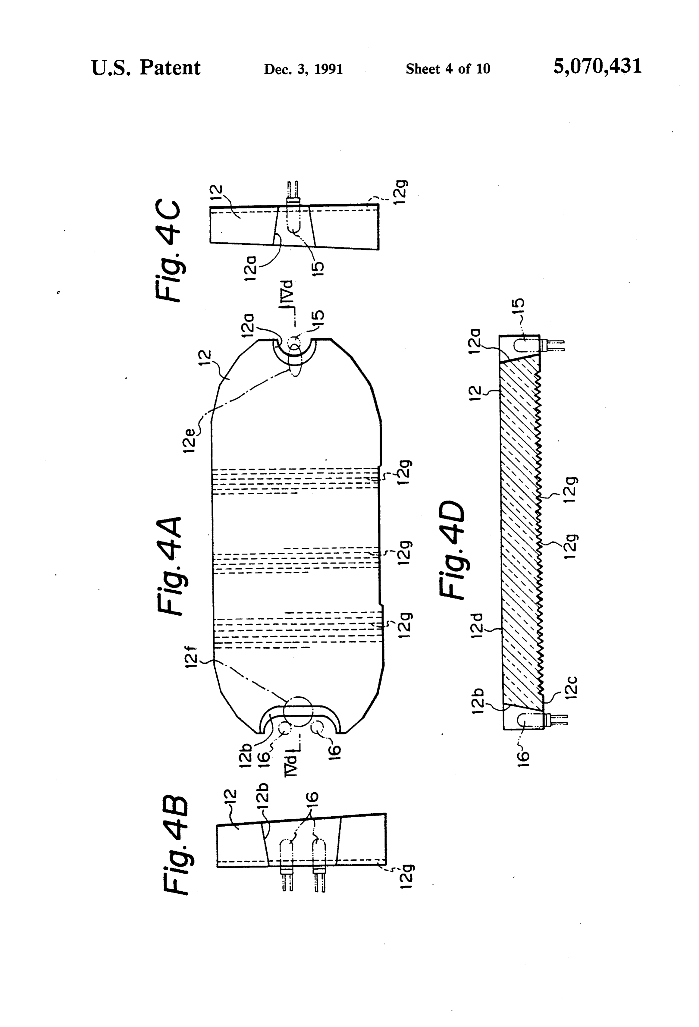
PASSIVE DISPLAYS FIGS. 4A through 4C are front, left side, and right side views of the light guide plate included in the dis
BACKGROUND OF THE INVENTION 5 play board illuminating device shown in FIG. 2; 1. Field of the Invention FIG. 4D is a sectional view taken along a line IV d-IVd of FIG. 4A;
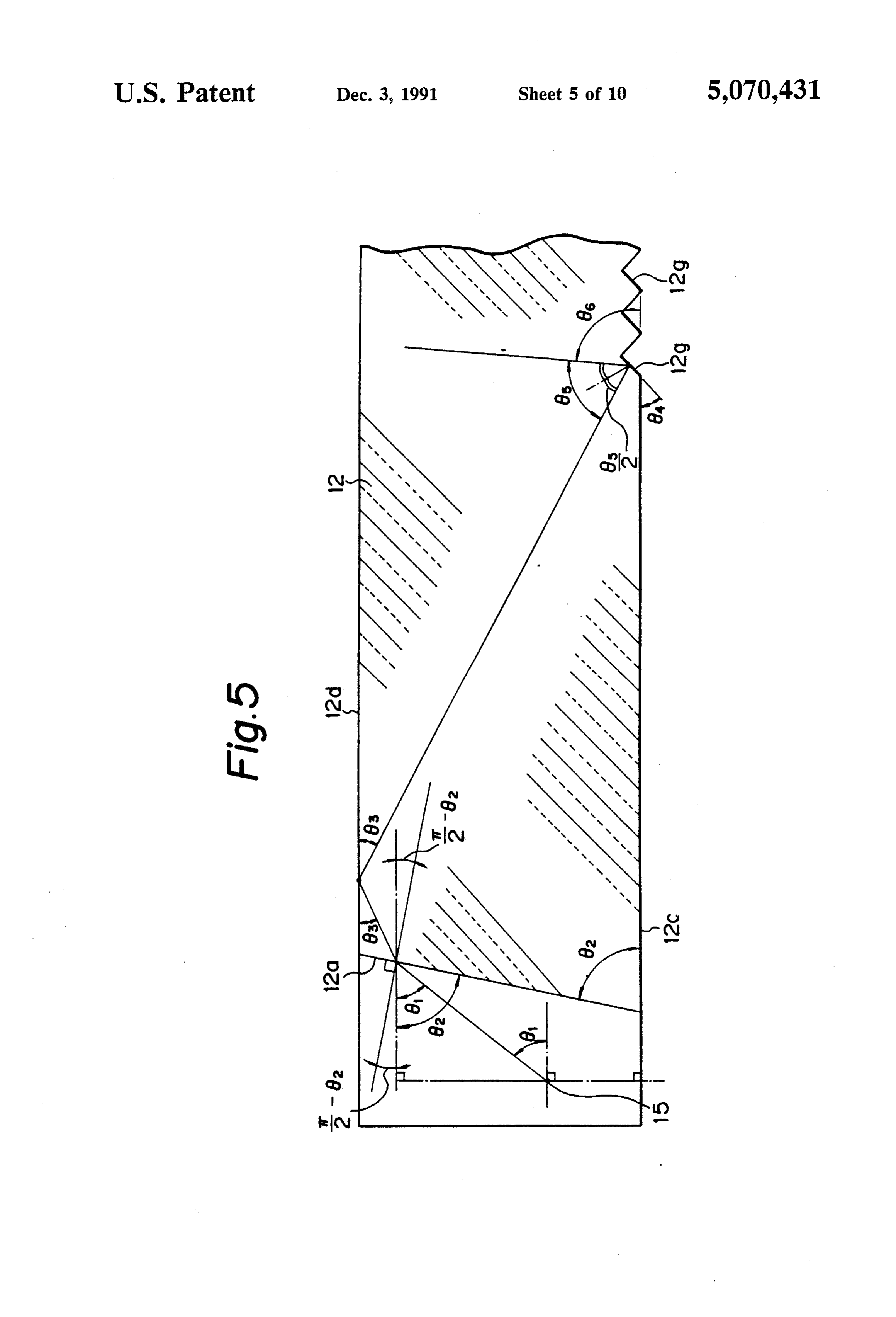
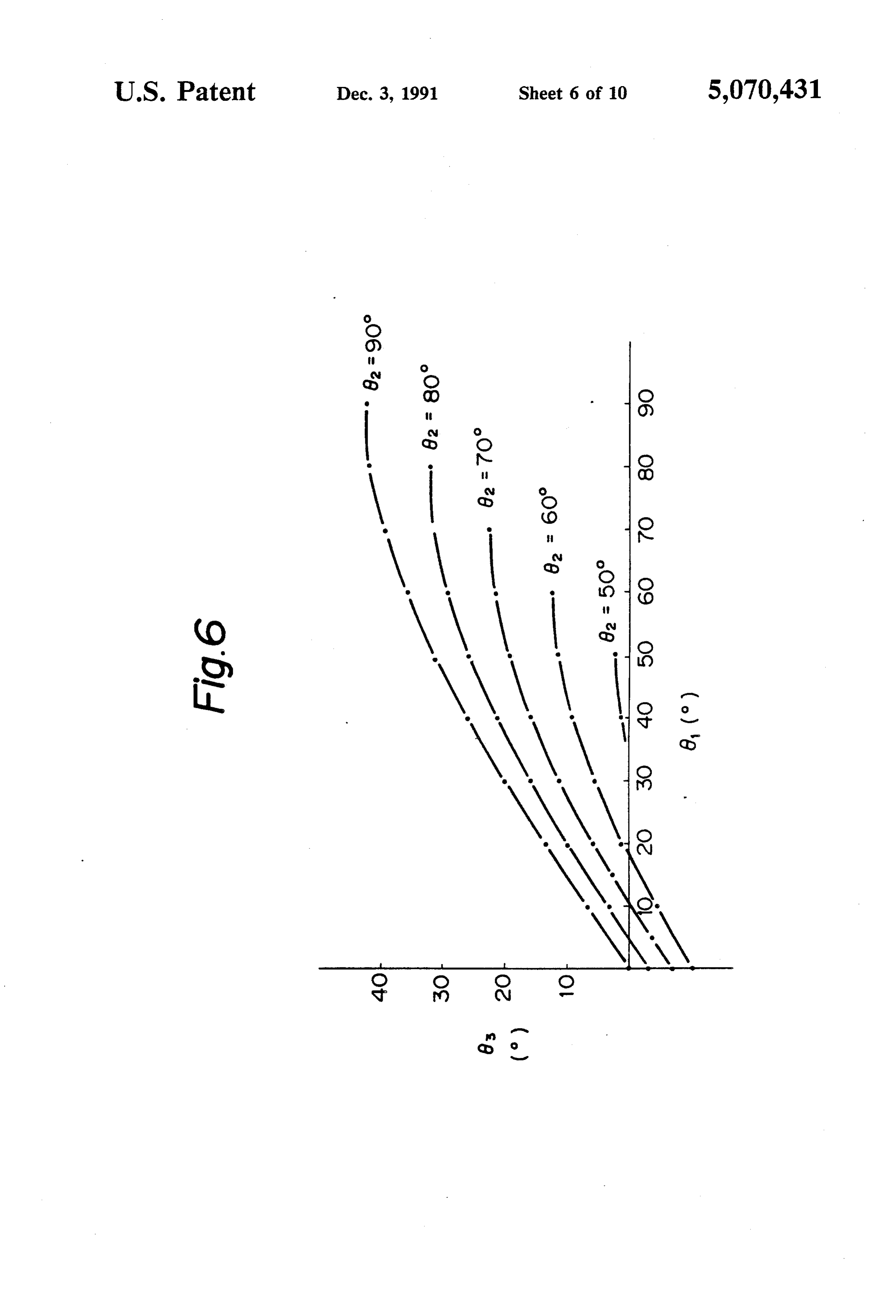
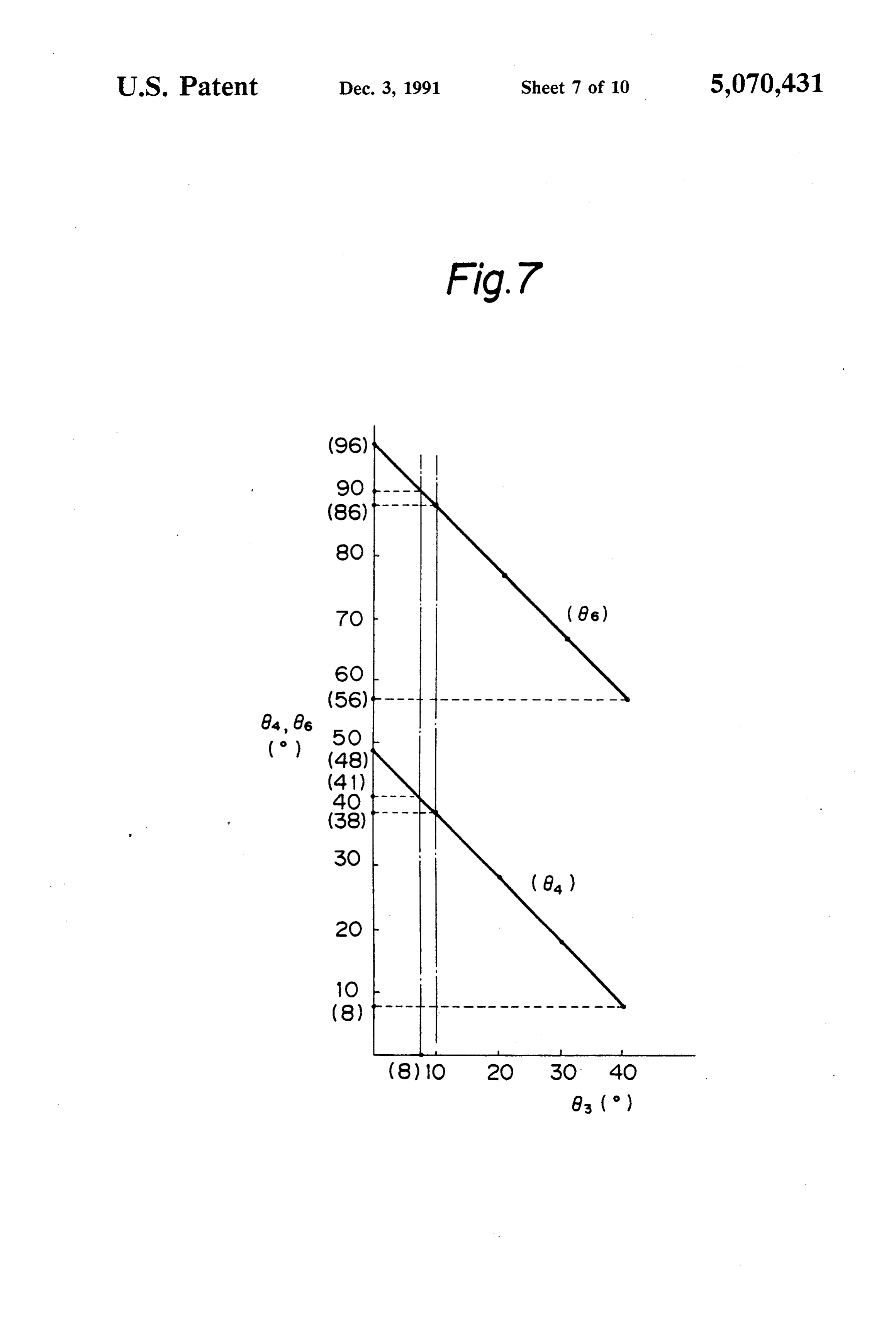
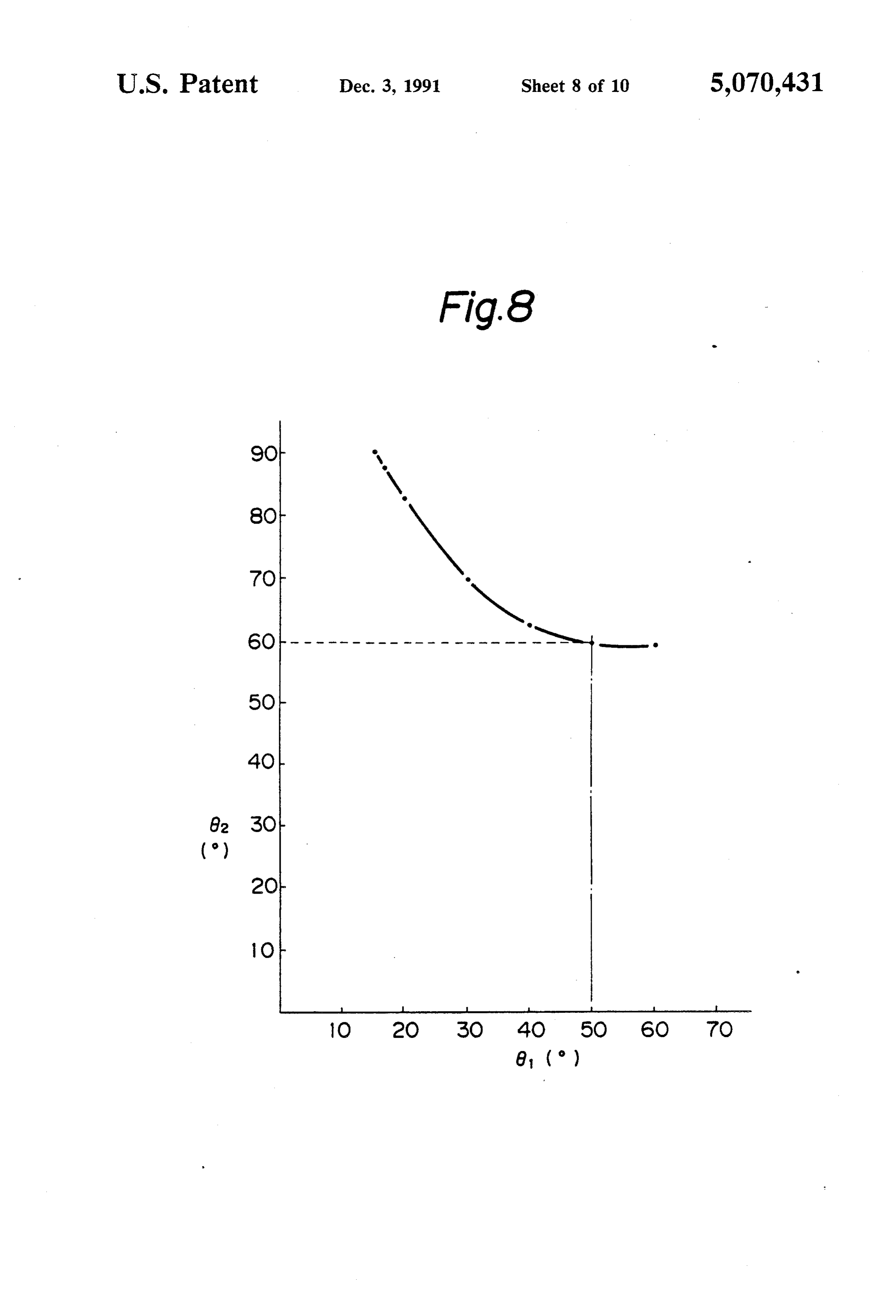
The present invention relates to a display board illu FIG. 5 is an enlarged view of a portion A in FIG. 3; minating device for a display unit including a display FIGS. 6through 8 are graphs for explaining the func board, such as a dial scale of a tuner or a dial plate. 10 tion of the display board illuminating device shown in 2. Description of Background Information FIGS. 2 through 5;
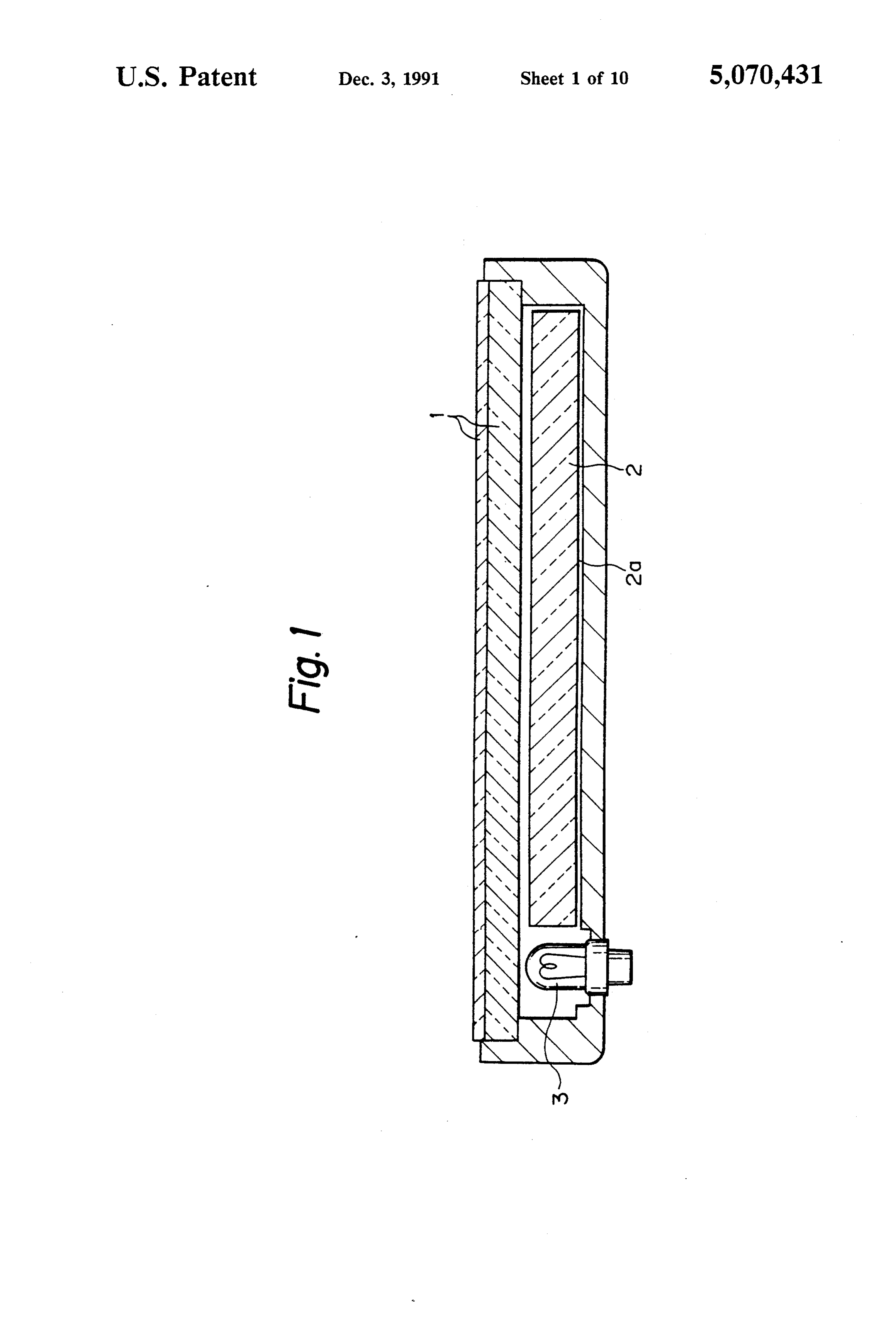
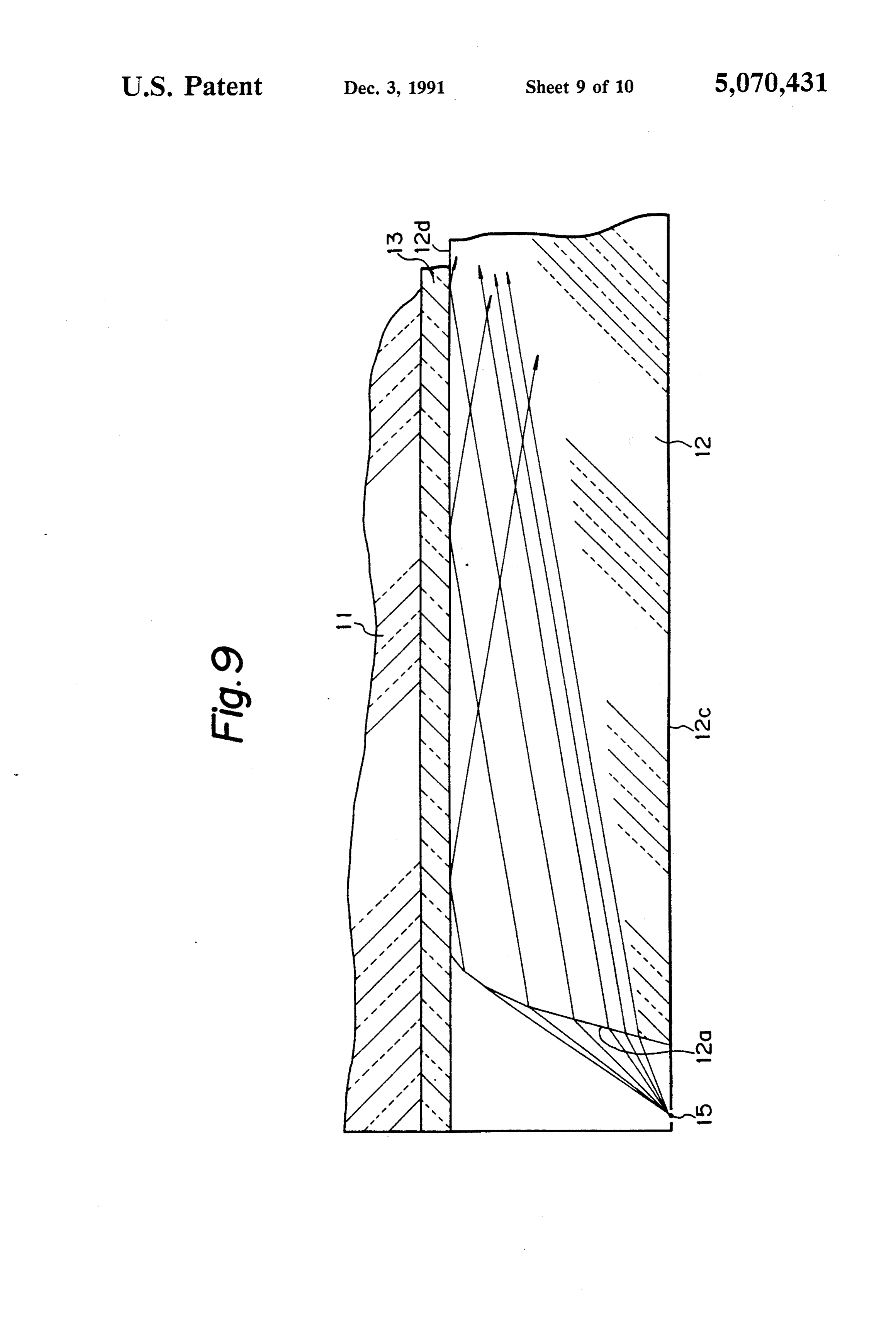
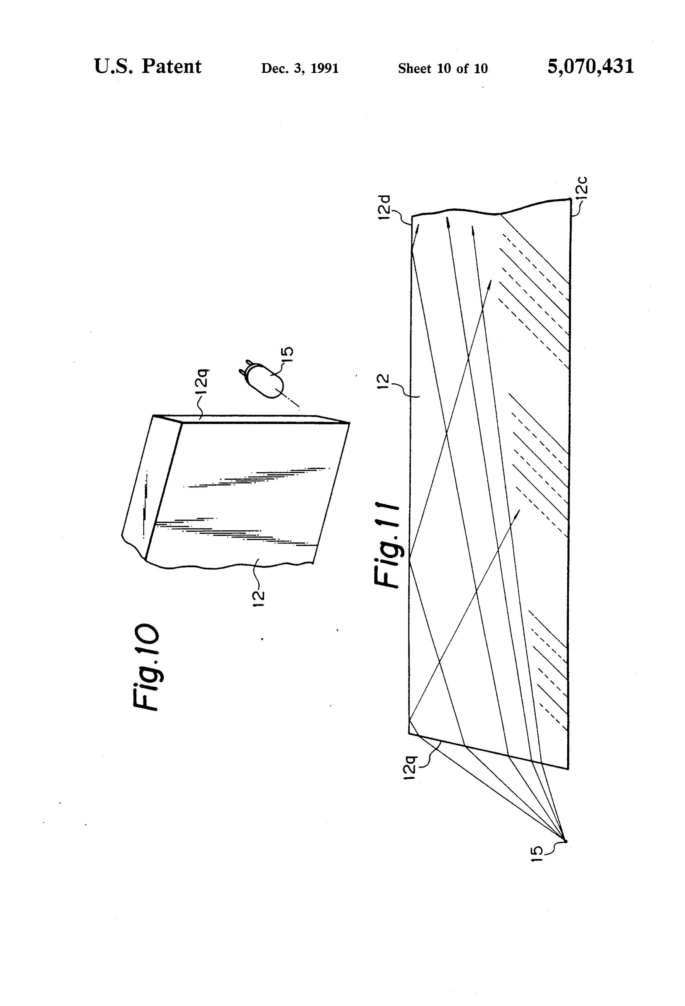
FIG. 1 shows an example of conyentional devices for FIG. 9 is a longitudinal sectional view of a major part illuminating a display board. As shown, this conven of a display board illuminating device as a second em tional device includes a light guide plate 2 placed to face bodiment of the invention; and the back of an elongated rectangular display board 1 15 FIGS. 10 and 11 are perspective and longitudinal and a light emitting element 3, functioning as a light sectional views respectively, of a main part of a display source, disposed to face an end surface of the light guide board illuminating device as a third embodiment of the plate 2 at one side in the longitudinal direction of the invention.
light guide plate 2. The back surface 2a of the light guide plate 2 is formed into a rough surface or covered 20 DETAILED DESCRIPTION EMBODIMENTS
OF PREFERRED
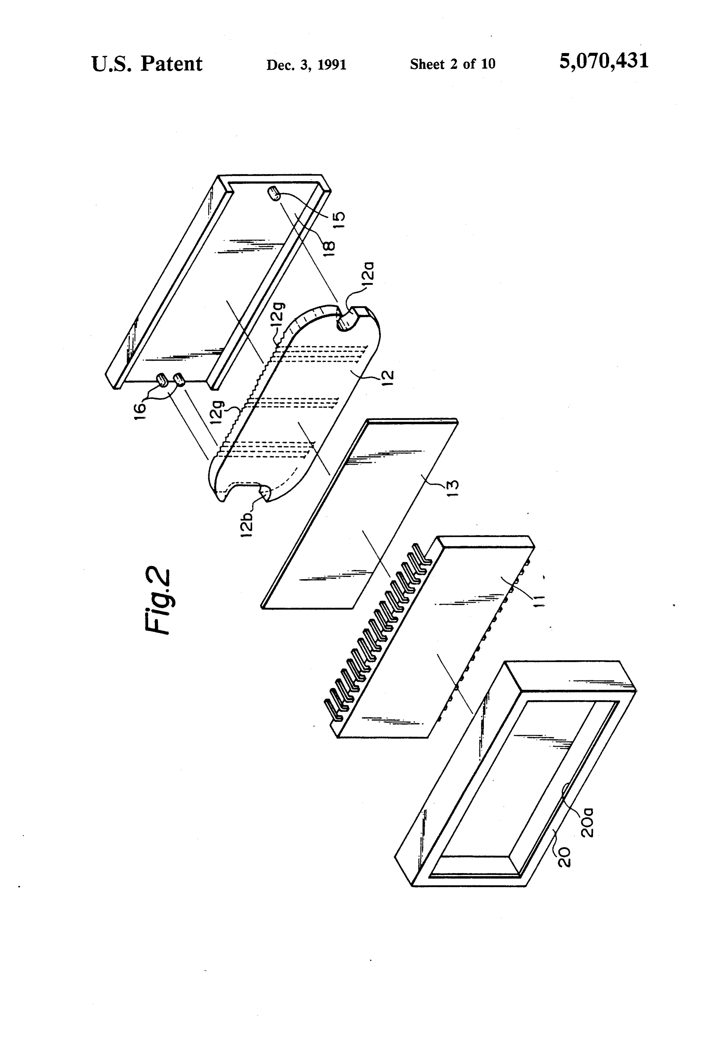
with a white printing material in order to diffuse the light. The preferred embodiments of the present invention In the illuminating device having the construction will be described with reference to FIGS. 2 through of described above, the light emitted from the light emit the accompanying drawings.
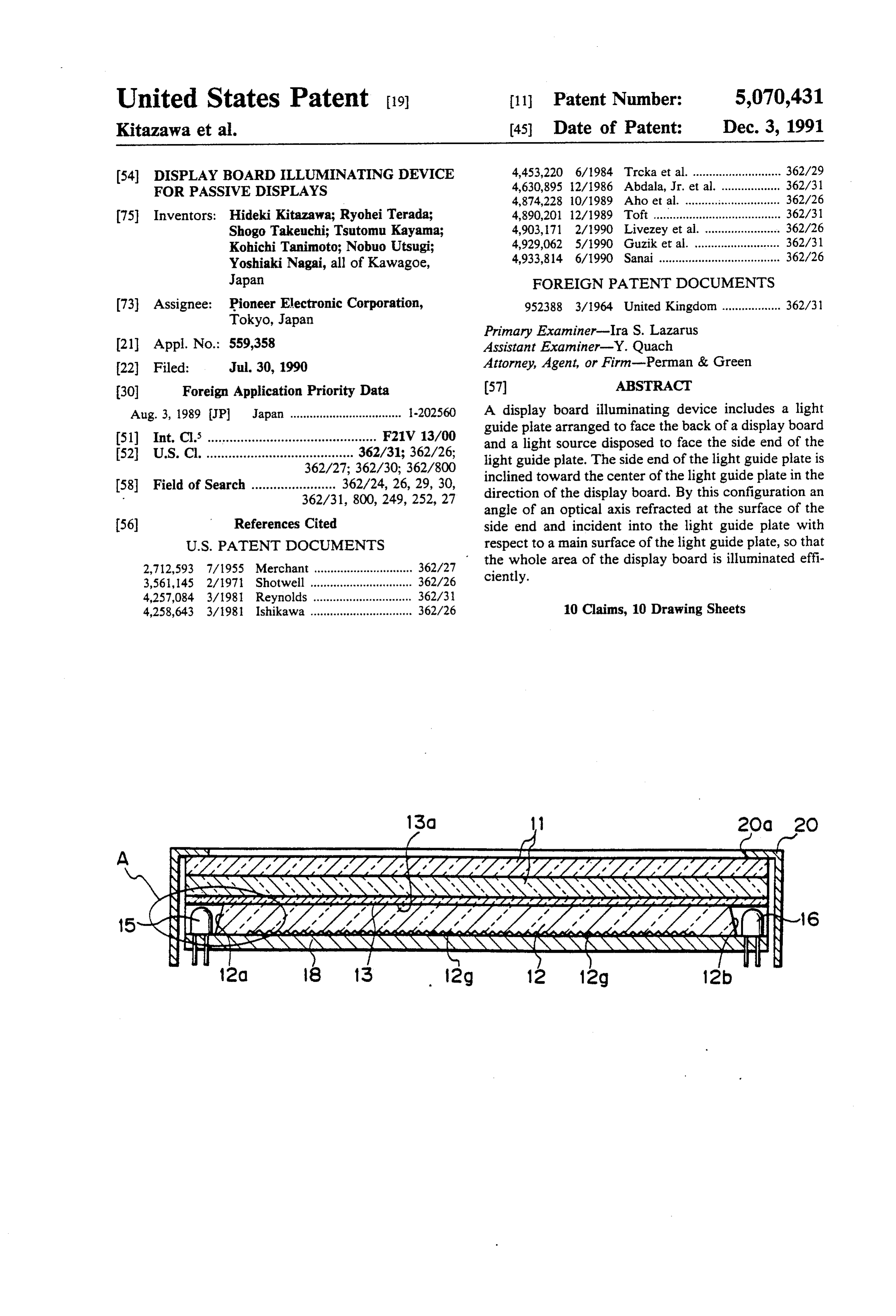
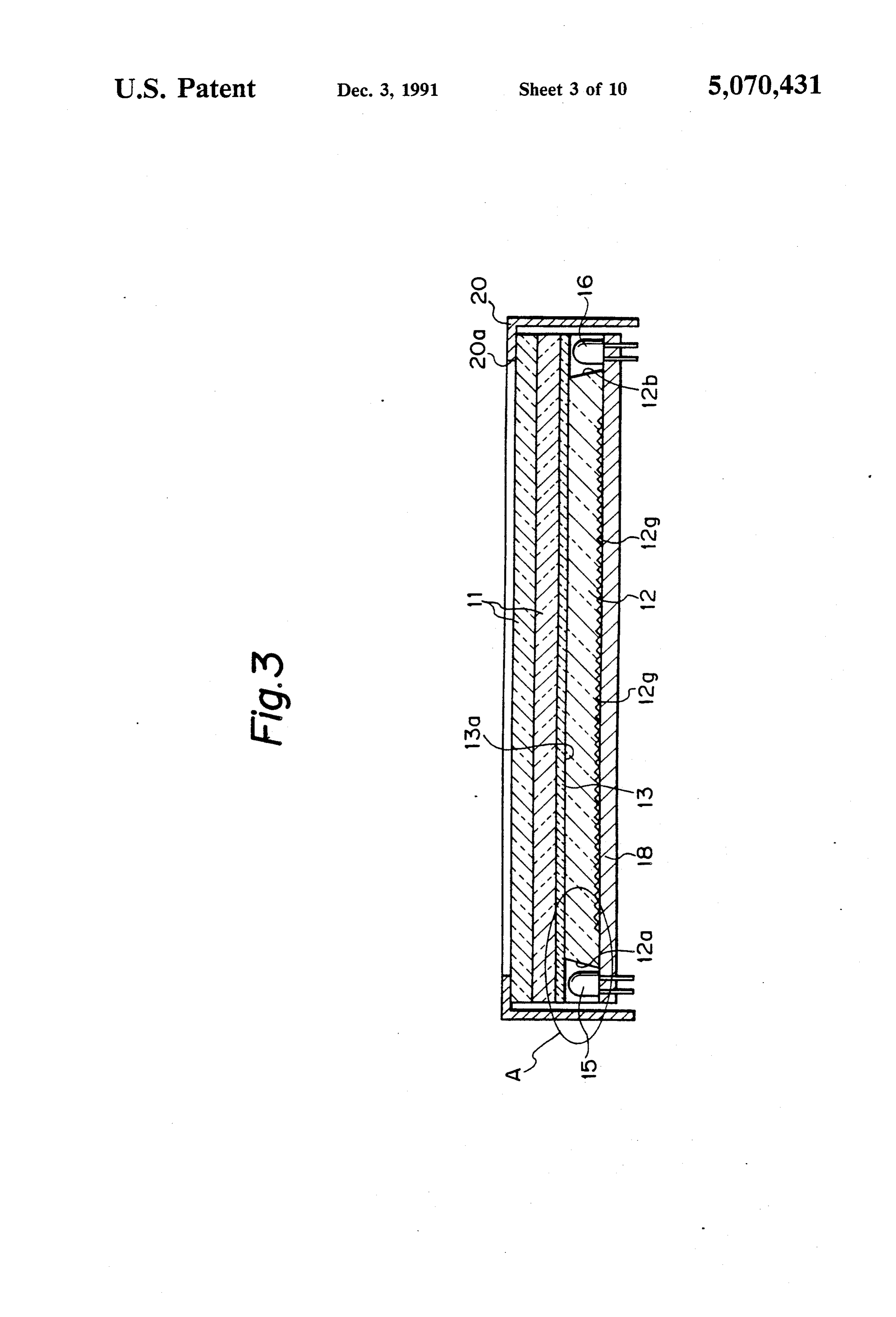
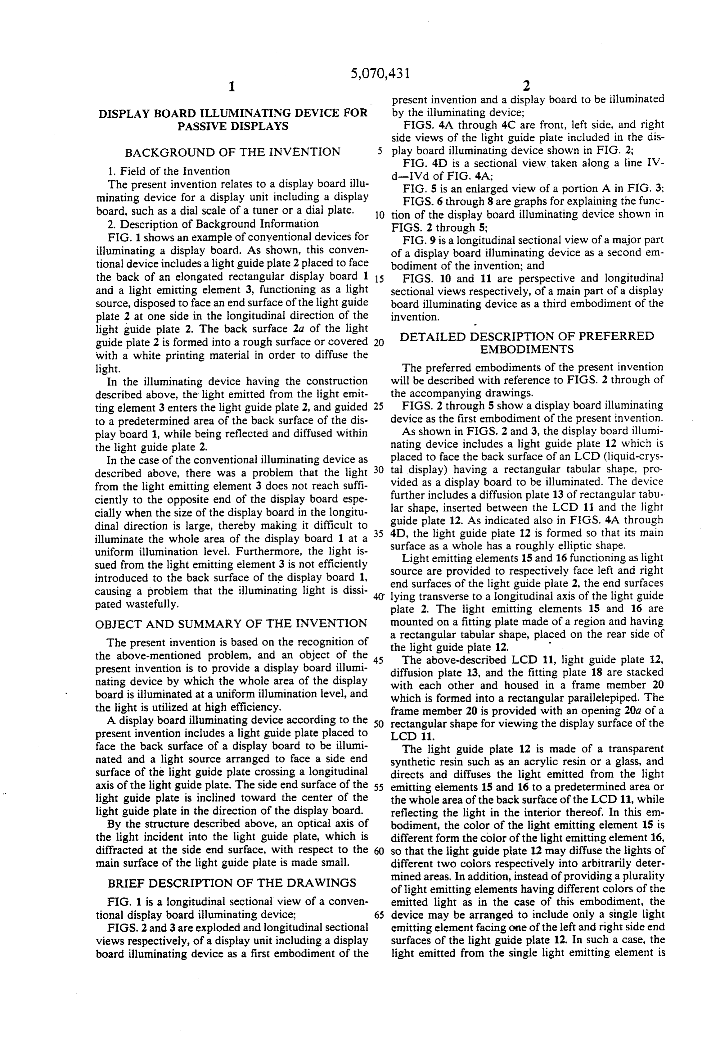
ting element 3 enters the light guide plate 2, and guided 25 FIGS. 2 through 5 show a display board illuminating to a predetermined area of the back surface of the dis device as the first embodiment of the present invention. play board 1, while being reflected and diffused within As shown in FIGS. 2 and 3, the display board illumi the light guide plate 2. nating device includes a light guide plate 12 which is In the case of the conventional illuminating device as placed to face the back surface of an LCD (liquid-crys described above, there was a problem that the light 30 tal display) having a rectangular tabular shape, pro from the light emitting element 3 does not reach suffi vided as a display board to be illuminated. The device ciently to the opposite end of the display board espe further includes a diffusion plate 13 of rectangular tabu cially when the size of the display board in the longitu lar shape, inserted between the LCD 11 and the light dinal direction is large, thereby making it difficult to 35 guide
plate 12. As indicated also in FIGS. 4A through the light guide plate 12 is formed so that its main illuminate the whole area of the display board 1 at a uniform illumination level. Furthermore, the light is surface as a whole has a roughly elliptic shape. Light emitting elements 15 and 16 functioning as light sued from the light emitting element 3 is not efficiently source are provided to respectively face left and right introduced to the back surface of the display board 1, end surfaces of the light guide plate 2, the end surfaces causing a problem that the illuminating light is dissi lying transverse to a longitudinal axis of the light guide pated wastefully. plate 2. The light emitting elements 15 and 16 are OBJECT AND SUMMARY OF THE INVENTION mounted on a fitting plate made of a region and having The present invention is based on the recognition of therectangular a tabular shape, placed on the rear side of light guide plate 12.
the above-mentioned problem, and an object of the 45 The above-described LCD 11, light guide plate 12, present invention is to provide a display board illumi diffusion plate 13, and the fitting plate 18 are stacked nating device by which the whole area of the display with each other and housed in a frame member 20 board is illuminated at a uniform illumination level, and which is formed into a rectangular parallelepiped. The the light is utilized at high efficiency. frame member 20 is provided with an opening 20a of a A display board illuminating device according to the 50 rectangular shape for viewing the display surface of the present invention includes a light guide plate placed to LCD 11.
face the back surface of a display board to be illumi The light guide plate 12 is made of a transparent nated and a light source arranged to face a side end synthetic resin such as an acrylic resin or a glass, and surface of the light guide plate crossing a longitudinal directs and diffuses the light emitted from the light axis of the light guide plate. The side end surface of the 55 emitting elements 15 and 16 to a predetermined area or light guide plate is inclined toward the center of the the whole area of the back surface of the LCD 11, while light guide plate in the direction of the display board. reflecting the light in the interior thereof. In this em By the structure described above, an optical axis of bodiment, the color of the light emitting element 15 is the light incident into the light guide plate, which is different form the color of the light emitting element 16, diffracted at the side end surface, with respect to the 60 so that the light guide plate 12 may diffuse the lights of main surface of the light guide plate is made small. different two colors respectively into arbitrarily deter BRIEF DESCRIPTION OF THE DRAWINGS mined areas. In addition, instead of providing a plurality of light emitting elements having different colors of the
FIG. 1 is a longitudinal sectional view of a conven emitted light as in the case of this embodiment, the tional display board illuminating device; 65 device may be arranged to include only a single light FIGS. 2 and 3 are exploded and longitudinal sectional emitting element facing one of the left and right side end views respectively, of a display unit including a display surfaces of the light guide plate 12. In such a case, the board illuminating device as a first embodiment of the light emitted from the single light emitting element is
Page 13
effectively guided to the end surface of the other side of inner surface, with respect to a front surface 12d of the the light guide plate 12 while maintaining a uniform light guide plate 12. The back surface 12c and the front illumination level. by a function which will be described surface 12d of the light guide plate are parallel with later. each other.
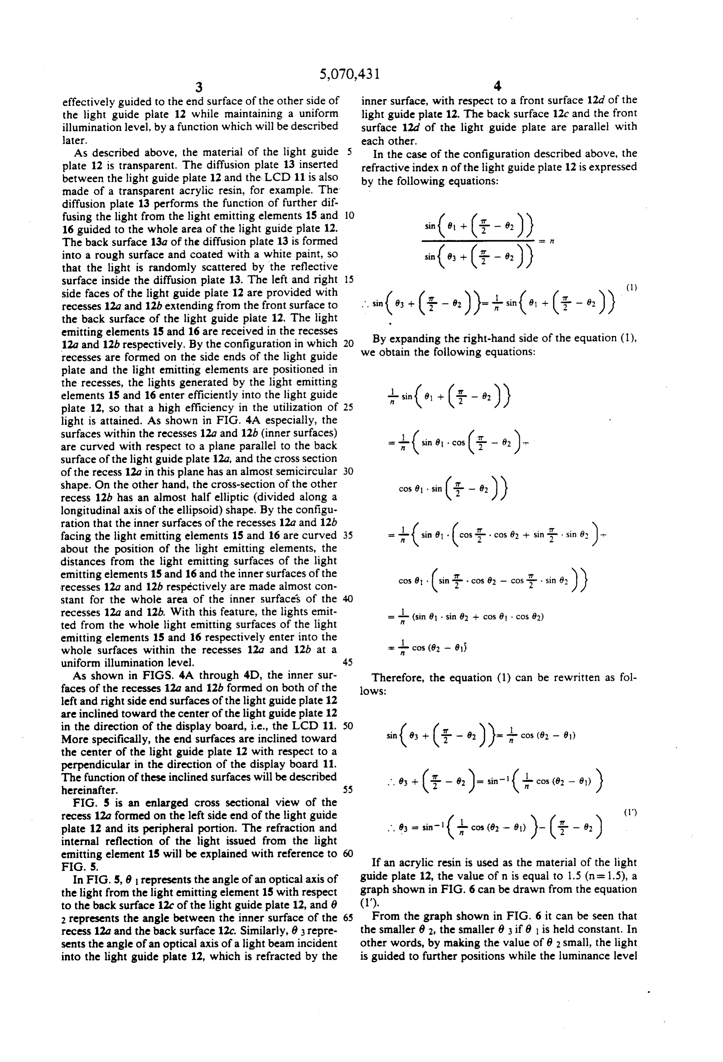
As described above, the material of the light guide 5 In the case of the configuration described above, the plate 12 is transparent. The diffusion plate 13 inserted refractive index n of the light guide plate 12 is expressed between the light guide plate 12 and the LCD 11 is also by the following equations:
made of a transparent acrylic resin, for example. The diffusion plate 13 performs the function of further dif fusing the light from the light emitting elements 15 and O 16 guided to the whole area of the light guide plate 12.
The back surface 13a of the diffusion plate 13 is formed into a rough surface and coated with a white paint, so that the light is randomly scattered by the reflective surface inside the diffusion plate 13. The left and right 15 side faces of the light guide plate 12 are provided with recesses 12a and 12b extending from the front surface to the back surface of the light guide plate 12. The light emitting elements 15 and 16 are received in the recesses 12a and 12b respectively. By the configuration in which 20 By expanding the right-hand side of the equation (l), recesses are formed on the side ends of the light guide we obtain the following equations: plate and the light emitting elements are positioned in the recesses, the lights generated by the light emitting elements 15 and 16 enter efficiently into the light guide +sin(e) -- (3-- 9.)) plate 12, so that a high efficiency in the utilization of 25 light is attained. As shown in FIG. 4A especially, the surfaces within the recesses 12a and 12b (inner surfaces) are curved with respect to a plane parallel to the back surface of the light guide plate 12a, and the cross section
of the recess 12a in this plane has an almost semicircular 30 shape. On the other hand, the cross-section of the other cos 8 sin (3- - e.) recess 12b has an almost half elliptic (divided along a longitudinal axis of the ellipsoid) shape. By the configu ration that the inner surfaces of the recesses 12a and 12b facing the light emitting elements 15 and 16 are curved 35 about the position of the light emitting elements, the - (in 8 (cost cos 8 + sin -. sine)-
distances from the light emitting surfaces of the light emitting elements 15 and 16 and the inner surfaces of the recesses 12a and 12b respectively are made almost con cos 8 . (in g . . cos 82 - cos r sines)) stant for the whole area of the inner surfaces of the recesses 12a and 12b. With this feature, the lights emit R (sin 81 . . sin 82 -- cos 0 , cos 82) ted from the whole light emitting surfaces of the light emitting elements 15 and 16 respectively enter into the whole surfaces within the recesses 12a and 12b at a cos (82 - 615
As shown in FIGS. 4A through 4D, the inner sur Therefore, the equation (1) can be rewritten as fol faces of the recesses 12a and 12b formed on both of the lows:
left and right side end surfaces of the light guide plate 12 are inclined toward the center of the light guide plate 12 in the direction of the display board, i.e., the LCD 11. 50
More specifically, the end surfaces are inclined toward the center of the light guide plate 12 with respect to a
perpendicular in the direction of the display board 11.
The function of these inclined surfaces will be described hereinafter.
FIG. 5 is an enlarged cross sectional view of the
recess 12a formed on the left side end of the light guide A. - tin-1 I- - -- plate 12 and its peripheral portion. The refraction and internal reflection of the light issued from the light
emitting element 15 will be explained with reference to 60
F.G. 5. If an acrylic resin is used as the material of the light In FIG. 5, 81 represents the angle of an optical axis of guide plate 12, the value of n is equal to 1.5 (n = 1.5), a the light from the light emitting element 15 with respect graph shown in FIG. 6 can be drawn from the equation to the back surface 12c of the light guide plate 12, and 0 (1").
2 represents the angle between the inner surface of the 65 From the graph shown in FIG. 6 it can be seen that recess 12a and the back surface 12c, Similarly, 83 repre the smaller 62, the smaller 83 if 8 is held constant. In sents the angle of an optical axis of a light beam incident other words, by making the value of 62 small, the light into the light guide plate 12, which is refracted by the is guided to further positions while the luminance level
Page 14
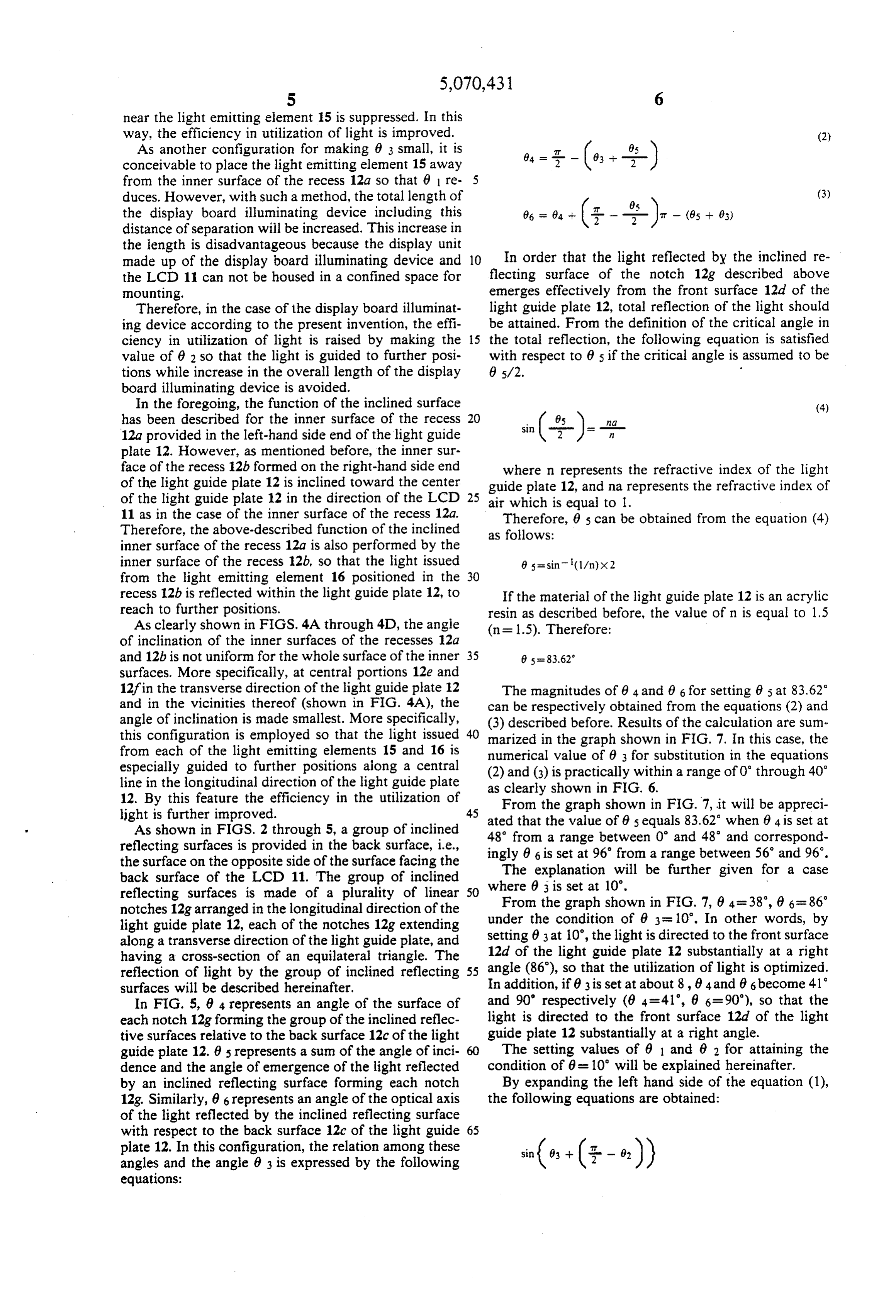
near the light emitting element 15 is suppressed. In this way, the efficiency in utilization of light is improved. (2) As another configuration for making 63 small, it is conceivable to place the light emitting element 15 away from the inner surface of the recess 12a so that 6 re 5 duces. However, with such a method, the total length of (3) the display board illuminating device including this 66 =
distance of separation will be increased. This increase in the length is disadvantageous because the display unit made up of the display board illuminating device and 10 In order that the light reflected by the inclined re the LCD 11 can not be housed in a confined space for flecting surface of the notch 12g described above mounting. emerges effectively from the front surface 12d of the Therefore, in the case of the display board illuminat light guide plate 12, total reflection of the light should ing device according to the present invention, the effi be attained. From the definition of the critical angle in ciency in utilization of light is raised by making the 15 the total reflection, the following equation is satisfied value of 62 so that the light is guided to further posi with respect to 65 if the critical angle is assumed to be tions while increase in the overall length of the display 85/2.
board illuminating device is avoided.
In the foregoing, the function of the inclined surface (4) has been described for the inner surface of the recess 20 12a provided in the left-hand side end of the light guide plate 12. However, as mentioned before, the inner sur face of the recess 12b formed on the right-hand side end where n represents the refractive index of the light of the light guide plate 12 is inclined toward the center guide plate 12, and na represents the refractive index of of the light guide plate 12 in the direction of the LCD 25 air which is equal to l.
11 as in the case of the inner surface of the recess 12a. Therefore, 0s can be obtained from the equation (4) Therefore, the above-described function of the inclined as follows:
inner surface of the recess 12a is also performed by the inner surface of the recess 12b, so that the light issued from the light emitting element 16 positioned in the 30 recess 12b is reflected within the light guide plate 12, to If the material of the light guide plate 12 is an acrylic reach to further positions. resin as described before, the value of n is equal to 1.5 As clearly shown in FIGS. 4A through 4D, the angle (n = 1.5). Therefore:
of inclination of the inner surfaces of the recesses 12a and 12b is not uniform for the whole surface of the inner 35 8 s = 83.62 surfaces. More specifically, at central portions 12e and 12f in the transverse direction of the light guide plate 12 The magnitudes of 64 and 6 6 for setting 65 at 83.62 and in the vicinities thereof (shown in FIG. 4A), the can be respectively obtained from the equations (2) and angle of inclination is made smallest. More specifically, (3) described before. Results of the calculation are sum this configuration is employed so that the light issued 40 marized in the graph shown in FIG. 7. In this case, the from each of the light emitting elements 15 and 16 is numerical value of 63 for substitution in the equations especially guided to further positions along a central line in the longitudinal direction of the light guide plate (2) and (3) is practically within a range of 0 through 40 as clearly shown in FIG. 6.
12. By this feature the efficiency in the utilization of From the graph shown in FIG.7, it will be appreci light is further improved. 45 ated that the value of 85 equals 83.62 when 04 is set at
As shown in FIGS. 2 through 5, a group of inclined 48 from a range between 0 and 48 and correspond reflecting surfaces is provided in the back surface, i.e., the surface on the opposite side of the surface facing the ingly 66 is set at 96 from a range between 56 and 96. The explanation will be further given for a case back surface of the LCD 11. The group of inclined where reflecting surfaces is made of a plurality of linear 50 From03theis graph set at 10.
notches 12g arranged in the longitudinal direction of the light guide plate 12, each of the notches 12g extending under the condition of 83 = 10. In other words, by along a transverse direction of the light guide plate, and setting 63 at i0, the light is directed to the front surface having a cross-section of an equilateral triangle. The 12d of the light guide plate 12 substantially at a right reflection of light by the group of inclined reflecting 55 angle (86), so that the utilization of light is optimized. surfaces will be described hereinafter. In addition, if 63 is set at about 8, 64 and 86 become 41 In FIG. 5, 84 represents an angle of the surface of and 90' respectively (0.4 = 41, 8 6=90), so that the each notch 12g forming the group of the inclined reflec light is directed to the front surface 12d of the light tive surfaces relative to the back surface 12c of the light guide plate 12 substantially at a right angle. guide plate 12. 85 represents a sum of the angle of inci The setting values of 6 1 and 0 2 for attaining the dence and the angle of emergence of the light reflected condition of 0 = 10' will be explained hereinafter. by an inclined reflecting surface forming each notch By expanding the left hand side of the equation (1), 12g. Similarly, 86 represents an angle of the optical axis the following equations are obtained: of the light reflected by the inclined reflecting surface with respect to the back surface 12c of the light guide 65 plate 12. In this configuration, the relation among these angles and the angle 8 3 is expressed by the following equations:
Page 15
-continued From the graph of FIG. 7, it will be appreciated that 62 should be set at 60 for setting 63 at 10, if 6 1 is equal
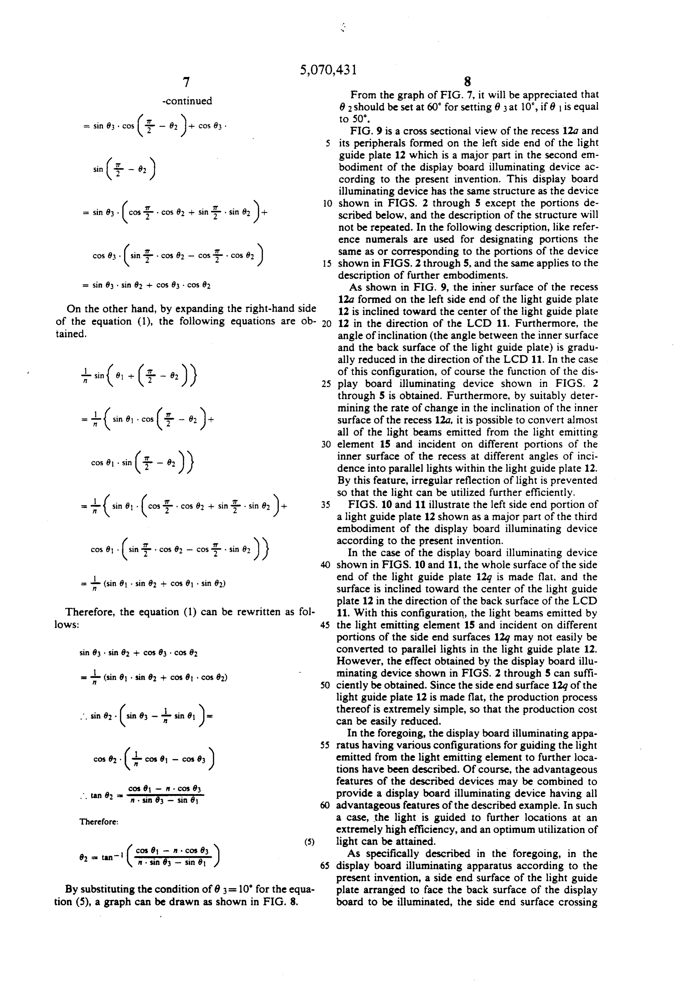
- in cos(- 8): cos 83 . FIG. 9 is a cross sectional view of the recess 12a and its peripherals formed on the left side end of the light guide plate 12 which is a major part in the second em bodiment of the display board illuminating device ac cording to the present invention. This display board illuminating device has the same structure as the device it O shown in FIGS. 2 through 5 except the portions de = sin 83. (cost2 cos 0} + sing sin 82 )+ scribed below, and the description of the structure will not be repeated. In the following description, like refer ence numerals are used for designating portions the same as or corresponding to the portions of the device cos as (in ; cos 0 - cos;r COS e.) 5 shown in FIGS. 2 through 5, and the same applies to the description of further embodiments.
= sin 83 sin 8 - cos 83 cos 62 As shown in FIG. 9, the inner surface of the recess 12a formed on the left side end of the light guide plate
On the other hand, by expanding the right-hand side 12 is inclined toward the center of the light guide plate of the equation (1), the following equations are ob 20 12 in the direction of the LCD 11. Furthermore, the tained. angle of inclination (the angle between the inner surface and the back surface of the light guide plate) is gradu ally reduced in the direction of the LCD 11. In the case + sin(e. -(5- - e.) of this configuration, of course the function of the dis 25 play board illuminating device shown in FIGS. 2 through 5 is obtained. Furthermore, by suitably deter mining the rate of change in the inclination of the inner -+(in e, cos(3- - 82 ): surface of the recess 12a, it is possible to convert almost all of the light beams emitted from the light emitting 30 element 15 and incident on different portions of the
cos 69 sin (- - 82 inner surface of the recess at different angles of inci dence into parallel lights within the light guide plate 12.
By this feature, irregular reflection of light is prevented
so that the light can be utilized further efficiently.
(in , (co; cos 0 + sin : sin e). 35 FIGS. 10 and 11 illustrate the left side end portion of a light guide plate 12 shown as a major part of the third embodiment of the display board illuminating device according to the present invention.
cose, (in 2 cos 62 - cos 2 sin e.) In the case of the display board illuminating device shown in FIGS. 10 and 11, the whole surface of the side
end of the light guide plate 12g is made flat, and the surface is inclined toward the center of the light guide plate 12 in the direction of the back surface of the LCD
Therefore, the equation (1) can be rewritten as fol 11. With this configuration, the light beams emitted by lows: 45 the light emitting element 15 and incident on different portions of the side end surfaces 12g may not easily be sin 83 sin 82 - cos 93 . cos 82 converted to parallel lights in the light guide plate 12. However, the effect obtained by the display board illu s (sin 8 . sin 82 - cos 9 . cos 82) minating device shown in FIGS. 2 through 5 can suffi SO ciently be obtained. Since the side end surface 12g of the light guide plate 12 is made flat, the production process thereof is extremely simple, so that the production cost ... sin 8. (in 83 - sin 81 )- can be easily reduced.
In the foregoing, the display board illuminating appa 55 ratus having various configurations for guiding the light
cose, (-core - core) emitted from the light emitting element to further loca tions have been described. Of course, the advantageous features of the described devices may be combined to cos 8 - cos 63 provide a display board illuminating device having all
advantageous features of the described example. In such
Therefore: a case, the light is guided to further locations at an extremely high efficiency, and an optimum utilization of (5) light can be attained.
As specifically described in the foregoing, in the display board illuminating apparatus according to the present invention, a side end surface of the light guide
By substituting the condition of 83 = 10' for the equa plate arranged to face the back surface of the display tion (5), a graph can be drawn as shown in FIG. 8. board to be illuminated, the side end surface crossing
Page 16
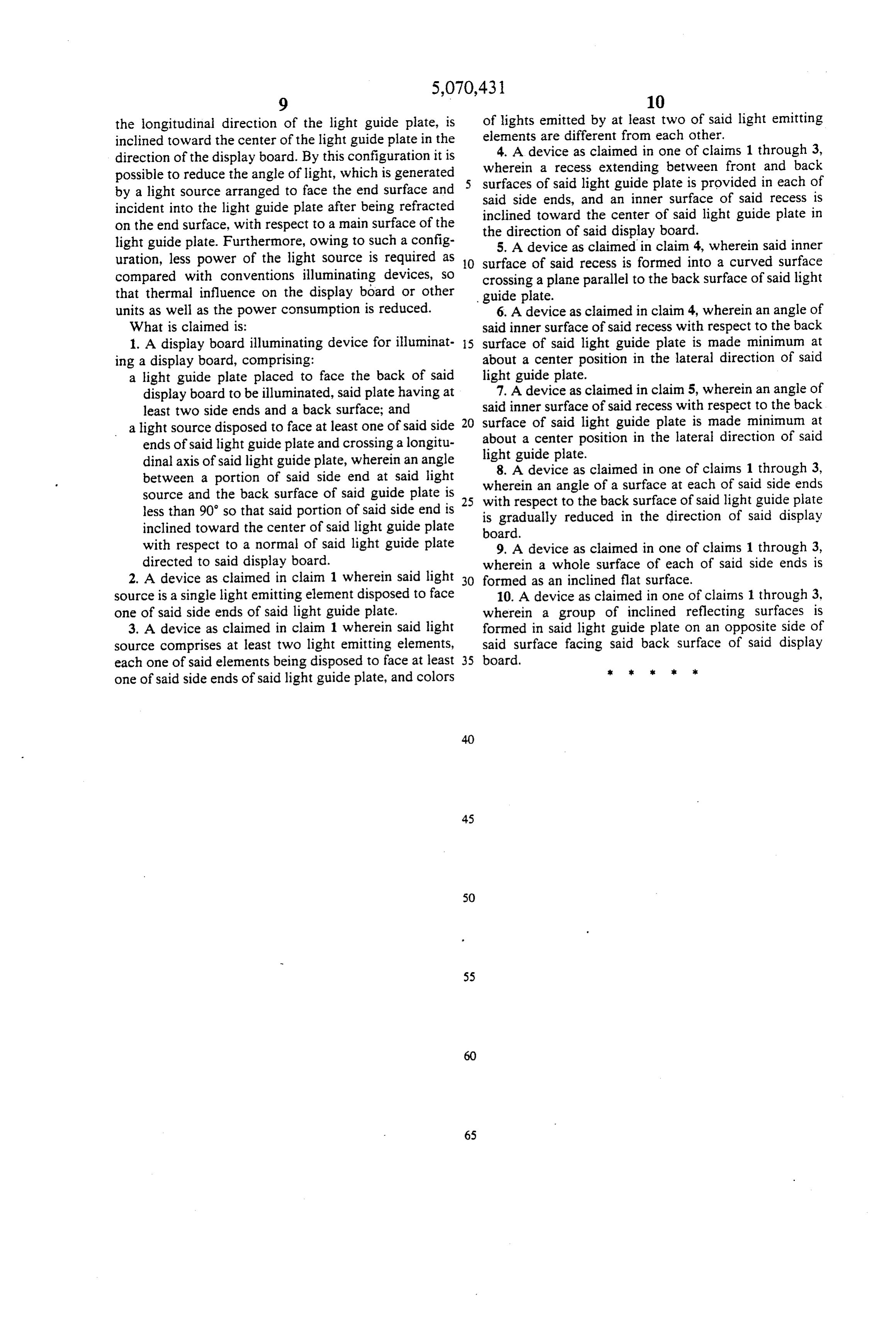
the longitudinal direction of the light guide plate, is of lights emitted by at least two of said light emitting inclined toward the center of the light guide plate in the elements are different from each other. 4. A device as claimed in one of claims 1 through 3, direction of the display board. By this configuration it is wherein possible to reduce the angle of light, which is generated surfaces a recess extending between front and back by a light source arranged to face the end surface and said sideofends, said light guide plate is provided in each of incident into the light guide plate after being refracted inclined towardand the an inner surface of said recess is center of said light guide plate in on the end surface, with respect to a main surface of the the direction of said display board. light guide plate. Furthermore, owing to such a config 5. A device as claimed in claim 4, wherein said inner uration, less power of the light source is required as 10 surface of said recess is formed into a curved surface compared with conventions illuminating devices, so crossing a plane parallel to the back surface of said light that thermal influence on the display board or other guide plate.
units as well as the power consumption is reduced. 6. A device as claimed in claim 4, wherein an angle of What is claimed is: said inner surface of said recess with respect to the back 1. A display board illuminating device for illuminat 5 surface of said light guide plate is made minimum at ing a display board, comprising: about a center position in the lateral direction of said a light guide plate placed to face the back of said light guide plate.
display board to be illuminated, said plate having at 7. A device as claimed in claim 5, wherein an angle of least two side ends and a back surface; and said inner surface of said recess with respect to the back a light source disposed to face at least one of said side 20 surface of said light guide plate is made minimum at ends of said light guide plate and crossing a longitu aboutguidea center position in the lateral direction of said dinal axis of said light guide plate, wherein an angle light
plate.
device as claimed in one of claims 1 through 3, between a portion of said side end at said light wherein an angle source and the back surface of said guide plate is 25 with respect to theofback a surface at each of said side ends surface of said light guide plate less than 90 so that said portion of said side end is is gradually reduced in the direction of said display inclined toward the center of said light guide plate board.
with respect to a normal of said light guide plate 9. A device as claimed in one of claims 1 through 3, directed to said display board. wherein a whole surface of each of said side ends is 2. A device as claimed in claim 1 wherein said light 30 formed as an inclined flat surface.
source is a single light emitting element disposed to face 10. A device as claimed in one of claims 1 through 3, one of said side ends of said light guide plate. wherein a group of inclined reflecting surfaces is 3. A device as claimed in claim 1 wherein said light formed in said light guide plate on an opposite side of source comprises at least two light emitting elements, said surface facing said back surface of said display each one of said elements being disposed to face at least 35 board. sk sk six k k one of said side ends of said light guide plate, and colors
Provenance
- Collection
- Cited prior art
- Original PDF
- patentimages.storage.googleapis.com →
- Filed
- 1990-07-30
- Pages
- 16
- Method
- pdftotext (the PDF's own text layer) + pdftoppm 300dpi page scans
- Source
- Google Patents bibliographic record
- Granted
- 1991-12-03
- Inventors
- Hideki Kitazawa; Ryohei Terada; Shogo Takeuchi; Tsutomu Kayama; Kohichi Tanimoto; Nobuo Utsugi; Yoshiaki Nagai; Pioneer Electronic Corp
- Transcribed from
- patentimages.storage.googleapis.com →