patent · US4192457
Auxiliary truck heater
11 March 1980
Page 1 — bibliographic record
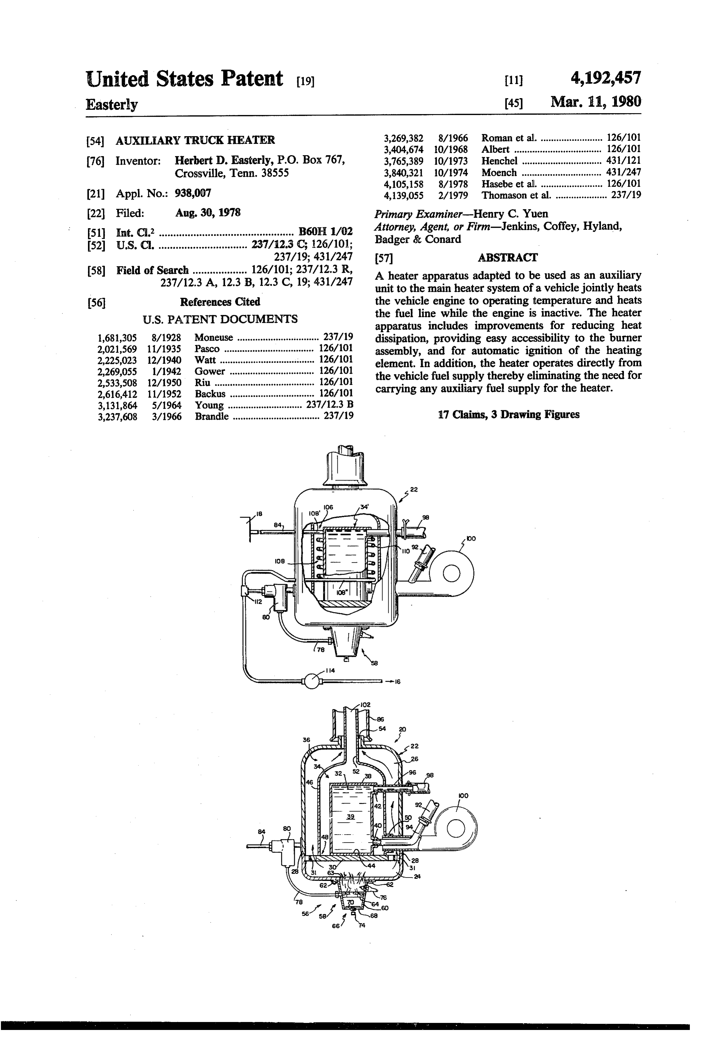
United States Patent (19) 11 4,192,457 Easterly 45) Mar. 11, 1980 54 AUXILIARY TRUCK HEATER 3,269,382 8/1966 Roman et al. ........................ 126/101 3,404,674 10/1968 Albert .......... ... 126/101 76 Inventor: Herbert D. Easterly, P.O. Box 767, 3,765,389 10/1973 Henchel ... ... 431/121 Crossville, Tenn. 38555 3,840,321 10/1974 Moench ....... ... 431/247 4,105,158 8/1978 Hasebe et al. ........ ... 126/101 21 Appl. No.: 938,007 4,139,055 2/1979 Thomason et al. .................... 237/19 22 Filed: Aug. 30, 1978 Primary Examiner-Henry C. Yuen 51) Int. C.’............................................... B60H1/02 Attorney, Agent, or Firm-Jenkins, Coffey, Hyland, 52 U.S. C. ............................... 237/12.3 (C; 126/101; Badger & Conard
58) Field of Search ................... 126/101; 237/12.3 R, A heater apparatus adapted to be used as an auxiliary 237/12.3 A, 12.3 B, 12.3 C, 19; 431/247 unit to the main heater system of a vehicle jointly heats 56 References Cited the vehicle engine to operating temperature and heats
apparatus includes improvements for reducing heat 1,681,305 8/1928 Moneuse ................................ 237/19 dissipation, providing easy accessibility to the burner 2,021,569 11/1935 Pasco ................................... 126/101 assembly, and for automatic ignition of the heating 2,225,023 12/1940 Watt ..................................... 126/101 element. In addition, the heater operates directly from 2,269,055 1/1942 Gower ................................. 126/10 the vehicle fuel supply thereby eliminating the need for 2,533,508 12/1950 Riu ....................................... 126/101 carrying any auxiliary fuel supply for the heater. 2,616,412 11/1952 Backus ................................. 126/101 3,131,864 5/1964 Young ... 237/12.3 B 3,237,608 3/1966 Brandle .................................. 237/19 17 Claims, 3 Drawing Figures
Page 2
Drawing sheet — no readable text.
Page 3
Drawing sheet — no readable text.
Page 4
AUXLARY TRUCK HEATER environment for a substantial period of time, its viscos ity tends to increase thereby retarding the flow of the fuel. Accordingly, by also preheating the diesel fuel line
The present invention relates generally to heater before attempting to start an engine which has been apparatus for vehicles, such as semi-trailer tractors, inactive for a period of time, starting is further facili which are auxiliary to the main heating system for tated.
jointly heating the vehicle engine to operating tempera The heater apparatus of the present invention solves ture and heating the vehicle passenger compartment these and other problems previously experienced with while the vehicle engine is in a down condition or not in operation. More particularly, the present invention pro 10 prior heaters by the various improvements shown in the vides an improved heater apparatus which reduces heat Figures and more completely described hereafter. dissipation, is automatically ignitable, and operates di estInconcept, accordance with the present invention in its broad there is provided an improved heater appa rectly off of the fuel supply of the vehicle. Furthermore, there is provided means for preheating the vehicle fuel ratus for jointly heating a vehicle engine to operating temperature and heating the vehicle passenger compart line before combustion. 15
Various heater systems and apparatus having previ ment while the engine is inactive. ously been developed to preheat or maintain an internal provide a heaterit isapparatus
Accordingly, a feature of the present invention to which includes a housing combustion engine at a relatively high temperature during cold weather when the engine is inactive in having two heated chambers disposed adjacent a com order to facilitate starting. For example see Thomas, 20 bustion chamber, one for heating a fluid circulated therethrough and the other for heating air circulated
U.S. Pat. No. 3,159,153; Hraboweckyj, U.S. Pat. No. therethrough thereby reducing heat dissipation through
Pat. No. 3,158,192; Holmes, U.S. Pat. No. 3,236,220; the housings of the heated chambers. Lindsey, U.S. Pat. No. 3,400,700; and Kimberlin, U.S. Another feature of the present invention is to provide Pat. No. 2,737,169. Furthermore, as is well known to 25 a heater apparatus which includes means for automati those skilled in the art, various types of heater assem cally igniting the burner assembly and in which the blies have been developed for heating the passenger burner assembly is easily accessible for servicing. compartment of the vehicle either by utilizing the heat Still another important feature of the present inven generated by the vehicle engine during its operation or tion is to provide a heater apparatus which eliminates by utilizing an auxiliary heater unit which generates its 30 the requirement for an auxiliary fuel supply by operat own heat. ing directly from the existing vehicle fuel supply. In addition to heating the vehicle engine while it is A further feature of the present invention is to pro inactive in order to facilitate starting, it is many times vide a heater apparatus as described hereinabove which also desirable to heat the passenger compartment of the includes means for preheating the fuel line prior to vehicle while the engine is inactive. For example, the 35 combustion in the engine.
passenger of the vehicle may desire to sleep in the pas Other features and advantages of the present inven senger compartment during the night, and, therefore, tion will be apparent from the following detailed de for such an extended period of time it would be desir scription of a preferred embodiment thereof, which able to turn off the vehicle engine. As disclosed by description should be considered in conjunction with Hraboweckyj in U.S. Pat. No. 3,304,004, efforts have the accompanying drawings.
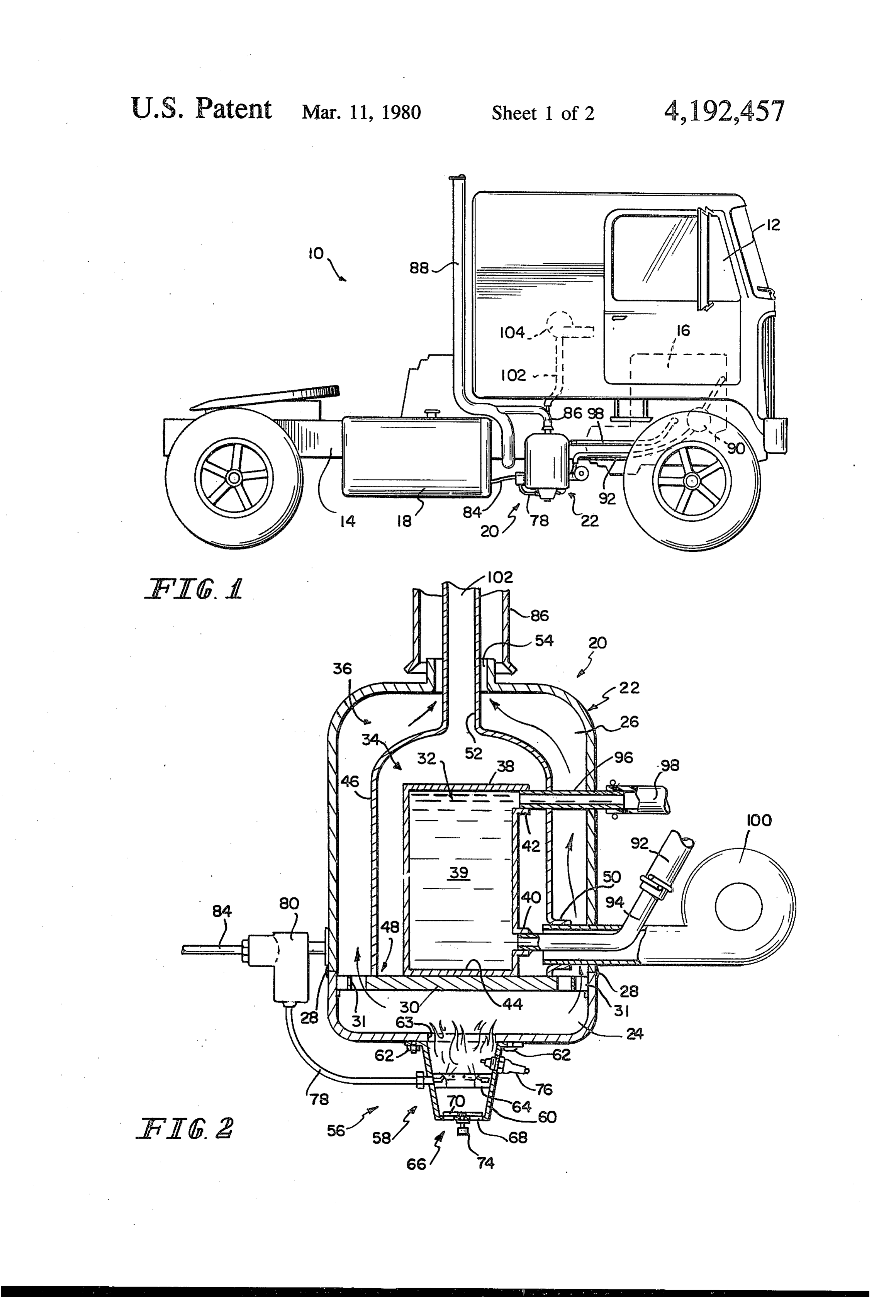
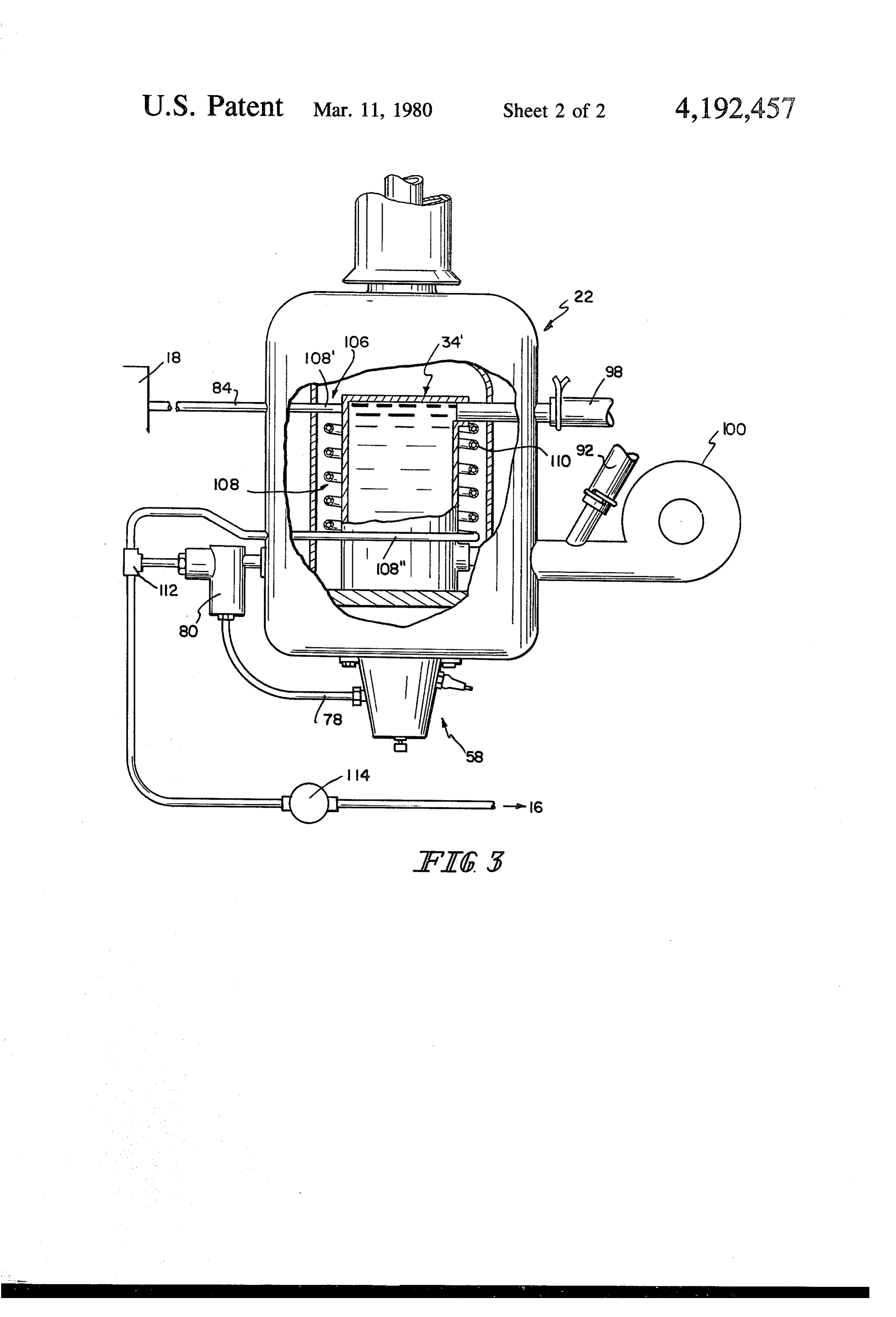
been made to combine an auxiliary heater for the vehi DESCRIPTION OF THE DRAWENGS cle engine with a heater apparatus for also heating the passenger compartment when the engine is inactive. FIG. 1 is an elevational view of a conventional semi One of the many problems which are prevalent in trailer tractor with an auxiliary heater of this invention prior heater apparatus is that they require an auxiliary 45 FIG. 2 is a transverse section through the auxiliary supply of fuel such as propane gas, butane gas or fuel oil heater of FIG. 1; and for operation (see Lindsey et al. U.S. Pat. No. 3,400,700; F.G. 3 is a modification of the auxiliary heater shown Kimberlin, U.S. Pat. No. 2,737,169; and Hraboweckyj). in FIG. with addition of a preheated fuel means. Recently it has become apparent that carrying auxiliary Referring now to the drawings, and particularly to tanks containing one or more of these fuels presents a 50 FIGS. 1 and 2, the present invention is illustratively dangerous condition due to the possibility of explosions. associated with a semi-trailer tractor 10, which would Accordingly, it is desirable and many times required include a cab 12, for the driver and passengers, a frame that an an auxiliary heater apparatus operate from the 14, supporting the cab 12, an engine 16, and fuel tanks same fuel supply as the vehicle engine. 18. Supported by a bracket (not shown) on frame 14, is Further problems which have been found to exist in 55 an auxiliary heater 20. Auxiliary heater 20 provides heat prior heater apparatus are manual ignition of the burner to the engine 16 and cab 12 when the tractor 10 is in a assembly (Hraboweckyj U.S. Pat. No. 3,304,004) and down condition, or the engine 16 is not in operation. difficulty in accessibility to the heating means for ser Auxiliary heater 20 includes a housing 22, which may vice. Most heater apparatus which supply auxiliary heat be formed in the same manner as a conventional pro to the passenger compartment also lose a considerable pane tank. Housing 22 includes a lower housing forming amount of heat by dissipation through the heater hous a lower compartment 24 and an upper housing forming ing or conduit. an upper compartment 26. The lower housing and In addition to providing a heater apparatus which upper housing have been welded or otherwise attached will jointly heat the vehicle engine and the vehicle together as indicated at 28. Located in the top portion passenger compartment while the engine is inactive, it is 65 of lower compartment 24 is a heat conducting plate 30. many times further desirable to preheat the fuel line Housing 22 encloses in the upper compartment three before combustion in the engine. It is well known that separate chambers including, a first heated chamber 32, when diesel fuel is allowed to set in a sustained cold a second heated chamber 34 and an exhaust chamber 36.
Page 5
The first heated chamber 32 includes a water tank 38 housing 22 and extends through exhaust pipe 86. Heated having an intake port 40, an exhaust port 42 and a bot air may enter cabin 12 through the normal cabin heater tom plate 44 in physical contact with heat conducting 04 or can be applied to cabin 12 through a separate plate 30. Water 39 in water tank 38 will be heated as it heating inlet.
travels between input port 40 and exhaust port 42 by 5 It has been found desirable, in some instances, partic heat being transferred from plate 30, through bottom ularly if the fuel is a diesel fuel which tends to thicken plate 44. at colder temperatures, to provide means for heating the The second heated chamber 34 includes a housing 46, fuel line prior to combustion. Assistance in atomization an intake port 50, an exhaust port 52 with a lower end of fuel in the burner assembly 58, and engine 16 can be portion 48, of housing 46, being closed by heat conduct O accomplished by a modification of the present invention ing plate 30. illustrated in FIG. 3. A portion of the auxiliary heater The exhaust chamber 36 is enclosed by housing 22 housing 22 has been broken away to illustrate a fuel and provided with an exhaust port 54. preheating means 106 located in a second heated cham Located under housing 22, for the purpose of provid ber 34. Fuel preheating means 06 includes a helical ing a heating means 56, is a burner assembly 58. Burner 15 coil 108, of heat conductive pipe 10, connected at its assembly 58 includes a cup-shaped housing 60 attached uppermost turn 108 to fuel supply conduit 84 from the by means of quick disconnect coupling 62 adjacent an fuel tank 18 and communicates at its lowermost turn opening 63 located beneath plate 30 in housing com 108" through a T-connector 12 to combination filter partment 24 for service to burner assembly 58. Burner and fuel pump 80 for burner assembly 58 and to fuel assembly 58 also includes a fuel atomizing manifold 64 20 pump 114 for engine 16. It should be understood that as located intermediate the opening 63 and an air control the second heated chamber 34 is heated, helical coil 108 means 66, located at the bottom of housing 60. Air will also absorb the heat in the same chamber 34 to control means 66 includes a plurality of apertures 68, in elevate the temperature of the fuel prior to entering the housing 60 and a rotatable plate 70 having openings pumps 80, and 14. The second heated chamber 34 is 72 to register with apertures 68 in the housing 60 and 25 heated in the same manner as that described for second vary the area of the openings available to airflow. Plate heated chamber 34 shown in FIGS. 1 and 2. Although 70 may be manually adjusted through knob 74. the coil 108 is illustrated located in chamber 34 it Intermediate the opening 63 and the fuel atomizing should be understood that coil 108 could be located on manifold 64, is a glow plug 76 for the purpose of ignit the outside of housing 22, or around conduit 102. How ing the atomized fuel from the atomizing manifold 64. ever, locating the coil 08 outside the auxiliary heater Fuel is supplied to heating means 56 by means of con 22 would result in a considerable reduction of its ability duit 78 which receives fuel from a combination filter to preheat to the fuel due to dissipation of heat to the and electric pump 80 which in turn draws fuel from surrounding ambient temperature.
conventional fuel tank 18 by way of a conduit 84. What is claimed is:
As auxiliary heater 22 is electrically energized by an 35 i. Heater apparatus comprising a housing including a electronic control means (not shown), electricity will be heating means adjacent its lower end, a wall of ther delivered to glow plug 76 and pump 80 to deliver and to mally conducting material heated by said heating means ignite and burn the fuel delivered from pump 80 to and an exhaust opening adjacent its upper end, heating means 56. Fumes from heating means S6 are a first heated chamber for liquid within said housing permitted to exit into chamber 36 through a grill 31, and formed in part by said wall of thermally con located at the periphery of and integral with heat con ducting material, ducting plate 30. As the exhaust fumes travel upwardly a second heated chamber for air surrounding said first through grill 31, they pass through the exhaust chamber heated chamber within the housing and formed in 36 between housing 46 and housing 22, and continue on part by the wall of thermally conductive material, to exit through exhaust port 54 in housing 22. As seen in 45 an opening in the wall of thermally conducting mate FIG. 1, exhaust fumes can be removed from auxiliary rial to direct the exhaust of the heating means heater 22 through an intermediate exhaust pipe 86 within said housing and around said first and sec which communicates with the conventional exhaust ond heated chambers to said exhaust, stack 88 of the tractor 10. said heater apparatus being capable of simultaneously As heater means 56 continues to operate, it will heat 50 heating a liquid and air while reducing heat lost the heat conducting plate 30, to increase the tempera from said first and second chambers and while ture of the water 39 in first heated chamber 32. A circu isolating exhaust of said heating means from the air lation pump 90, as seen in FIG. 1, will circulate water 39 being heated.
from the engine block 16 through a lower heater hose 2. Heater apparatus comprising a housing including 92 attached to a pipe 94 into intake port 40 of the water 55 an exhaust port and heating means detachably coupled tank 38. As the water 39 is heated it moves out of water thereto, a first heated chamber disposed within the tank 38, through exhaust port 42, through pipe 96 and housing for heating a fluid circulated therethrough and upper heater hose 98, and back into the engine block 16 a second heated chamber disposed within the housing to complete the flow of water 39 from the engine block and encompassing the first heated chamber for heating 16 through the pump 90, into the tank 38, and back air circulated therethrough, and the exhaust of the heat again into the engine block 16. ing means is directed within the housing and around Second heated chamber 34 receives heat from the said second heated chamber and the air is heated by the heat conducting plate 30 and from heat transferred heat transferred from the first heated chamber and through housing 46 from exhaust chamber 36. The through the second heated chamber housing from the heated air in the chamber 34 is moved by means of a 65 exhaust of said heating means, wherein the housing blower 100, communicating with intake port 50, includes an upper compartment and a lower compart through chamber 34, and out through exiting conduit ment separated by a heat conducting plate, the upper 102 into the cab 12. Exiting conduit 102 is connected in compartment comprising an exhaust chamber which
Page 6
S 6 includes the exhaust port, and the lower compartment 10. The apparatus as recited in claim 9 wherein the comprising a burner assembly which includes the heat formed means for heating the second fluid includes a coil ing means for heating the heat conducting plate, the about the first heated chamber. heat conducting plate including a grid located in the engine and 11. In a heater apparatus adapted to heat a vehicle periphery thereof for permitting exhaust fumes to exit while the engine heat the vehicle passenger compartment through the exhaust chamber. is inactive including heating means for simultaneously heating a fluid circulated through the 3. The apparatus as recited in claim 2 wherein the housing includes means for automatically igniting the vehicle engine and for heating air circulated through the vehicle compartment, the improvement wherein heating means. 10 said means includes heat conductive walls forming first 4. The apparatus as recited in claim 3 wherein the and second chambers for fluid and air, said walls are means for automatically igniting the heating means disposed within a housing so that said first and second includes a glow plug which when activated ignites a chambers are within an exhaust chamber of said heating fuel causing the fuel to burn. means, said first and second chambers sharing one of 5. The apparatus as recited in claim2 wherein the first 15 said walls which is in direct conductive heat transfer and second heated chambers are disposed within the relation with said exhaust chamber and the air and fluid exhaust chamber of the housing whereby heat dissipa are heated by the heating means and its exhaust by heat transferred through the walls of the first and second tion through the housings of the first and second heated chambers.
chambers is substantially decreased.
6. The apparatus as recited in claim 5 wherein the first the12.heating
The improvement as recited in claim 11 wherein
means includes means for automatically heated chamber includes an intake port and an exhaust igniting the heating means.
port for circulating the fluid through the chamber and a 13. The improvement as recited in claim 12 wherein lower surface in physical contact with the heat conduct means for automatically igniting the heating means ing plate for heating the fluid as it circulates through the 25 includes an electric fuel pump and a glow plug which chamber. when activated ignite and burn the fuel delivered by the 7. The apparatus as recited in claim 6 wherein the pump.
second heated chamber includes an intake port in com 14. The improvement as recited in claim 11 further munication with a blower assembly and an exhaust port comprising a fuel preheating means disposed within the for circulating air through the second heated chamber 30 second chamber and interposed between a vehicle fuel and is closed at one end by the heat conducting plate for supply and the vehicle engine.
heating the air as it circulates through the chamber. 15. The improvement as recited in claim 14 wherein 8. The apparatus as recited in claim 7 further includes the fuel the preheating means is further interposed between vehicle fuel supply and the heating means.
an exhaust pipe coupled to the exhaust port of the com 35 16. The improvement as recited in claim 15 wherein bustion chamber and an exiting conduit coupled to the the fuel preheating means includes a coil formed about exhaust port of the second heated chamber, the exiting the first chamber having its uppermost portion coupled conduit being disposed within the exhaust pipe whereby to the vehicle fuel supply and its lowermost portion heat dissipation from the exiting conduit is substantially coupled to the vehicle engine and the heating means. decreased. 17. Apparatus to heat simultaneously a vehicle en 9. Heater apparatus comprising a housing having an gine, and passenger compartment, comprising upper portion which includes an exhaust port and a a housing, lower portion which includes a detachable heating means to provide heat within the housing, means, a first heated chamber disposed within the hous 45 a first chamber within said housing for fluid to be ing for heating a fluid circulated therethrough, a second circulated through the vehicle engine, and a second heated chamber disposed within the housing and hous chamber within said housing for the circulation of ing the first heated chamber for heating air circulated air to the passenger compartment, therethrough said first and second chambers sharing a said first and second chambers sharing a common common heat conductive wall which is in direct con heat conductive wall and each being surrounded ductive heat exchange relation with said heating means, by and in direct conductive heat transfer relation with an exhaust chamber of said heating means to and means disposed within the second heated chamber provide simultaneous heating of fluid for the vehi for heating a second fluid circulated therethrough cle engine and air for the passenger compartment whereby the air and second fluid are heated by heat and to reduce the heatioss from said first and sec transferred from said heating means to the second 55 ond chambers.
heated chamber.
Provenance
- Collection
- Cited prior art
- Original PDF
- patentimages.storage.googleapis.com →
- Filed
- 1978-08-30
- Pages
- 6
- Method
- pdftotext (the PDF's own text layer) + pdftoppm 300dpi page scans
- Source
- Google Patents bibliographic record
- Granted
- 1980-03-11
- Inventors
- Herbert D. Easterly
- Transcribed from
- patentimages.storage.googleapis.com →