patent · US5365920
Solar concentrator system
22 November 1994
Page 1 — bibliographic record
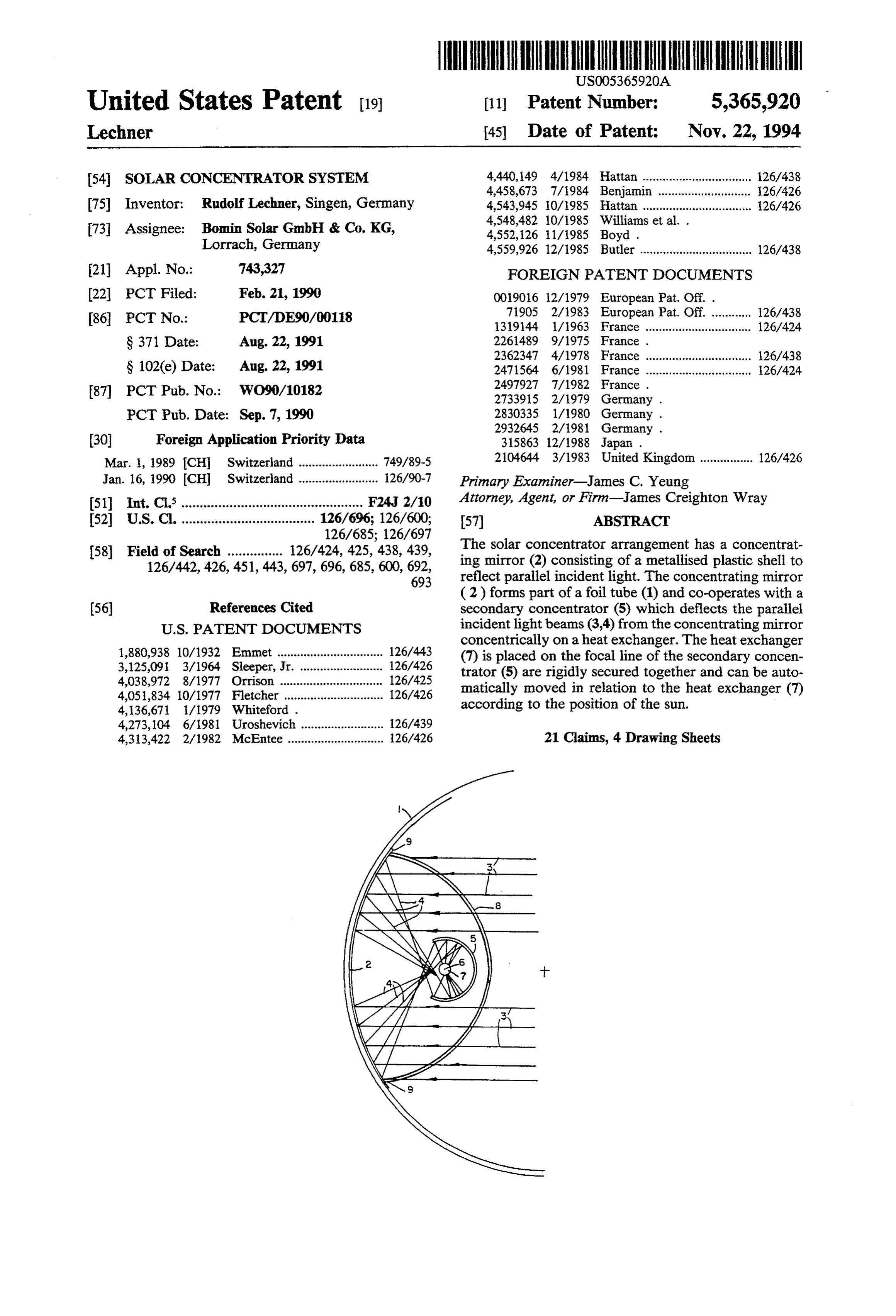
United States Patent (19) 11 Patent Number: 5,365,920 Lechner 45) Date of Patent: Nov. 22, 1994 54 SOLAR CONCENTRATOR SYSTEM 4,440,149 4/1984 Hattan ................................. 26/438 4,458,673 7/1984 Benjamin ............................ 126/426 (75) Inventor: Rudolf Lechner, Singen, Germany 4,543,945 10/1985 Hattan ................................. 26/426
73 Assignee: Bomin Solar GmbH & Co. KG, 4,552,126 11/1985 Boyd .
Lorrach, Germany 4,559,926 12/1985 Butler .................................. 126/438 21 Appl. No.: 743,327 FOREIGN PATENT DOCUMENTS 22 PCT Filed: Feb. 21, 1990 0019016 12/1979 European Pat. Off. . 86 PCT No.: PCT/DE90/00118 71905 2/1983 European Pat. Off. ............ 26/438 1319144 1/1963 France ................................ 126/424
S 371 Date: Aug. 22, 1991 2261489 9/1975 France . 2362347 4/1978 France ................................ 126/438
S 102(e) Date: Aug. 22, 1991 2471564 6/1981 France ................................ 26/424
87 PCT Pub. No.: WO90/10182 2733915 2/1979 Germany . PCT Pub. Date: Sep. 7, 1990 2830335 1/1980 Germany .
30 Foreign Application Priority Data 315863 12/1988 Japan.
Mar. 1, 1989 CH Switzerland ........................ 749/89-5 2104644 3/1983 United Kingdom ................ 126/426 Jan. 16, 1990 (CH) Switzerland ........................ 126/90-7 Primary Examiner-James C. Yeung 51 int. Cl. ................................................. F24, 2/10 Attorney, Agent, or Firm-James Creighton Wray 52 U.S. Cl. .................................... 126/696; 126/600; 57 ABSTRACT 126/685; 126/697 The solar concentrator arrangement has a concentrat 58 Field of Search ............... 126/424, 425, 438, 439, ing mirror (2) consisting of a metallised plastic shell to 126/442, 426,451, 443,697, 696, 685, 600, 692, reflect parallel incident light. The concentrating mirror
(2) forms part of a foil tube (1) and co-operates with a (56) References Cited secondary concentrator (5) which deflects the parallel
concentrically on a heat exchanger. The heat exchanger 1,880,938 10/1932 Emmet ................................ 126/443 (7) is placed on the focal line of the secondary concen 3,125,091 3/1964 Sleeper, Jr. ......................... 126/426 trator (5) are rigidly secured together and can be auto 4,038,972 8/1977 Orrison ....... ... 126/425 matically moved in relation to the heat exchanger (7) 4,051,834 10/1977 Fletcher .............................. 126/426 according to the position of the sun.
4,273,104 6/1981 Uroshevich ......................... 126/439 4,313,422 2/1982 McEntee ............................. 26/426 21 Claims, 4 Drawing Sheets
Page 2
Drawing sheet — no readable text.
Page 3
Drawing sheet — no readable text.
Page 4
Drawing sheet — no readable text.
Page 5
Drawing sheet — no readable text.
Page 6
SOLAR CONCENTRATOR SYSTEM DETAILED DESCRIPTION OF THE
DRAWINGS
The present invention refers to a solar concentrator The Solar concentrator system according to the in system comprising at least one metallized foil strip and 5 Vention comprises a concentrator mirror having a met heat exchanger means located in front of said metallized allized plastic foil to reflect solar radiation hitting the foil strip such that solar radiation hitting on the metal reflecting surface in parallel relationship. The concen lized surface of said metallized foil strip is reflected trator mirror of the invention is used in place of the towards said heat exchanger means. cylindrical parabolic concentrators made of mirror O glass and should provide an equal or even a better con
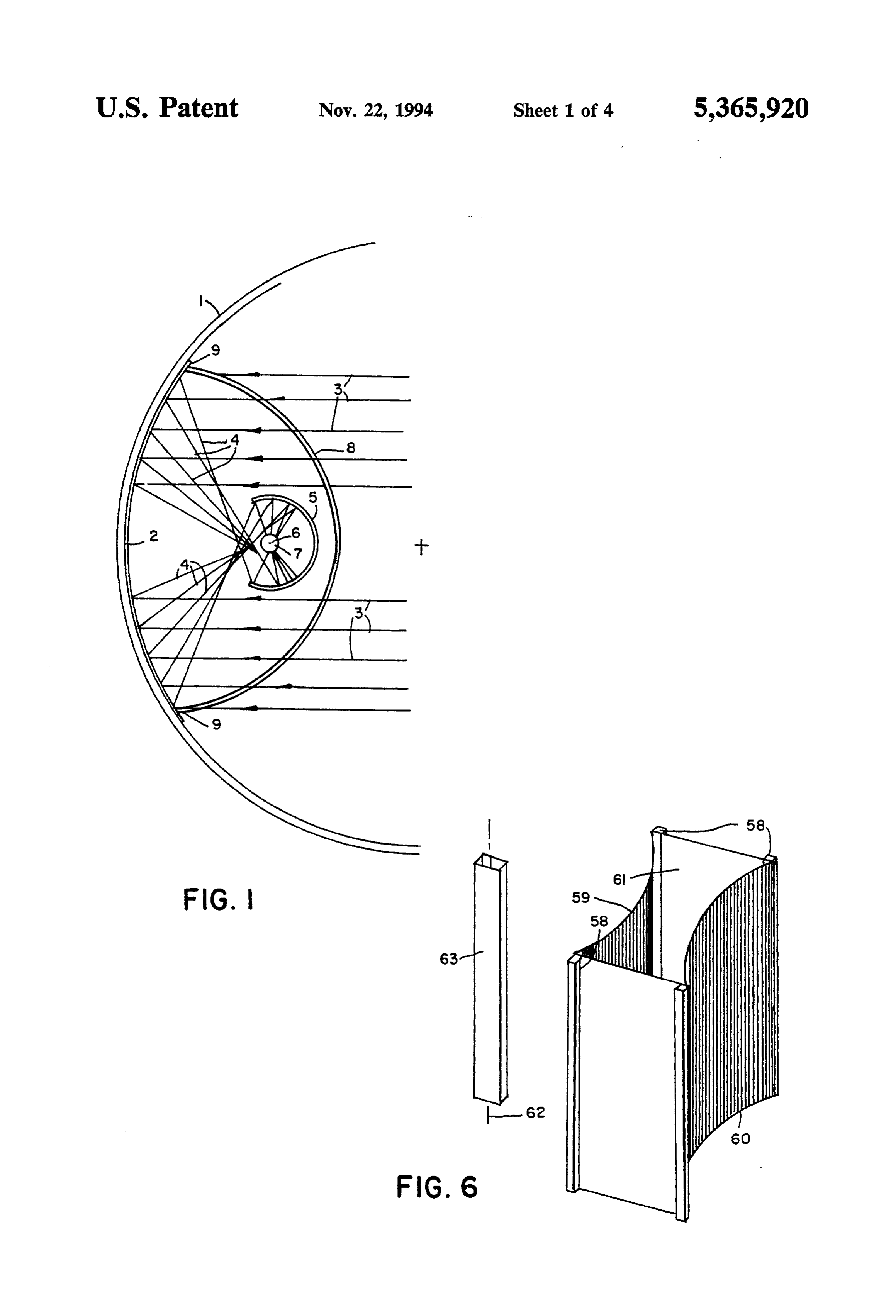
BACKGROUND OF THE INVENTION centration of the solar radiation hitting the surface of Known solar concentrator systems usually comprise the concentrator. The concentrator mirror of the inven heavy reflector elements made of glass and/or metal tion is located on a portion of a plastic foil having circu which are expensive to manufacture because their shape lar cross-section, e.g. on a partial face of a circular cyl must be finished very accurately. In the past, it has been 15 inder jacket. For this purpose, a tubular foil 1 is used proposed to make use of lighter foil mirrors instead of which is highly transparent and comprises circular cy the heavy glass or metal mirrors. Thereby, a metallized lindrical shape in cross-section. Such a shape is assured foil is tentered over a frame made of fibre composite by providing a pressure in the interior of said tubular material and brought into a parabolic shape. Thus, the 20 foil 1 which is higher than atmospheric pressure. In weight of such a mirror element is approximately one view FIG. 1 of the drawings, only a partial cross-sectional quarter of the weight of a comparable mirror element of a tubular foil 1 is shown. made of glass or metal. Such a solar concentrator sys A strip-like portion of the tubular foil 1 is provided tem comprises an essentially inexpensive, lightweight with a metallized reflecting layer forming a concentra concentrator incorporating a metallized plastic foil with 25 tor mirror 2 for reflecting solar radiation 3 impinging on fixed focus. On the other side, the frame must be pre its metallized surface in parallel relationship. This solar radiation 3 being parallely incident is reflected by the cisely and expensively manufactured to the calculated metallized shape whereby even minor deviations from the ideal or whereby thesurface of the concentrator mirror 2 reflected rays 4 impinge on the concave theoretically required shape result in a substantial deg inner surface on a secondary concentrator 5. The latter radation of the efficiency of the system. 30 one is in the shape of a cylindrical jacket as well and is SUMMARY OF THE INVENTION curved and located in such a way that the entire bundle It is an object of the present invention to provide an of rays exactly impinges on the focus line 6 of the sec ondary concentrator 5. Thus the secondary concentra improved solar concentrator system. tor 5 forms a cylindrical hollow space light trap which Features of the invention are set forth in claim 1.
Thus, the expensive, fragile, heavy and optically inac istralmetallized over its entire inner surface and has a cen
focus line 6.
curate parabolic cylinder mirrors can be replaced by A heat exchanger in the form of a tube 7 extends inexpensive, light and unbreakable mirrors with high along the focus line 6, and a heat carrier liquid circulates optical precision. The circular cylinder face can be through the tube 7 and is heated under the influence of realized easily with the required accuracy. By means of 40 the concentrated solar radiation. a secondary concentrator mirror, the final focusing of Advantageously the design of the entire solar concen the solar radiation can be effected. trator system is such that the central axis of the tube 7 Expedient embodiments of the invention are set forth runs exactly horizontally from east to west (see FIG.2). in the dependent claims 2-20. A process of manufactur The parallel light rays 3 form a plane together with this ing is described in claim 21. 45 east-west-axis of the heat exchanger tube 7, the eleva BRIEF DESCRIPTION OF THE DRAWINGS tion angle of this plane being 0 at sunrise and sunset and taking a certain maximum value at noon in response to
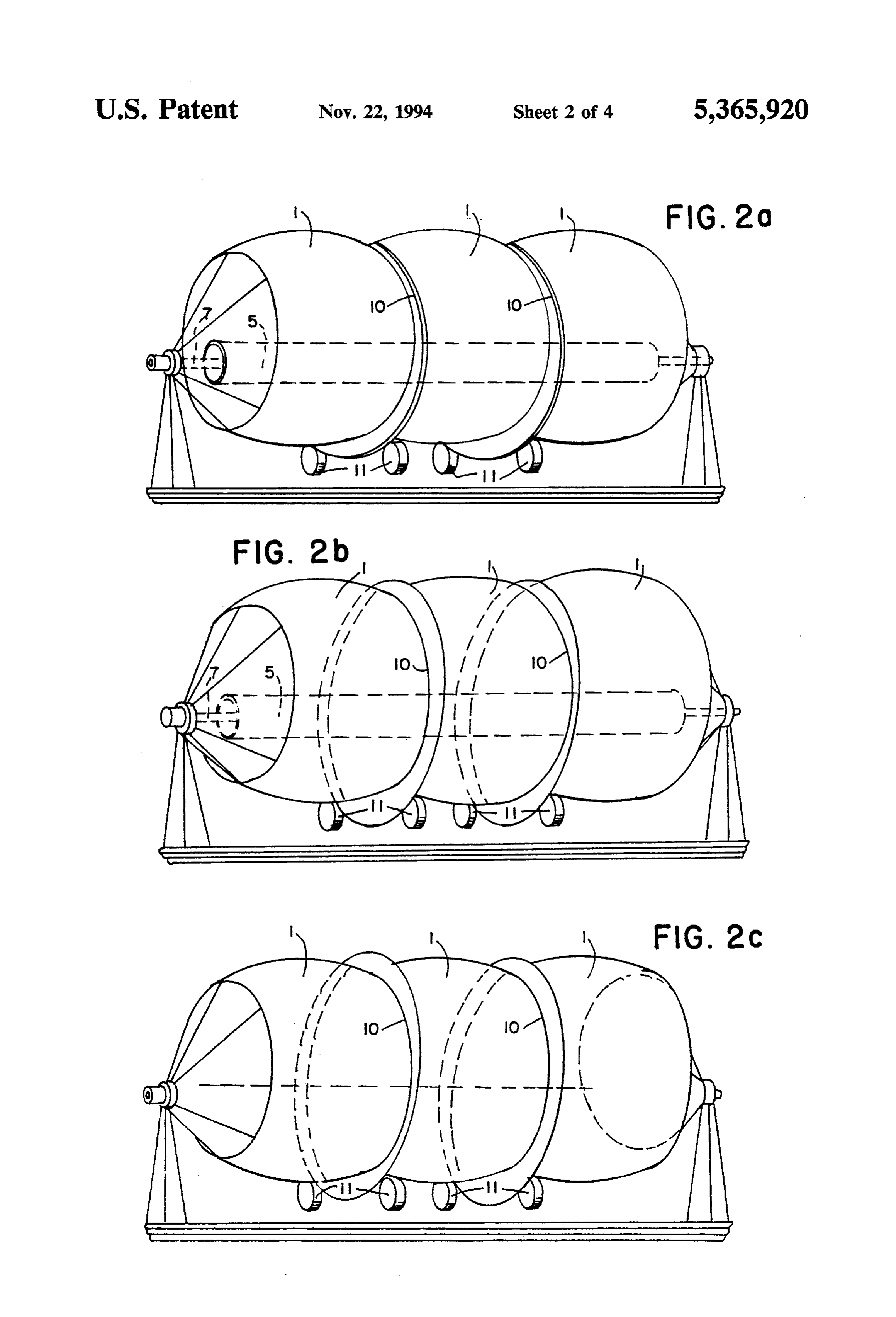
In the following, some embodiments of the solar the changing of the seasons. If the concentrator mirror concentrator system of the invention will be further 2 is rotated around the axis of the heat exchanger tube 7, described, with references to the accompanying draw 50 the latter one is maximally subjected to solar radiation ings, in which: during all the day; thereby, the heat exchanger 7 itself is FIG. 1 shows the basic design of a solar concentrator not rotated and can be connected directly to a heat system according to the invention in a cross-sectional recovering system without the need to provide expen view; sive coupling means. However, it is essential that the FIG. 2A shows a schematic view of the design; 55 concentrator mirror 2 and the secondary concentrator 5 FIG. 2A shows a schematic view of another embodi are rigidly connected to each other to form an integral ment; constructive unit which is automatically rotated in re FIG. 2C shows a schematic with the clamping rails; sponse to the position of the sun. FIG. 3 shows a diagram to explain the theoretical Another possibility is to design the tubular foil 1 as basics of a preferred embodiment of the invention; well as the concentrator mirror 2 immovable and rigid FIG. 4 shows a schematic perspective view of a fur while the heat exchanger tube 7 is adjusted along a ther embodiment of the solar concentrator system ac circular path in response to the position of the sun. In cording to the invention; this case the heat exchanger tube 7 is cranked and com FIG. 5 shows a side view of a further embodiment of prises an angled leg which is adjustable relative to said the solar concentrator system according to the inven 65 integral constructive unit in response to the position of tion; and the sun.
FIGS. 6-8 show schematic views of further variants However, it must be mentioned that a larger portion of the proposed solution. of the tubular foil 1 must be metallized in this case with
Page 7
the result that the concentrator mirror 2 has greater by means of pressurized air. The entire arrangement is dimensions. Another possibility is to provide a much such that the two diametrally opposite clamping rail smaller foil; in place of the tubular foil 1 a foil element pairs are rotatably connected to the supporting frames 8 (FIG. 1) is provided which has lens-shaped cross-sec with the result that the inflated tubular foil may be tion and comprises a corresponding reflecting layer. rotated around a horizontal axis in response to the posi Again, the so formed lens-shaped envelope is closed at tion of the sun. It is understood that the two ends of the both ends and tensioned by an interior pressure which is so formed plastic foil tube are closed in a suitable man higher than the atmospheric pressure. In most cases it is ner known per se and readily present to any person necessary to provide an additional supporting frame skilled in the art. In the embodiments described herein keeping the four corners 9 of the lens-shaped envelope 10 above the concentrator mirror has been located on a in position. plastic foil having circular cylindrical shape, and a strip Coming back to the embodiment with a tubular foil 1 of the plastic foil running parallel to the axis of the in the shape of a circular cylindrical jacket, it must be cylinder is provided with a metallized layer serving as a mentioned that the plastic envelope tensioned by inter reflecting face to concentrate the solar radiation hitting nal pressure is provided with support rings 10 located a 15 on this face. The width of the strip is limited to an open certain distance from each other and extending in paral ing angle at which all incident terminal rays are re lel vertical planes. This additional measure is particu flected to the focus line within an acceptable optical larly essential if the tubular foil 1 has a great length. By error. Due to optical reasons this angle shall be not the provision of the support rings 10 the plastic enve more than approximately 30 . Using such an opening lope will take a barrel-like shape with the result that the 20 angle a concentration factor of approximately c=46 inner surface is provided with an astigmatic mirror face. can be achieved, which is high enough to sufficiently The tubular foil 1 with its support rings 10 rests on heat a heat exchanger arranged in the focus line. How rollers 11 in order to enable the tubular foil 1 to be ever, if the diameter of the cylindrical tubular foil is not rotated in response to the position of the sun. to exceed a still acceptable size the reflecting strip is In the heat exchanger tube 7 of the solar concentrator 25 quite narrow, with the result that only little radiation is system a heat carrier liquid is heated up and circulated trapped and concentrated in the focus line. If the re through a steam generator to produce overheated steam flecting strip is made larger the solar rays in the edge which drives a turbine with a generator to produce portions are not reflected to the focus line of the mirror electrical current. . and do not assist in heating the heat exchanger due to A further possibility, not shown in the drawings, 30 spheric aberration and due to caustic.
consists of providing the inner surface of an air-inflated In order to avoid this disadvantage, it has been sug tent with a metallized layer to form a concentrator gested to use a secondary concentrator which is hit by mirror. In the interior of that air-inflated tent an integral the rays caustically reflected by the edge portions of the constructive unit consisting of a secondary concentra metallized strip and which reflects the rays concentrat tor and a heat exchanger tube is adjustably arranged to 35 edly to a heat exchanger located in the focus line of the be moved along a circular path in response to the posi secondary concentrator. However, the use of a second tion of the sun. ary concentrator can be avoided, as will be explained in In the designs comprising a longitudinal plastic enve the following with reference to FIGS. 3-8. lope with circular cylindrical cross-section, it is advan The basic aim is to provide a solar concentrator sys tageous to use support members which are connected to tem having a width not greater than a solar concentra pillow blocks located at both ends of the plastic enve tor design with a cylindrical inflated tubular plastic foil lope to form a rigid frame. The support members can be but which yields a much higher efficiency even if only designed as rigid semicircular rings or as closed rope One concentrator mirror and embodiment, it shall be loops. It is understood that both kinds of support mem possible to arrange the heat exchanger outwards of the bers can be combined. Particularly the upper support 45 pressurized space.
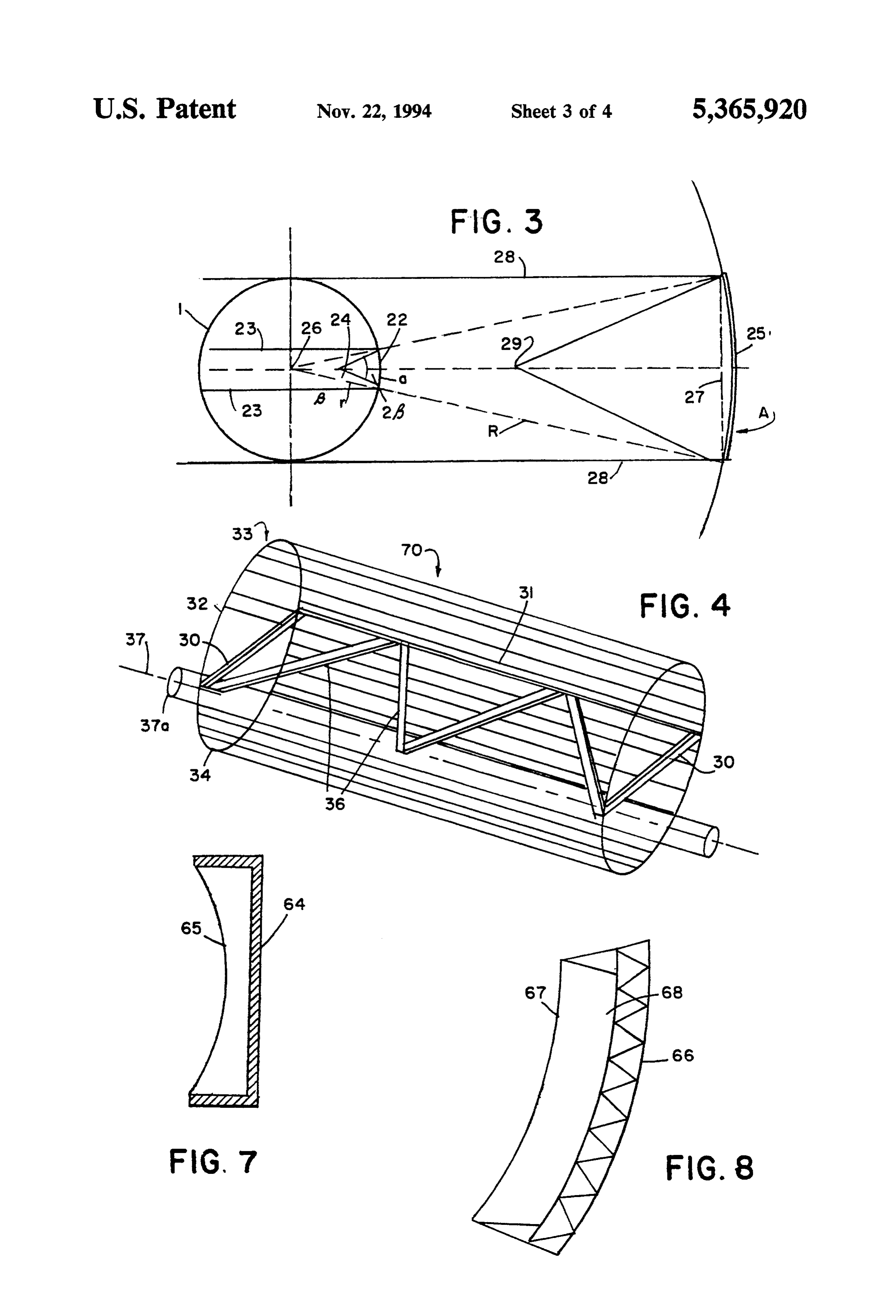
ring can be rigid and the lower support member can In a first approach, the theoretical basis of the pro consist of a rope loop which is tensioned as soon as the posed embodiments will be further explained with refer plastic envelope is filled with pressurized air. ence to FIG. 3.
Further, the invention provides a method for manu In FIG. 3 there is provided a highly transparent plas facturing a solar concentrator system. In a first step, a SO tic tube 21 having circular cross-section and being pres tubular plastic foil is manufactured, e.g. by means of an surized in its interior. The plastic tube 21 comprises a annular nozzle. Thereafter this tubular plastic foil is strip-like portion 22 which is provided with a reflecting separated into two equal webs whereby one of the webs layer. The width of the strip-like portion 22 is chosen or sometimes both webs are provided with a reflecting such that the strip includes an area in the region of a layer on predetermined portions of the interior of the 55 central angle (3=30'. The radius of the cylindrical plas web. This layer will form the concentrator mirror. Fur tic tube 21 is designated with r and the arc length corre ther, at the beginning and at the end of the solar concen sponding to the width of the strip-like portion 22 is trator system a pillow block or a supporting frame is designated with a. In this design only the marginal rays erected and clamping rails are arranged between said 23 are reflected to the focus line 24 of the strip 22 serv pillow blocks or supporting frames which extend in ing as a mirror; the reflection takes place under a con horizontal direction along the entire length of the plas vergence angle of approximately 2,3=60. tic foil webs. The clamping rails serve to clamp the Now the solely effective section of the cylindrical corresponding longitudinal edges of the two webs plastic tube 21, i.e. the strip-like portion 22, is enlarged which are put together to a tubular form again. How according to the law of similarity by projecting it to an ever, prior to interconnecting the two webs, the second 65 arc-shaped strip 25 having the same central axis 26 as ary concentrator and the heat exchanger are arranged the cylindrical plastic tube 21 and having a radius R at within the frame formed by the clamping rails and the which the chord 27 is not greater than the diameter r of pillow blocks. In a final step the tubular foil is inflated the plastic tube 21. The arc-shaped strip 25, which is
Page 8
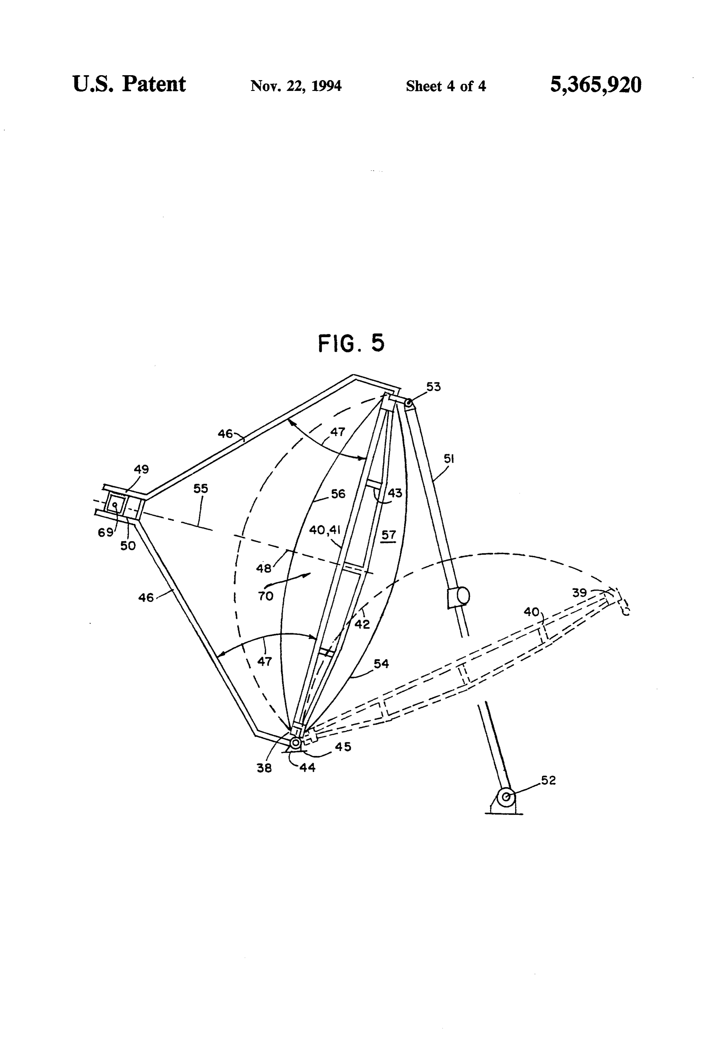
well defined in this manner, is provided with a reflect Another embodiment of the solar concentrator sys ing layer reflecting all incident solar radiation as far it is tem according to the invention is shown in FIG. 5, within the marginal rays 28 into the focus line 29. which exhibits a schematic lateral view. In this embodi It can further be seen in FIG. 3 that in using the ment a frame 70, including longitudinal struts 38 and 39 conventional design with a plastic tube 21 having a and transverse struts 40 and 41, is used and the rigidity radius r, the really effective projection area corresponds of this frame is enhanced by slightly curved auxiliary to an area which is defined by the width of the strip-like struts 42 and distance pieces 43. The frame 70 is pivot portion 22. The strip-like portion 22 is well defined by ally supported in a bearing member 44 and can be ro the central angle f3=30 and by the convergence angle tated in a vertical plane. The pivotaxis 45 of the bearing of 26=60 at a predetermined radius r. Therefrom the 10 member 44 is close to the floor and extends in horizontal arc length a of the strip-like portion 22 which is relevant direction parallel to the longitudinal struts 38 and 39. for the area can easily be calculated: a = 2-r-pi/p3. The Furthermore, the frame 70 is provided with two can arc length A of the strip 25 can be calculated in the same tilever arms 46 which are connected to the frame 70 in manner: A=2-R-pi/g. It follows: a/A=r/R=sin the region of its longitudinal struts 38 and 39, which B/2=sin 15 = 0.25882. Finally, the result therefrom is: 15
A=1/0.25882 =3.86637-a. At the same space require include with the plane of the frame 70 the same angle 47 and which form a fixture 49 located in the region of a ments determined by the radius r a nearly four times central plane 48 extending perpendicularly to the frame bigger area can be used to effectively trap incident solar 70. The fixture 49 is located exactly in the focus line 69, radiation. It shall be mentioned that an approximately which extends exactly perpendicularly to the drawing forty times bigger concentration of the received solar 20 plane.
energy results at the chosen central angle of 30; there which The focus line 69 belongs to a reflecting foil strip is connected to the frame 70, as will be further fore enough heat energy is present to sufficiently heat a described hereinbelow. The two cantilever arms 46 are heat exchanger.
Thus, according to the invention, a plastic tube is not fixed to the frame 70 in such a manner that they are used any longer but a metallized foil strip which is 25 noved together with the frame 70, with the result that evenly curved around its longitudinal central axis and the position of the fixture 49 always remains in the focus calculated according to the preceding explanations, line 69. A heat exchanger 50 is mounted in the fixture whereby a heat exchanger is arranged in the focus line 49; the heat exchanger 50 extends exactly along the of the curved metallized foil strip. focus line 69 and a heat carrier liquid circulates in the A practical embodiment of a foil strip suitable for the heat
exchanger 50.
enable the frame 70 including the heat exchanger construction of a solar concentrator system is shown in
FIG. 4. 50 to be pivoted and fixed in a desired position, a tele After the length of the chord 27 having been calcu Scopic tube 51 is provided which is pivotally connected lated according to the preceding explanations, a frame is to a bearing 52 at its one end, and at its other end by a built having rectangular shape and comprising two 35 connecting member 53 to the upper longitudinal struts short struts 30 as well as two long struts 31. The length 39. By reducing the length of the telescopic tube 51, the of the short struts 30 corresponds to the calculated frame 70 can be pivoted from the position shown in length of the chord 27, while the length of the longer solid lines to the position shown in dashed lines. struts 31 results from practical and constructive point of The side of the frame 70 remote from the heat ex weWS. 40 changer 50 is provided with a reflecting foil strip 54 the A rectangular plastic foil 32 being provided with a width thereof is calculated as described hereinabove metallized reflecting layer is fixed to the two longer and which forms a reflecting mirror having a focus line struts 31 along its edges, these longitudinal edges having 69 located in the central axis of the heat exchanger 50. the same length as the struts 30. The length of the trans The other side of the frame 70 facing the heat ex verse edge 33 of the reflecting plastic foil 32 corre 45 changer 50 is provided with a transparent foil 56, and sponds to arc-length A in FIG. 3 and can be calculated the space 57 between the two foils 54 and 56 is air accordingly by assuming a central angle (3=30 again. tightly sealed at both ends by means of suitable covering Thus, the reflecting plastic foil 32 can be exactly cut to members (not shown). Thus, a pressure which is higher the proper size and connected to the two longer struts than the atmospheric pressure can be created in the 31 at one side of the frame. 50 space 57 between the two foils, whereby the two foils In addition, a transparent foil 34 having the same size are tensioned and the reflecting foil strip 54 will take the as the plastic foil 32 is connected to the longer struts 31 predetermined and calculated shape. on the other side of the frame, with the result that a A further embodiment of the solar concentrator sys tube-like member is formed which is air-tightly sealed at ten according to the invention is schematically shown both ends. For this purpose (not shown) cover foils 35 55 in FIG. 6. Here a frame 58 is used which is covered at are used. In order to enhance the rigidity of the frame, one side thereof with a reflecting foil 60 which must not a number of transverse struts 36 are provided which be transparent. The frame 58 is completely sealed such interconnect the two longer struts 31. that an air-tight space 61 results between the two foils A receiver tube 37a is arranged in the focus line 37 of 59 and 60 which is evacuated. Thereby the reflecting the reflecting foil 32, and a heat carrier liquid is circu 60 foil 59, as well as the inexpensive foil 60, will take the lated through the receiver tube 37a. Depending on the desired shape which has been calculated as hereinbefore size of the reflecting foil 32, the focus line is located described. A heat exchanger 63 is arranged in the focus within or beyond the space limited by the reflecting foil line 62 of the reflecting foil 59, whereby the construc 32 and the transparent foil 34, which results after said tive details will not be further discussed here since they space having been filled with pressurized air. Thereby 65 are readily present to any person skilled in the art. the foils 32 and 34 are tensioned and take the operating Again, the central angle amounts to 30' and the conver position. Furthermore, the focus line 37 must be ad gence angle amounts to 60, with the result that a con justed according to the east-west-axis. centration factor of c=46 can be achieved.
Page 9
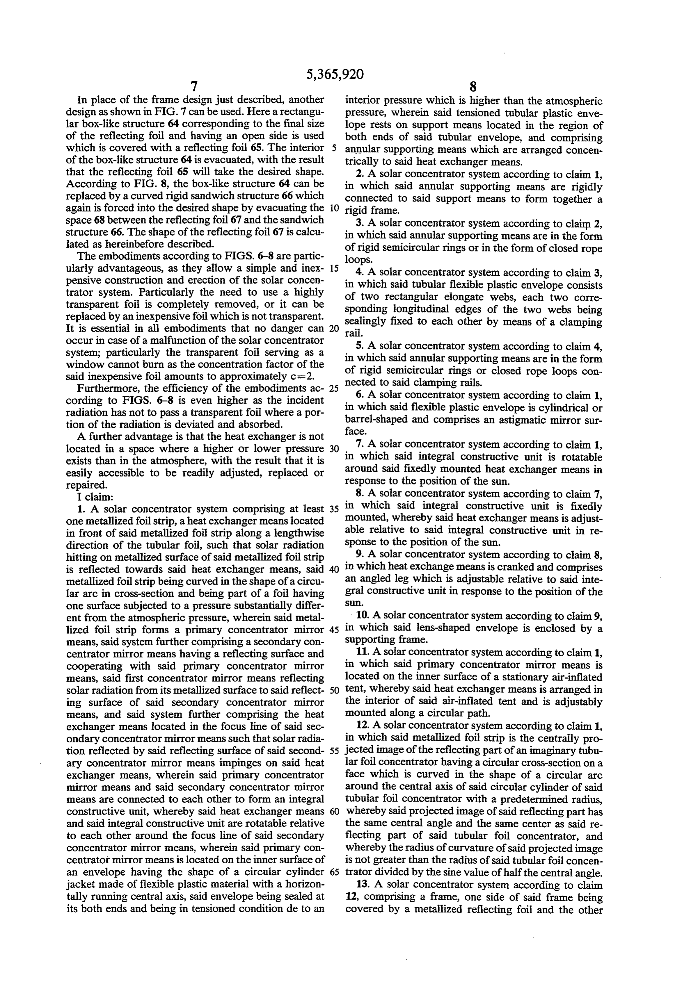
In place of the frame design just described, another interior pressure which is higher than the atmospheric design as shown in FIG. 7 can be used. Here a rectangu pressure, wherein said tensioned tubular plastic enve lar box-like structure 64 corresponding to the final size lope rests on support means located in the region of of the reflecting foil and having an open side is used both ends of said tubular envelope, and comprising which is covered with a reflecting foil 65. The interior annular supporting means which are arranged concen of the box-like structure 64 is evacuated, with the result trically to said heat exchanger means. that the reflecting foil 65 will take the desired shape. 2. A Solar concentrator system according to claim 1, According to FIG. 8, the box-like structure 64 can be in which said annular supporting means are rigidly replaced by a curved rigid sandwich structure 66 which connected to said support means to form together a again is forced into the desired shape by evacuating the 10 rigid frame.
space 68 between the reflecting foil 67 and the sandwich 3. A solar concentrator system according to claim 2, structure 66. The shape of the reflecting foil 67 is calcu in which said annular supporting means are in the form lated as hereinbefore described.
The embodiments according to FIGS. 6-8 are partic of rigid semicircular rings or in the form of closed rope loops.
ularly advantageous, as they allow a simple and inex 15 4. A solar concentrator system according to claim 3, pensive construction and erection of the solar concen trator system. Particularly the need to use a highly in of which said tubular flexible plastic envelope consists two rectangular elongate webs, each two corre transparent foil is completely removed, or it can be sponding longitudinal edges of the two webs being replaced by an inexpensive foil which is not transparent. sealingly fixed to each other by means of a clamping It is essential in all embodiments that no danger can 20 rail.
occur in case of a malfunction of the solar concentrator system; particularly the transparent foil serving as a in 5.which
A Solar concentrator system according to claim 4, said annular supporting means are in the form window cannot burn as the concentration factor of the said inexpensive foil amounts to approximately c=2. of rigid semicircular rings or closed rope loops con Furthermore, the efficiency of the embodiments ac nected 25 to said clamping rails.
cording to FIGS. 6-8 is even higher as the incident in whichsolar 6. A concentrator system according to claim 1, radiation has not to pass a transparent foil where a por barrel-shaped flexible said plastic envelope is cylindrical or and comprises an astigmatic mirror sur tion of the radiation is deviated and absorbed.
A further advantage is that the heat exchanger is not face.
located in a space where a higher or lower pressure 30 7. A Solar concentrator system according to claim 1, exists than in the atmosphere, with the result that it is in which said integral constructive unit is rotatable easily accessible to be readily adjusted, replaced or around said fixedly mounted heat exchanger means in repaired. response to the position of the sun. I claim: 8. A solar concentrator system according to claim 7, 1. A solar concentrator system comprising at least 35 in which said integral constructive unit is fixedly one metallized foil strip, aheat exchanger means located mounted, whereby said heat exchanger means is adjust in front of said metallized foil strip along a lengthwise able relative to said integral constructive unit in re direction of the tubular foil, such that solar radiation sponse to the position of the sun. hitting on metallized surface of said metallized foil strip 9. A solar concentrator system according to claim 8, is reflected towards said heat exchanger means, said in which heat exchange means is cranked and comprises metallized foil strip being curved in the shape of a circu an angled leg which is adjustable relative to said inte lar arc in cross-section and being part of a foil having gral constructive unit in response to the position of the one surface subjected to a pressure substantially differ S.
ent from the atmospheric pressure, wherein said metal 10. A solar concentrator system according to claim 9, lized foil strip forms a primary concentrator mirror 45 in which said lens-shaped envelope is enclosed by a means, said system further comprising a secondary con supporting frame.
centrator mirror means having a reflecting surface and 11. A Solar concentrator system according to claim 1, cooperating with said primary concentrator mirror in which said primary concentrator mirror means is means, said first concentrator mirror means reflecting located on the inner surface of a stationary air-inflated solar radiation from its metallized surface to said reflect 50 tent, whereby said heat exchanger means is arranged in ing surface of said secondary concentrator mirror the interior of said air-inflated tent and is adjustably means, and said system further comprising the heat mounted along a circular path.
exchanger means located in the focus line of said sec 12. A solar concentrator system according to claim 1, ondary concentrator mirror means such that solar radia in which said metallized foil strip is the centrally pro tion reflected by said reflecting surface of said second 55 jected image of the reflecting part of an imaginary tubu ary concentrator mirror means impinges on said heat lar foil concentrator having a circular cross-section on a exchanger means, wherein said primary concentrator face which is curved in the shape of a circular arc mirror means and said secondary concentrator mirror around the central axis of said circular cylinder of said means are connected to each other to form an integral tubular foil concentrator with a predetermined radius, constructive unit, whereby said heat exchanger means whereby said projected image of said reflecting part has and said integral constructive unit are rotatable relative the same central angle and the same center as said re to each other around the focus line of said secondary flecting part of said tubular foil concentrator, and concentrator mirror means, wherein said primary con whereby the radius of curvature of said projected image centrator mirror means is located on the inner surface of is not greater than the radius of said tubular foil concen an envelope having the shape of a circular cylinder 65 trator divided by the sine value of half the central angle. jacket made of flexible plastic material with a horizon 13. A solar concentrator system according to claim tally running central axis, said envelope being sealed at 12, comprising a frame, one side of said frame being its both ends and being in tensioned condition de to an covered by a metallized reflecting foil and the other
Page 10
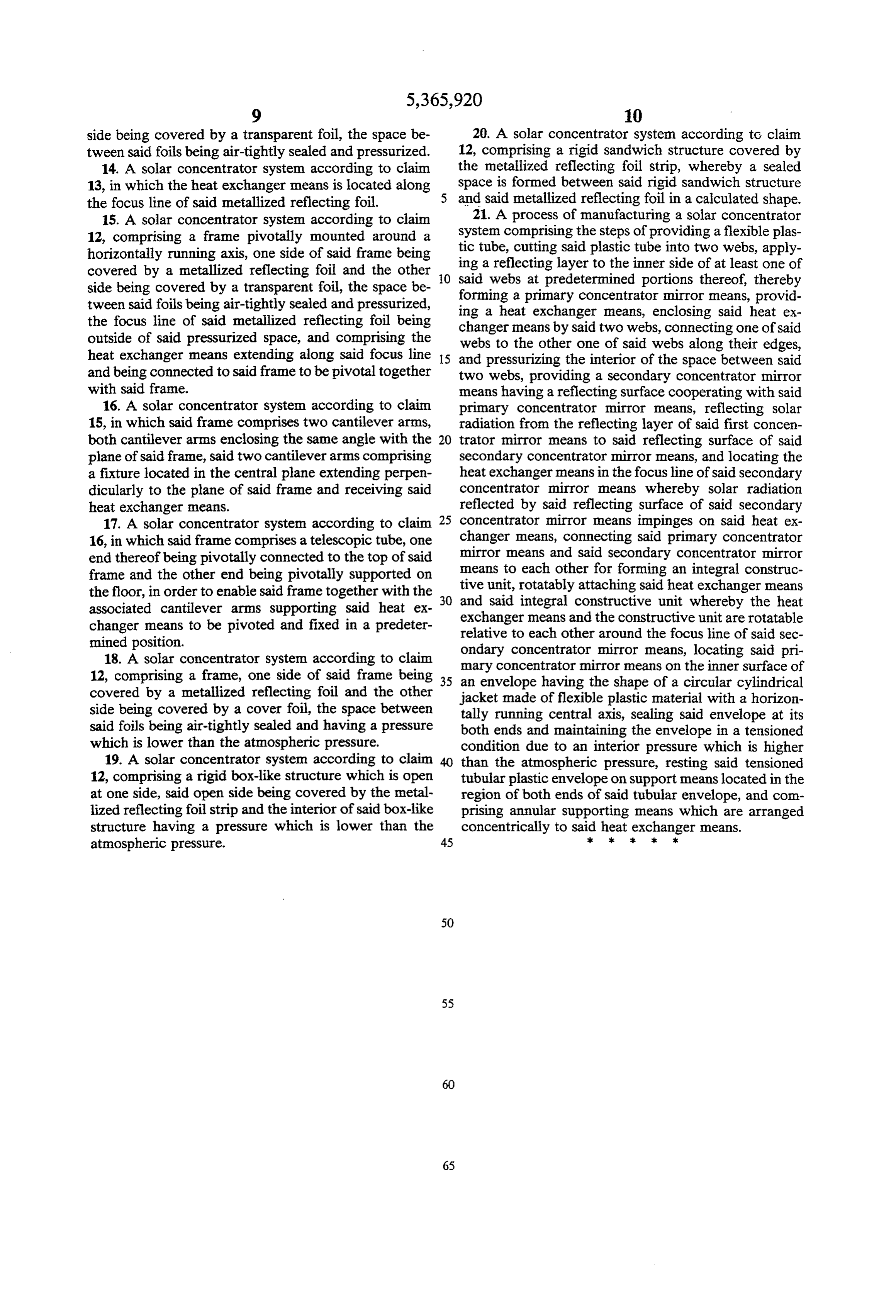
side being covered by a transparent foil, the space be 20. A solar concentrator system according to claim tween said foils being air-tightly sealed and pressurized. 12, comprising a rigid sandwich structure covered by 14. A solar concentrator system according to claim the metallized reflecting foil strip, whereby a sealed 13, in which the heat exchanger means is located along space is formed between said rigid sandwich structure the focus line of said metallized reflecting foil. and said metallized reflecting foil in a calculated shape. 15. A solar concentrator system according to claim 21. A process of manufacturing a solar concentrator 12, comprising a frame pivotally mounted around a system comprising the steps of providing a flexible plas horizontally running axis, one side of said frame being ing tic tube, cutting said plastic tube into two webs, apply covered by a metallized reflecting foil and the other O saidawebs reflecting layer to the inner side of at least one of at predetermined portions thereof, thereby side being covered by a transparent foil, the space be forming a primary concentrator mirror means, provid tween said foils being air-tightly sealed and pressurized, ing a heat exchanger means, enclosing said heat ex the focus line of said metallized reflecting foil being changer means by said two webs, connecting one of said outside of said pressurized space, and comprising the webs to the other one of said heat exchanger means extending along said focus line 15 and pressurizing the interior ofwebs along their edges, the space between said and being connected to said frame to be pivotal together two webs, providing a secondary concentrator mirror with said frame. means having a reflecting surface cooperating with said 16. A solar concentrator system according to claim primary concentrator mirror means, reflecting solar 15, in which said frame comprises two cantilever arms, radiation from the reflecting layer of said first concen both cantilever arms enclosing the same angle with the trator mirror means to said reflecting surface of said plane of said frame, said two cantilever arms comprising secondary concentrator mirror means, and locating the a fixture located in the central plane extending perpen heat exchanger means in the focus line of said secondary dicularly to the plane of said frame and receiving said concentrator mirror means whereby solar radiation heat exchanger means. reflected by said reflecting surface of said secondary 17. A solar concentrator system according to claim 25 concentrator mirror means impinges on said heat ex 16, in which said frame comprises a telescopic tube, one changer means, connecting said primary concentrator end thereof being pivotally connected to the top of said mirror means and said secondary concentrator mirror frame and the other end being pivotally supported on means to each other for forming an integral construc the floor, in order to enable said frame together with the 30 tive unit, rotatably attaching said heat exchanger means and said integral constructive unit whereby the heat associated cantilever arms supporting said heat ex exchanger means and the constructive unit are rotatable changer means to be pivoted and fixed in a predeter relative to each other around the focus line of said sec mined position.
18. A solar concentrator system according to claim ondary concentrator mirror means, locating said pri 12, comprising a frame, one side of said frame being 35 an envelope havingmirror mary concentrator means on the inner surface of the shape of a circular cylindrical covered by a metallized reflecting foil and the other jacket made of flexible plastic material with a horizon side being covered by a cover foil, the space between tally running central axis, sealing said envelope at its said foils being air-tightly sealed and having a pressure both ends and maintaining the envelope in a tensioned which is lower than the atmospheric pressure. condition due to an interior pressure which is higher 19. A solar concentrator system according to claim than the atmospheric pressure, resting said tensioned 12, comprising a rigid box-like structure which is open tubular plastic envelope on support means located in the at one side, said open side being covered by the metal region of both ends of said tubular envelope, and com lized reflecting foil strip and the interior of said box-like prising annular supporting means which are arranged structure having a pressure which is lower than the concentrically to said heat exchanger means. atmospheric pressure. 45 sk s:
Provenance
- Collection
- Cited prior art
- Original PDF
- patentimages.storage.googleapis.com →
- Filed
- 1990-02-21
- Pages
- 10
- Method
- pdftotext (the PDF's own text layer) + pdftoppm 300dpi page scans
- Source
- Google Patents bibliographic record
- Granted
- 1994-11-22
- Inventors
- Rudolf Lechner; Bomin Solar GmbH and Co KG
- Transcribed from
- patentimages.storage.googleapis.com →