patent · US5090399
Solar cooker with a parabolic reflector
25 February 1992
Page 1 — bibliographic record
United States Patent (19) 11 Patent Number: 5,090,399 Tarcici (45) Date of Patent: Feb. 25, 1992 (54) SOLAR COOKER WITH A PARABOLIC 4, 12,97 9/1978 Lang ................................... 26/45 REFLECTOR FOREIGN PATENT DOCUMENTS (76) Inventor: Adnan Tarcici, 8 R. Des Bugnons, 598.555 4/1978 Switzerland ....................... 126/451 Geneva, Switzerland, 1217 21 Appl. No.: 673,147 Primary Examiner-James C. Yeung
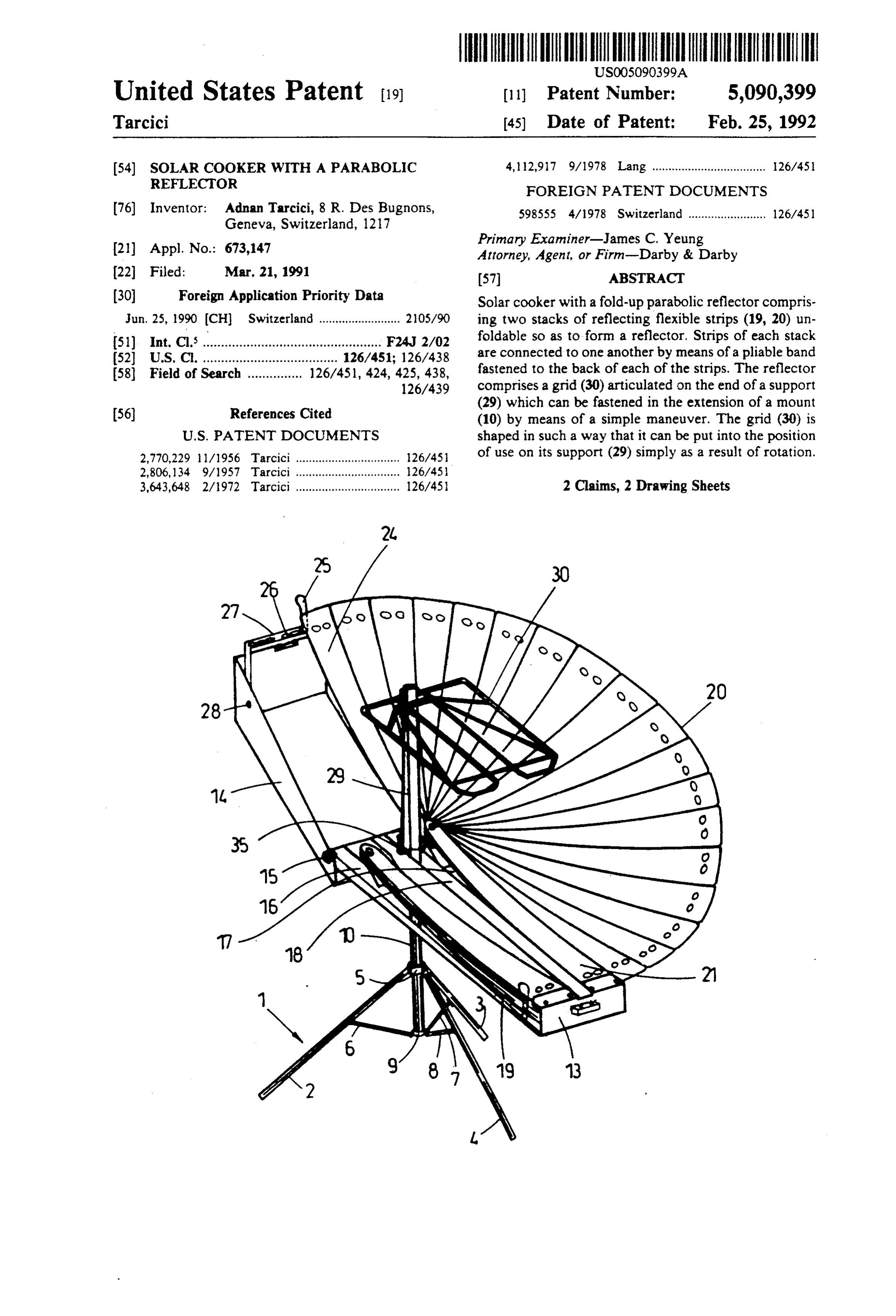
Attorney, Agent, or Firm-Darby & Darby 22 Filed: Mar. 21, 1991 (57) ABSTRACT (30) Foreign Application Priority Data Solar cooker with a fold-up parabolic reflector compris Jun. 25, 1990 (CH) Switzerland ......................... 205/90 ing two stacks of reflecting flexible strips (19, 20) un (51) Int. Cl* ............................................ F24, 2/02 foldable so as to form a reflector. Strips of each stack 52 U.S. C. ..................................... 126/451; 126/438 are connected to one another by means of a pliable band 58) Field of Search ............... 126/45, 424, 425, 438, fastened to the back of each of the strips. The reflector 126/439 comprises a grid (30) articulated on the end of a support
(29) which can be fastened in the extension of a mount (10) by means of a simple maneuver. The grid (30) is
2,770,229 /1956 Tarcici ................................ 26/45 of use on its support (29) simply as a result of rotation. 2,806, l34 9/1957 Tarcici ................................ 26/45 3,643,648 2/1972 Tarcici ................................ 126/45 2 Claims, 2 Drawing Sheets
Page 2
Drawing sheet — no readable text.
Page 3
Drawing sheet — no readable text.
Page 4
SOLAR COOKER WITH A PARABOLEC BRIEF DESCRIPTION OF THE DRAWINGS REFLECTOR The accompanying drawing illustrates an embodi ment of the invention by way of example.
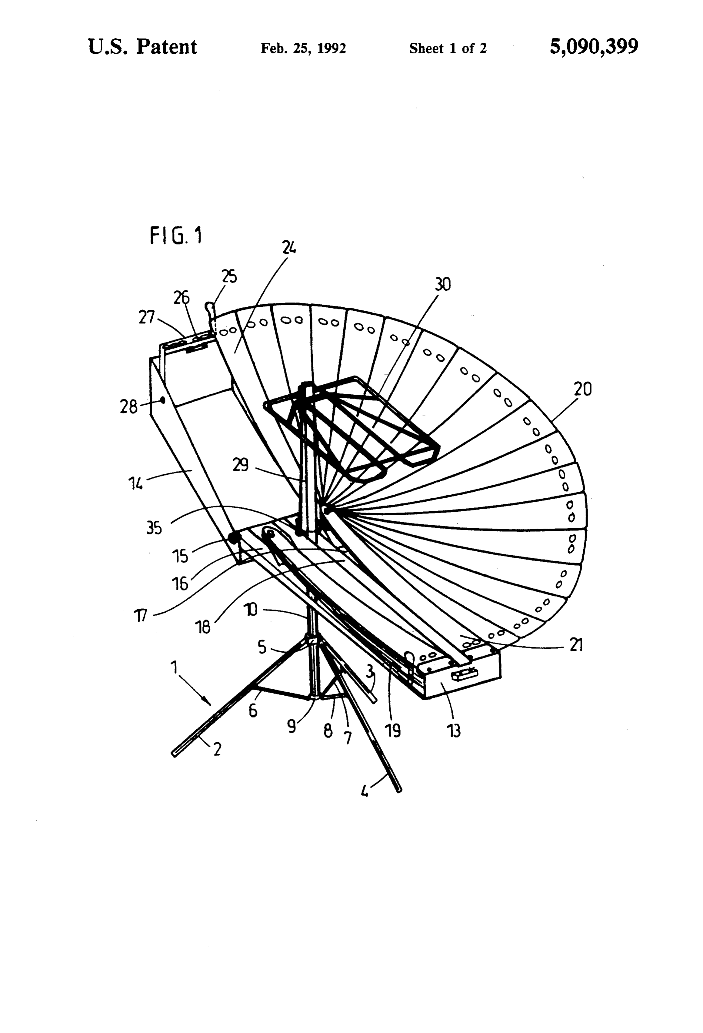
FIELD OF THE INVENTION FIG. shows an unfolded solar cooker with a semi parabola unfolded.
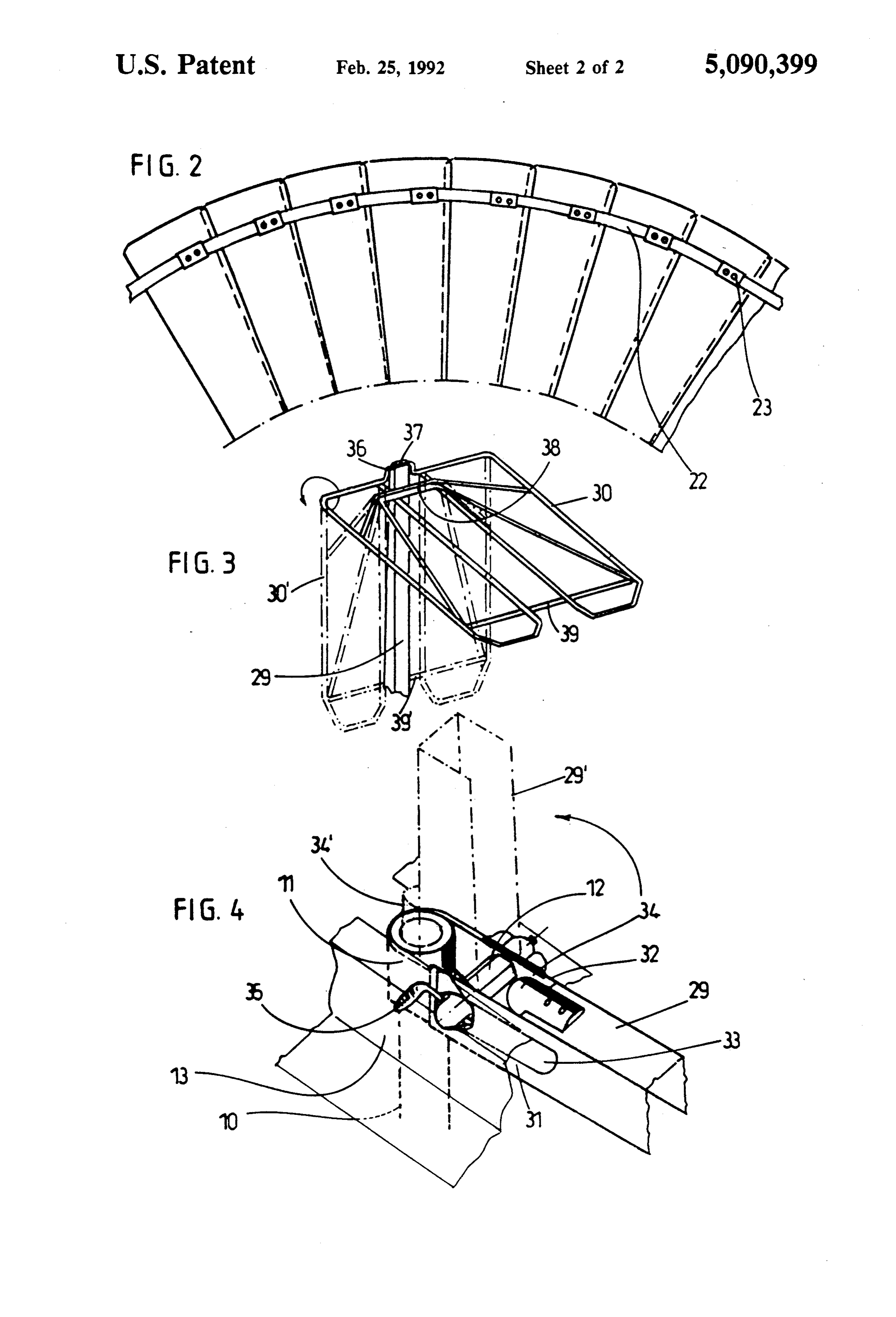
The present invention relates to a solar cooker with a FIG. 2 is a detailed bottom view of some of the re fold-up parabolic reflector. flecting strips of a stack of strips. PRIOR ART FIG. 3 is a detailed view of the grid on its support.
O FIG. 4 is a detailed view of the articulation and fas
Such solar cookers are known from U.S. Pat. Nos. tening of the grid support on the mount of the solar 2,760,482, 2,770,229, 2,806,134, 3,643,648 and 3,797,476 cooker.
in the Applicant's name. These solar cookers constitute DESCRIPTION OF THE PREFERRED a continuous development of the product which is in EMBODIMENT tended to make it more efficient and more practical to 15 use. U.S. Pat. No. 3,643,648 describes an especially The solar cooker illustrated in FIG. 1 comprises a elaborate embodiment comprising a mount which can mount 1 consisting of three legs 2, 3, 4, the upper ends be turned down into the space of a two-part housing of which are articulated on a ring 5 and an intermediate containing two stacks of reflecting flexible strips which 20 point of which is connected to a second ring 9 by means can be unfolded adjustably to form a parabolic reflector of articulated bars 6, 7, 8, the lower ring 9 supporting a focusing the solar radiation on a grid fastened to a sup guided bytube vertical 10 mounted rotatably on the ring 9 and port which can likewise be turned down into the vol means of athe upper ring 5 retained on the tube 10 by ume of the housing. In this embodiment, the strips are its upper end, with Thecirclip. vertical tube 10 is equipped, at a U-shaped piece 11 forming a dou connected to one another by means of two pliable bands 25 ble bracket for an axle 12 (FIG. 4), about which is artic passing through the strips via slots which allow the ulated a first part 13 of an elongate rectangular housing strips to shift on the bands, this shift being liable to cause consisting of the first part 13 and the second part 14 a maladjustment of the relative position of the strips. On articulated at 15 on a small side of the part 13 of the the other hand, the support of the grid is not held verti housing.
cally in a reliable way and the fastening of the grid in 30 The first part 13 of the housing is divided into two the horizontal position requires the tightening of a compartments 16 and 17 extending parallel to the long screw which also has to be slackened in order to fold up side of the housing, these two compartments 16 and 17 the solar cooker. being separated by a space 18, in which the mount 1 is accommodated in the turned-down and folded-up posi
SUMMARY OF THE INVENTION 35 tion. Each of the compartments 16 and 17 of the hous The object of the present invention is to overcome ing contains a stack of reflecting flexible strips 19 and these disadvantages. 20, each of these stacks forming a fan, the stack 19 being According to a main aspect of the invention, the unfoldedin position.
shown the folded-up position and the stack 20 in the
The upper strip 21 of each stack is reflecting strips of the solar cooker, which are arranged fastened as two stacks in two compartments of one part of the All the strips of a stacktoare permanently the first part 13 of the housing.
connected to one another by housing, are connected to one another by means of a means of a nonelastic pliable pliable band fastened to the lower face of each of the under each strip at a point 23band 22 (FIG. 2) fastened strips at a point near that side of the strips facing the facing the middle space 18 when thethat near side of the strip strips are folded up other stack of strips, the upper strip of each stack being in the form of stacks in the housing. The lower strip 24 fastened to the housing, and the lower strip being of each stack is equipped with a grasping means 25 equipped with grasping and catching means for fasten terminating in a tab intended, in the unfolded position of ing it to the other part of the housing, in the unfolded the strips, for engaging into one of the holes 26 of a position, and the support of the grid is articulated on the stirrup 27 mounted near the end of the second part of mount and, at its base, has two parallel wings equipped the housing 14 opposite the point of articulation 15 so with slots, through which passes a horizontal axle fixed that it can be turned down about an axle 28. The row of to the mount and to a part laterally offset relative to said holes 26 makes it possible to adjust the position of the slots and intended for engaging vertically into the focal points of the two parabolic half-reflectors formed mount in the vertical position of said support, the slots by the two stacks of strips, as described in U.S. Pat. No. 3,643,648. Since the reflecting strips are fastened to the of which slide on said axle, the grid being articulated on 55 band the end of the support by means of an angled part com 22, their unfolded position is fixed and foolproof. prising an axle for pivoting on the support and a part 29 carrying The solar cooker comprises, furthermore, a support parallel to this axle, but at a horizontal and vertical utensil. Theasupport grid 30 intended for supporting a cooking 29 consists of a U-shaped section, distance from this axle, such that it comes up against the the lower part of which forms two wings 31 and 32, support in the horizontal position of the grid, thereby each having a slot 33 through which the axle 12 passes. maintaining the grid in this position. A cylindrical piece 34 is fastened to the transverse wall As a result of these improvements, the solar cooker of the section forming the support 29. This piece 34 can be unfolded into the operational position in an in therefore extends between the wings 31 and 32 so as to stant, the only locking operation involving locking the 65 be offset radially relative to the slots 33. In FIG. 4, the housing in the appropriate position about its horizontal support 29, as represented by unbroken lines, is in a free axle on the mount. The solar cooker is likewise folded position allowing it to pivot about the axle 12 for turn up very quickly with a minimum of manipulations. ing it down and stowing it in the space 18 of the hous
Page 5
ing. From this position, the support 29 can be pivoted in about said longitudinal axis of said mount and for the direction of the arrow in order to bring it into a pivoting about an axis transverse to said longitudi vertical position, as represented by dot-and-dash lines nal axis, said first part being longitudinally divided 29'. In this position, the cylindrical piece 34 is in axial into a first compartment and a second compart alignment with the tube 10 of the mount, and its diame- 5 ment, said compartments having a space between ter is such that it can engage freely into the tube 10, as them, said space being dimensioned to receive said shown at 34". This engagement is allowed by the slots mount in a folded condition of said mount; 33. In this position, the support 29 is fastened vertically, a first stack and a second stack of reflecting strips, the axle 12 and the slots 33 contributing to the firmness each said stack being located in a respective one of of this vertical fastening. To fold up the support 29, it is 10 said compartments, the strips in each said stack sufficient to pull it upwards slightly in order to free it being connected to each other at one end by a from the tube 10 and turn it down into the housing. common pivot for reversible unfolding of said The axle 12 possesses, furthermore, bearing surfaces, strips about said pivot to form a portion of a para against which it is possible to lock the first part 13 of the bolic reflector, the reflector portions produced by housing by means of a handle 35 equipped with an ec- 15 each said stack together forming a parabolic reflec centric forming a clamping cam. Such a device is well tor, the pivoted strip ends being proximate said known per se. mount, the other ends of said strips of each said The grid 30 is articulated on the end of the support 29 stack being connected each to the adjacent strip by by means of an angled part comprising a bent part 36 a pliable band, a first strip of each said stack being forming a pivot axle mounted rotatably in a receptacle 20 fixed to said housing and a last strip of each said. formed at the end of the support 29 by the folding up of stack having means for connection to said second a lip 37 and by a part 38 parallel to the axle 36, but part when said reflector is unfolded; located at some horizontal and vertical distance from this axle 36, in such a way that, in the horizontal posi adjustable means for connection of said last said strips tion of the grid 30, the part 38 comes up against the 25 to said second part, said adjustable means being support 29, thereby maintaining the grid 30 in this hori fastened to said second part of the housing at the zontal position. To fold up the grid, it is sufficient to end of said second part away from said mount; pivot it in the direction of the arrow in order to bring it a support having at one end a bracket including two into the position represented by dot-and-dash lines 30'. wings extending in parallel, said wings having par The turning down is limited by the bar 39 of the grid 30 allel slots, said support having an engagement which comes up against the support 29. Conversely, the member attached between said wings for engaging unfolding of the grid 30 for putting it into the opera said mount when said support is unfolded, in use, tional position takes place simply as a result of the rota relative to said mount;
tion of the latter in the opposite direction. an axle passing through said slots with sliding and Starting from the unfolded position shown in FIG. 1, 35 pivoting engagement, said support being articu to fold up the solar cooker it is sufficient to release the lated relative to said mount by said axle; fastening 25, fold up the strips into the part 13 of the a grid for supporting a utensil to be heated at the focal housing, turn down the grid 30 rearwards, pull slightly point of the reflector, said grid being pivotably on the support 29 and turn it down into the space 18, connected to said support at the end of said support fold up the legs of the mount and turn down this 40 away from said axle by a first member extended mount into this same space 18, and reclose the housing. along a grid axis and a second member of said grid One of the legs of the mount engages into the U-shaped parallel to said grid axis and said axle, said second section of the support 29. member abutting said support when said support The operations in reverse order are carried out just as and grid are positioned for operation of said reflec quickly for unfolding the solar cooker and putting it 45 tor, said grid being maintained in position by said into the operational position. second member.
I claim: 2. A solar cooker as in claim 1, wherein said mount 1. A solar cooker with a foldable parabolic reflector, includes a rotatable tube aligned to said longitudinal comprising: axis, said bracket being fixed to said tube, said first hous a foldable mount having a longitudinal axis: 50 ing part being mounted to said axle for said transverse a generally hollow rectangular housing of extended pivoting of said housing, and said first housing being length including a first part and a second part, said pivotable about said longitudinal axis by rotation of said parts dividing said housing lengthwise, said hous tube, ing parts being articulated to each other at a pivot and further comprising means for releasably locking axis at one end respectively of said parts, said first 55 said housing for rotation on said axle. part being connected to said mount for rotation
Provenance
- Collection
- Cited prior art
- Original PDF
- patentimages.storage.googleapis.com →
- Filed
- 1991-03-21
- Pages
- 5
- Method
- pdftotext (the PDF's own text layer) + pdftoppm 300dpi page scans
- Source
- Google Patents bibliographic record
- Granted
- 1992-02-25
- Inventors
- Adnan Tarcici
- Transcribed from
- patentimages.storage.googleapis.com →