patent · US2098629
Production of gas and combustion thereof
9 November 1937
Page 1
Drawing sheet — no readable text.
Page 2
Patented Nov. 9, 1937 2,098,629
UNITED STATES PATENT office
PRODUCTION OF GAS AND COMBUSTION
THEREOF
Archer E. Knowlton, Short Beach, Conn.
Application June 13, 1935, Serial No. 26,495
The invention relates to separating water into ly filled with water at the beginning of the op its component gases and subsequently recombin eration.
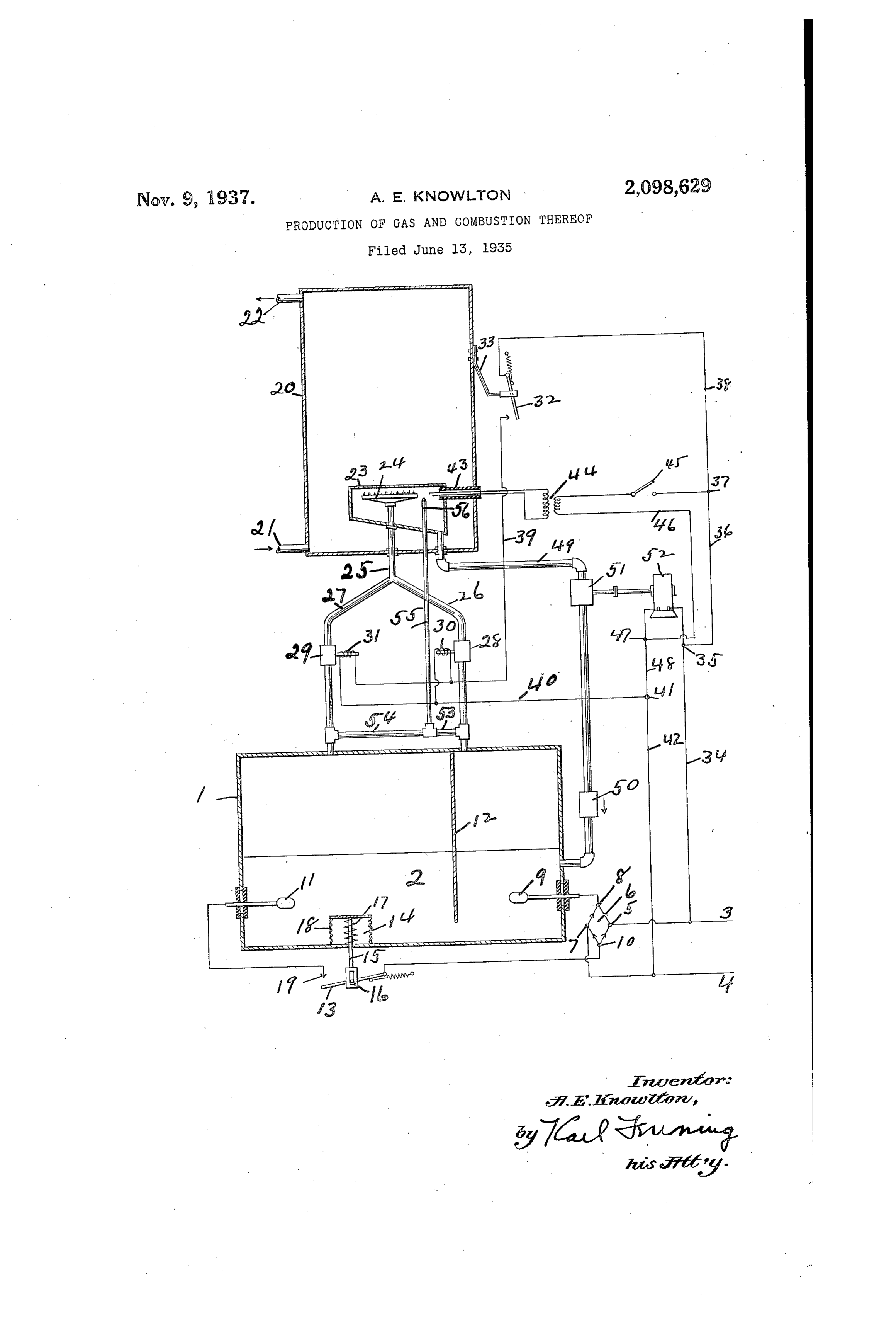
ing the gases into water and utilizing the heat Electrical conductors 3 and 4 may be employed generated by the combining combustion. to bring electricity to the apparatus. The cur 5 It is well known that when a continuous elec rent introduced by the conductors 3 and 4 may trical current is passed through water it will be be direct or alternating current. In the draw electrolyzed and will be separated into hydrogen ing it is assumed that alternating current is and oxygen, one gas coming off at one electrolytic Supplied. The conductor 3 is connected at 5 to a pole and the other gas coming off at the other 0 electrolytic pole. The gases so produced may be rectifier 6 and the conductor 4 is connected at to the rectifier 6. On its direct current side 0.
Stored together or separately and subsequently the rectifier 6 is connected at 8 to an electrode brought together in proper proportions and 9 in the water 2 in the tank and at to it is ignited and burned. The ignition and combus connected to an electrode i? also in the water tion liberates a large amount of heat. Water is 2 in the tank . A partition f2 is illustrated the Sole product of the combustion process and extending across the tank between the elec 5 the water produced by the combustion may be trodes 9 and fl. The partition 2 extends down returned to the original body of water. By this Ward from the top of the tank but stops short means it is possible when operating in a closed of the bottom of the tank so that the water System to repeatedly use a single quantity of wa may seek its level across the tank. Between the 20 ter which is not decreased or increased. Such a contact 0 and electrode f is shown a toggle 20 System may be sealed and aside from unusual Switch arm 3 controlled by a pressure-respon or unexpected leaks may continue to operate sive device 4 here shown as in the water 2 in without additions and without attention for con the tank . Any suitable pressure mechanism siderable periods, may be employed. The device illustrated com The present invention contemplates the em prises a rod f5 engaging the lever 3 by a slot 25 ployment of such operation for the production and pin mechanism 6. Around the stem or rod of useful Work or desirable results. 5 is a coil spring 7 which tends to expand a Warious control mechanisms may be associated metallic bellows 8 and hold the lever f3 against with the apparatus so as to produce a mechanism the contact 9 so as to make electrical connec 30 which , will have its operation initiated and tion between the electrode and the contact 30 Stopped at appropriate times. This may be done ?o of the rectifier 6. When the switch is closed automatically or manually or partially automat current passes between the electrodes 9 and , ically or partially manually. through the water 2 and electrolyzes or decom The specific purpose to which the invention is poses the water. When it is desired to keep the devoted and the useful end in view is not con gases Separate Some Such device as the baffle 2 35 fined to a single operation. The heat of the may be employed although this separation is not combustion may be used for many purposes. A essential. Oxygen is freed at the electrode 9 closed system is not essential but may have ad and collects under pressure above the water in vantages. To illustrate a specific application of the upper portion of the tank to the right of 40 the invention there is here shown and described the partition 2. Hydrogen is freed at the elec 40 an embodiment of a closed system constituting a trode and collects under pressure above the means for heating Water in a tank, which water Water at the upper portion of the tank to the may be used for any suitable or desired purpose. left of the partition, 2. Since twice as much Said storage of combustible gases without loss hydrogen is produced as oxygen it is preferable 45 for Subsequent combustion when heat is desired to have the partition 2 so placed as to leave 45 averts the dissipation through insulation of the twice as much space at the left as at the right. heat from masses which it is desired to main The gases as freed are at more than atmospheric tain in a heated state for extraction at intermit pressure and as the pressure of the accumulated tent intervais. freed gases builds up it tends to cause the nine 50 In the accompanying drawing is shown in tallic bellows 8 to collapse and thus forces open 50 somewhat diagrammatic form apparatus for car the switch lever 3 against the pressure of the rying out the invention. spring 7. Thus the electrolytic decomposing A tank f is provided which is partially filled of the Water is Stopped. When Sufficient gas has with water 2. The amount of water in the tank assembled under pressure to the point for which 55 is immaterial although if desired it may be near the apparatus may be set. The reservoir of gas 55
Page 3
and the pressure may be fixed at any practical combustion until ignition initiates it. By closing Switch 45 the pilot fame can be ignited and will limits as controlled by the character of the tank then continue burning indefinitely or until it is and other parts subjected to the pressure.
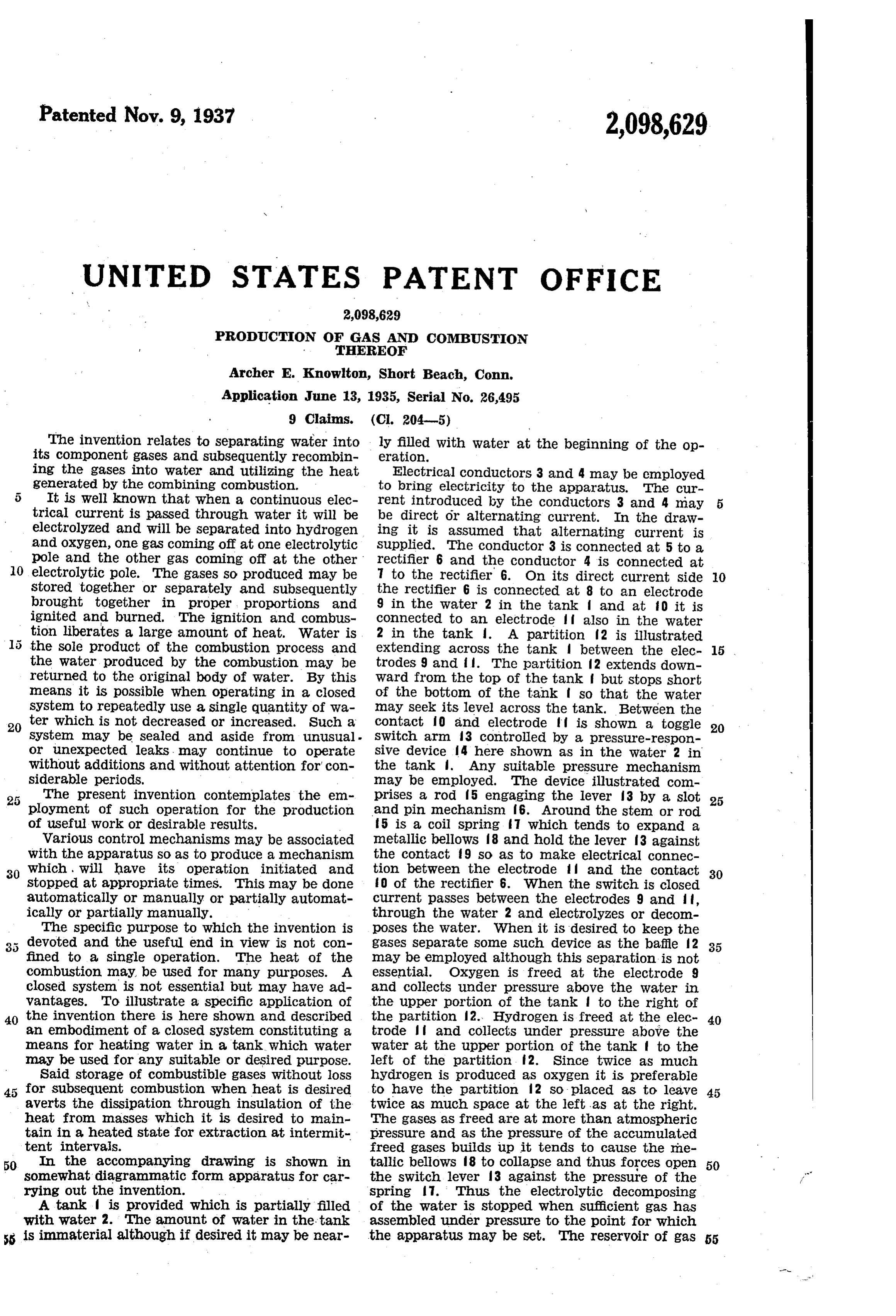
Associated with the tank is a tank 20 shown purposely extinguished. The flame can be re started at any time by closing the switch 45. In aS provided at its botton with an inlet pipe 2 the initial condition of the operating cycle the and at its top an outlet pipe 22. Suitable valves, Water in the tank 20 will be cold and the thermo not shown, may be associated with the pipes 2 strip 33 will allow the switch 32 to be closed. This and 22 so as to allow water to enter the tank 20 and to be withdrawn therefrom. Within the tank Will cause the valves 28 and 29 to be opened al O 20 is a closed chamber 23 which may be referred lowing hydrogen and oxygen to pass to the burner 10 to as a bomb. Within the chamber 23 is a burner 24. The pilot burner 56 being lighted, the gases 24 to which leads a pipe 25 to which are joined in the burner 24 will be ignited. As the combus pipes 26 and 27. The pipe 26 leads from the upper tion proceeds the water in the tank 20 may be portion of the tank I at the right of the parti come heated and the thermo-couple 33 will cause 15 tion 2 and thus may conduct oxygen to the burn the Switch 32 to be expanded as illustrated in the er 24. The pipe 21 leads from the upper por drawing. This will deemergize the Solenoids 30 tion of the tank at the left of the partition 2 and 3 to allow the valves 28 and 29 to be closed and thus may conduct hydrogen to the burner 24. causing the ignition in the burner 24 to cease. The pipes 26 and 2 are diagrammatically illus When the heated water is withdrawn from the 20 trated by similar lines. It may be desirable, how tank 20 or when the water in the tank 20 becomes ever, to have the pipe 2 twice as large as the pipe cold the Switch 32 may close and again start the 26 so as to bring the gases in proper proportions ignition. As it is formed the product of the com to the pipe 25 and thus to the burner 24. In the , bustion at the burner 24 condenses into water pipe 26 is a valve 28 and in the pipe 27 is a similar in the bomb 23 and is withdrawn through the pipe valve 29. The valve 28 is illustrated as controlled 29 and returned to the water 2 in the tank . by a solenoid 30. The valve 29 is illustrated as The electrodes 9 and cause water to be sepa controlled by a solenoid 3. The solenoids 30 and rated from the hydrogen and oxygen, until suffi cient of the gas is stored in the upper part of the 3 are connected in parallel to a circuit which is tank to increase the pressure sufficiently to controlled by the toggle Switch lever 32. The cause the Switch 3 to open when the electroly 30 Switch 32 is controlled by a thermostatic device
Such as the bi-metallic strip 33 fastened to one sis will be discontinued until sufficient gas has side of the tank 20. The current for the solenoids been withdrawn to the burner 24 to reduce the pressure Sufficiently to allow the Spring to close 30 and 3 may be traced from the conductor 3 through the conductor 34 to the contact point 35 the Switch 3 and again initiate the electrolytic 35 through the conductor 36 past the contact point action. The gases are thus stored up for use as 35 may be needed for the sake of the heat to be 37 through the conductor 38 to the switch lever derived 32 through the conductor 39 through the sole from their combustion.
noids 30 and 3 through the conductor 40 to the Warious changes in structure and operation in contact point 4 and through the conductor 42 to the illustrative apparatus may be made in carry 40 40 the conductor 4. Extending through the wall of ing out the invention. the tank 20 and into the bomb 23 is illustrated an I claim as my invention: insulated ignition plug 43. The ignition plug 43 1. The method of heating fluid comprising is connected to a spark coil 44 controlled by a partiallyin filling with water a tank having elec Switch 45, illustrated as a manually controlled trodes the water and a partition above the
45 Switch leading to the contact point 37 and so to Water and extending thereinto and between the the conductor 3. The other side of the coil 44 electrodes, conducting electricity to the elec leads through the conductor 46 to the contact trodes to Separate the Water into hydrogen and point 47 and thence through the conductors 48 Oxygen, collecting the gases separately on op and 42 to the conductor 4. Leading from the posite sides of the partition, leading the gases 50 bomb 23 is a pipe 49 which may carry the water to a burner within a closed chamber surrounded produced by the combustion of the gases in the by the fluid to be heated, igniting the gases at burner 24 into the water 2 in the tank . In as the burner, Controlling the flow of gases to the much as the gases in the tank may produce con burner in accordance with the heating of the siderable pressure it may be desirable to provide fluid, controlling the flow of electricity to the 5 5 55 a check valve 50 in the pipe 49 which will allow electrodes in accordance with the pressure of water to go toward the tank but not toward the the gases in the tank, and returning the prod bomb 23. As an aid in the flow of the water ucts of the combustion to the tank. through the pipe 49-there may be provided a pump 2. A tank partially filled with water, electrodes 5 which is illustrated as operated by a small elec in the water which when continuous electric 60 60 tric motor 52 connected across the conductors 3 current Apasses between them will break down the water into hydrogen and oxygen, a partition and 4 at the contact points 35 and 47.
Suitable switching mechanism may be provided above the Water and extending thereinto and for this motor 52 and suitable switching mecha between the electrodes, conduits from the spaces abgye 4the water on both sides of the partition, nism may be provided for the conductors 3 and 4 valves in the conduits, Solenoids arranged when 65 as well as for other elements shown.
On the pipe 26 between the valve 28 and the energized to operate the valves, a conduit con tank is a pipe 53. On the pipe 27 between the necting the said conduits, a burner to which the last named conduit extends, a pipe connected valve 29 and the tank f is a pipe 54. The pipes with the spaces on both sides of the partition 70 53 and 54 lead to a pipe 55 extending into the bomb above the water, a pilot light to which the pipe 70 23'and provided with a Small orifice 56 which may act as a permanently burning pilot light for the leads and adjacent the burner, a spark plug ad burner 24. These may be suitably controlled by jacent the pilot light and burner, a closed cham Valves etc. ber surrounding the burner, the pilot light and It will be understood that when initially started the Spark plug, a conduit leading from the closed ?? 75 the gases Will be generated but there will be no chamber to the tank, a pump in the last named
Page 4
conduit, a check valve in the last named con the burner, a closed chamber surrounding the burner and the spark plug, a conduit leading duit, a closed receptacle enclosing the chamber, means for leading fluid to and from the recepta from the closed chamber to the tank, a check cle and into contact with the chamber, means Valve in the last named conduit, a closed recep associated With the receptacle for Operating the tacle enclosing the chamber, and means for lead solenoids in response to the temperature of the ing fluid to and from the receptacle and into receptacle and means associated with the tank contact with the chamber, for controlling electric current between the elec 6. A system of storing and using energy com trodes in response to the pressure within the prising a body of water, means adapted to elec trolyze the Water at a certain rate into its con O
Stituent gases under pressure, means for causing 3. A tank partially filled with water, electrodes said gases to be stored under pressure, means for in the water which when electric current passes between them will break down the water into causing the electrolysis of the water into its gases hydrogen and oxygen, a partition above the wa to be arrested when the stored gases reach a pre 15 ter and extending thereinto and between the determined condition, a combustion chamber, 15 electrodes, conduits from the spaces above the means for causing and permitting Said gases to water on both sides of the partition, valves in burn in said combustion chamber, a body to be the conduits, a conduit connecting the said con heated by the heat of Said combustion, means duits, a burner to which the last named conduit for controlling the burning of said gases in accord 20 extends, a pipe connected with the spaces on with the heat requirements, and means for re 20 both sides of the partition above the water, a turning the products of combustion to the body pilot light to which the pipe leads and adjacent of Water.
the burner, a spark plug adjacent the pilot 7. A System of storing and using energy com light and the burner, a closed chamber surround prising a body of water, means adapted to elec 25 25 ing the burner, the pilot light and the spark trolyze the water into its constituent gases under plug, a conduit leading from the closed chamber pressure at a substantially constant rate over to the tank, a pump in the last named conduit, relatively long periods, means for causing said gases to be stored under pressure, means for a check valve in the last named conduit, a closed causing receptacle enclosing the chamber, means for the electrolysis of the Water into its gases 30 30 leading fluid to and from the receptacle and into to be arrested when the stored gases reach a contact with the chamber, means associated with predetermined condition, a combustion chamber, the receptacle for operating the valves in re means for causing and permitting said gases to Sponse to the temperature of the receptacle, and burn in Said combustion chamber at a relatively means associated with the tank for controlling high rate during relatively short periods, a body 35 electrical current between the electrodes in re to be heated by the heat of said combustion, 35 Sponse to the pressure within the tank. means for controlling the burning of said gases 4. A tank partially filled with Water, electrodes in accord With the heat requirement, and means in the water which when continuous electric cur for returning the products of combustion to the rent passes between them will break down the body of water. ? 40 water into hydrogen and oxygen, storage means 8. A system of storing and using energy com 40 above the water, conduits from the storage prising a body of Water, means adapted to elec means, valves in the conduits, solenoids arranged. trolyze the water at a certain rate into its con When energized to operate the valves, a conduit stituent gases under pressure, means for causing Connecting the said conduits, a burner to which said gases to be stored under pressure, means for 45 the last named conduit leads, a spark plug ad causing the electrolysis of the Water into its gases jacent the burner, a closed chamber surround to be arrested. When the stored gases reach a pre ing the burner and the spark plug, a conduit determined condition, a combustion chamber, leading from the closed chamber to the tank, a means for causing and permitting Said gases to check valve in the last named conduit, a closed burn in said combustion chamber, a body to be 50 receptacle enclosing the chamber, means for for heated by the heat of Said combustion, means leading fluid to and from the receptacle and into controlling the time and intensity and dura contact with the chamber, means associated with tion of Said combustion in accord with the heat the receptacle for operating the valves in re requirements, and means for returning the prod Sponse to the temperature of the receptacle, and ucts of combustion to the body of Water. 5 5 means associated with the tank for controlling 9. A method of heating a fluid comprising sub 55 electrical current between the electrodes in re jecting a body of water to electrolysis to produce Sponse to the pressure within the tank. oxygen and hydrogen under pressure, maintain 5. A tank partially filled with water, electrodes ing the gases under the generated pressure, gen in the Water which when continuous current erating further gases in response to diminution 60 60 passes between them will break down the water of gas pressure below a predetermined minimum, into hydrogen and oxygen, storage means above combining and igniting the gases, transferring the resultant heat to a fluid to be heated, and in the water, conduits from the storage means, terrupting valves in the conduits, solenoids arranged when and initiating the combustion respon energized to operate the valves, a conduit con sive to the condition of the fluid to be heated. 65 65 necting the said conduits, a burner to which the last named conduit leads, a Spark plug adjacent ARCHER E. KNOWLTON.
Provenance
- Collection
- Cited prior art
- Original PDF
- patentimages.storage.googleapis.com →
- Filed
- 1935-06-13
- Pages
- 4
- Method
- pdftotext (the PDF's own text layer) + pdftoppm 300dpi page scans
- Source
- Google Patents bibliographic record
- Granted
- 1937-11-09
- Inventors
- Archer E Knowlton
- Transcribed from
- patentimages.storage.googleapis.com →