patent · US5238547
Gas-liquid separation device for electroconductive gas-liquid two phase flow
24 August 1993
Page 1 — bibliographic record
United States Patent (19) 11) Patent Number: 5,238,547 Tsubouchi et al. 45 Date of Patent: Aug. 24, 1993 (54) GAS-LIQUID SEPARATION DEVICE FOR Primary Examiner-John Niebling ELECTROCONDUCTIVE GAS-LIQUID TWO Assistant Examiner-William T. Leader PHASE FLOW Attorney, Agent, or Firm-Antonelli, Terry, Stout & Kraus 75 Inventors: Kuniyoshi Tsubouchi, Mito; Tsutomu
Okusawa, Hitachi; Nobuo Hamano, 57 ABSTRACT
Tokyo, all of Japan
A gas-liquid separation method for electroconductive (73) Assignee: Hitachi, Ltd., Tokyo, Japan gas-liquid two phase flow and the device therefor (21) Appl. No.: 455,157 wherein electrodes are disposed in the vicinity of inlet
and outlet portions of the gas-liquid separation region in the flow passage of electroconductive gas-liquid two (30) Foreign Application Priority Data phase flow so as to flow an electric current thereto. A Dec. 23, 1988 JP Japan ................................ 63-32335 magnet is disposed in the gas-liquid separation region of the flow passage so as to generate a magnetic field per 511 Int. Cl............................................... BO1) 19/00 pendicular to the current and to generate an electro 52 U.S. C. .................................... 204/302; 204/186; magnetic force acting along the flow passage wall on 210/222; 96/3 the electroconductive liquid by taking advantage of the 58) Field of Search ............... 204/186, 302, 188, 189, Flemming's left hand law, thereby separating the elec 204/190, 304, 305,306, 307, 308; 210/222; troconductive gas-liquid two phase flow into gas phase 55/100 and liquid phase. A hydrophobic porous material hav (56) References Cited ing water permeability is employed as the flow passage
separation region is disposed in a reduced pressure re 3,349,354 10/1967 Miyata ................................ 210/222 gion; and the separated gas phase is effectively removed 3,466,154 9/1969 Hori et al. .. 210/222 X 3,719,583 3/1973 Ustick ................ ... 204/30 out of the flow passage.
4,704,139 11/1987 Yamamoto et al. ...................... 55/3 4,747,925 5/1988 Hasebe et al. ....................... 204/270 2 Claims, 4 Drawing Sheets
Page 2
Drawing sheet — no readable text.
Page 3
Drawing sheet — no readable text.
Page 4
Drawing sheet — no readable text.
Page 5
Drawing sheet — no readable text.
Page 6
However, these devices are considered effective for
GAS-LIQUID SEPARATION DEVICE FOR gas-liquid two phase flows having an electrical insula ELECTROCONDUCTIVE GAS-LIQUID TWO tion property; since these devices use a high voltage, PHASE FLOW there are many of problems with respect to e.g., elec
BACKGROUND OF THE INVENTION
trolysis of sample and current leakage when applied to the cases where the electroconductive gas-liquid two
The present invention relates to a gas-liquid separa phase flows are the subject for separation as in the de tion method for electroconductive gas-liquid two phase vices relating to bioscience. flow and the device therefor and, in particular, relates 10 SUMMARY OF THE INVENTION to a separation method for electroconductive gas-liquid and the device therefor suitable for separating and re An object of the present invention is to provide a moving the gas phase from gas-liquid two phase flow gas-liquid separation method for electroconductive under a microgravity environment. gas-liquid two phase flow and the device therefor Generally, in an analysis device and a separation and 15 which carries out a stable gas-liquid separation even purification device relating to bioscience, when gas under conditions such as a microgravity environment bubbles are contained in a sample, volume variation and trace quantity of flow rate.
becomes sometimes large due to compressibility, and channeling of flow in a flow passage sometimes occurs byOne aspect of the present invention is characterized due to the gas bubbles and the performance of the de 20 outlet portionselectrodes disposing of the in the vicinity of the inlet and gas-liquid separation region in the vices extremely deteriorates. As conventional conter flow passage of the electroconductive measures, such as proposed in Japanese Patent Applica phase flow so as to flow electric currentgas-liquid two therebetween;
tion Laid-Open Nos. 55-121806 (1980) and 62-180711 disposing a magnet in the gas-liquid separation region of (1987), were employed devices wherein the flow pas sage wall and the tube passage were formed by using a 25 the flow passage so that the magnetic field acts perpen hydrophobic porous material having water permeabil dicular to the current; directing an electromagnetic ity, flow passages were disposed in a reduced pressure force along the fow passage wall on the electroconduc chamber and the gas bubbles contained in the liquid tive liquid by taking advantage of Flemming's left hand phase were degased. However, in these gas-liquid sepa law; and separating between gas phase and liquid phase ration methods, measures were taken such as prolong 30 from the electroconductive gas-liquid two phase flow. ing the flow passage length for increasing gas separation Another aspect of the present invention is character efficiency and reducing the flow passage cross sectional ized by disposing electrodes in the vicinity of the inlet area for increasing contact area of the gas bubbles with and outlet portions of the gas-liquid separation region in the flow passage wall, so that there arised problems of the flow passage of the electroconductive gas-liquid prolongation of the flow passage length and the increas 35 two phase flow so as to flow electric current therebe ing flow passage resistance. tween; disposing a magnet in the gas-liquid separation Moreover, in a microgravity environment, such as in region of the flow passage so as to that the magnetic space, where the effect of separation action with the field acts perpendicular to the current; directing an gravity can not be expected, the separation of the gas electromagnetic force along the flow passage wall on liquid two phase flows is rendered difficult. Further, the electroconductive liquid by taking advantage of the surface tension is dominant there, so that the combina Flemming's left hand law; and separating between gas tion of the respective bubbles becomes difficult and the phase and liquid phase from the electroconductive gas contacting area to the gas permeable membrane reduces liquid two phase flow; further, employing a hydropho such that the separation efficiency deteriorates. In such microgravity environment, by forming the flow passage 45 bic flow porous material having water permeability as the passage wall in the gas-liquid separation region;
in coils or by disposing swirling vanes in the flow pas disposing the gas-liquid separation region in a reduced sages, swirling components are provided in the flow of pressure region;
the sample and the gas-liquid two phase flow is sepa gas phase out ofand the removing effectively the separated flow passage.
rated in many cases by the action of centrifugal force.
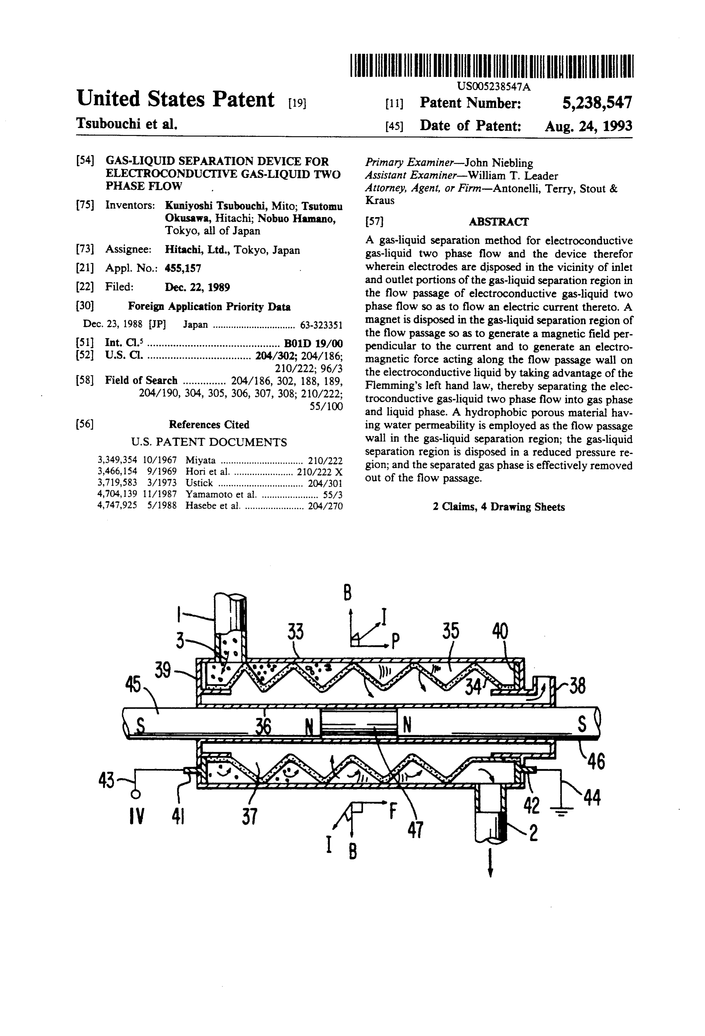
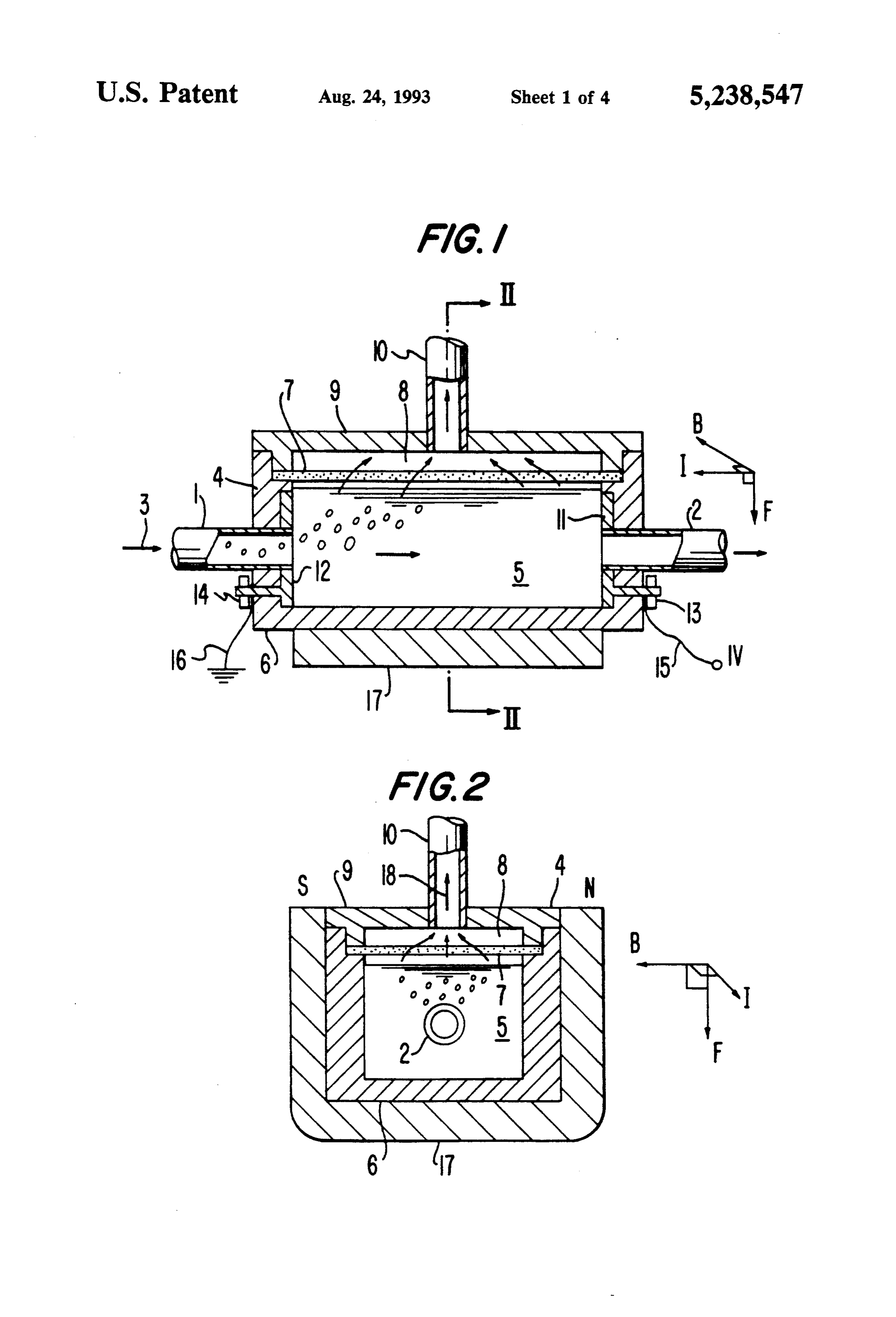
However, such as in devices relating to bioscience deal 50 BRIEF DESCRIPTION OF THE DRAWINGS ing with expensive physiological active material where a sample of trace quantity of flow rate is handled, gener FIG. 1 is a cross sectional view of a gas-liquid separa ation of the swirl components by the flow of sample tion device for electroconductive gas-liquid two phase itself is difficult. On the other hand, in the method of flows according to the first embodiment of the present disposing the vane wheel in the flow passage and 55 invention;
forcedly generating the swirling components, there FIG. 2 is a cross sectional view along line II-II in exist many problems such as sealing, lubrication and FIG. 2;
biological contamination. FIG. 3 is an explanatory view illustrating acting di Examples of separation devices for gas-liquid two rection of electromagnetic force;
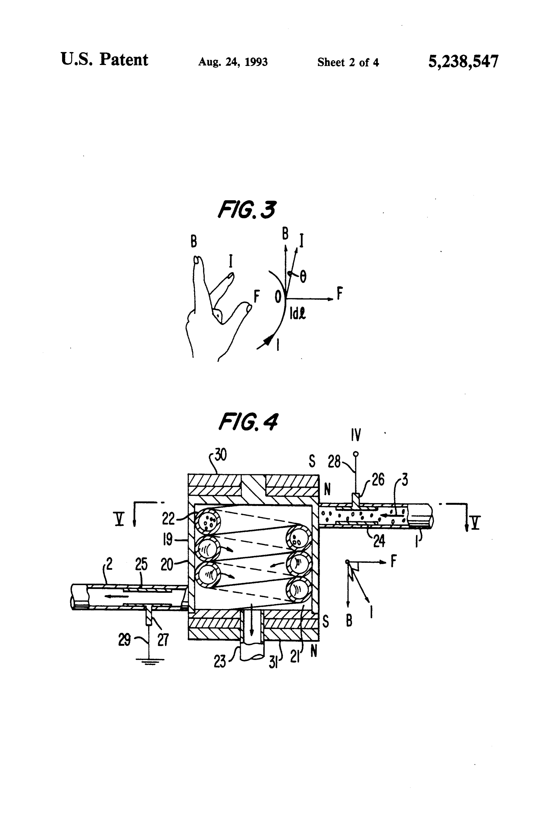
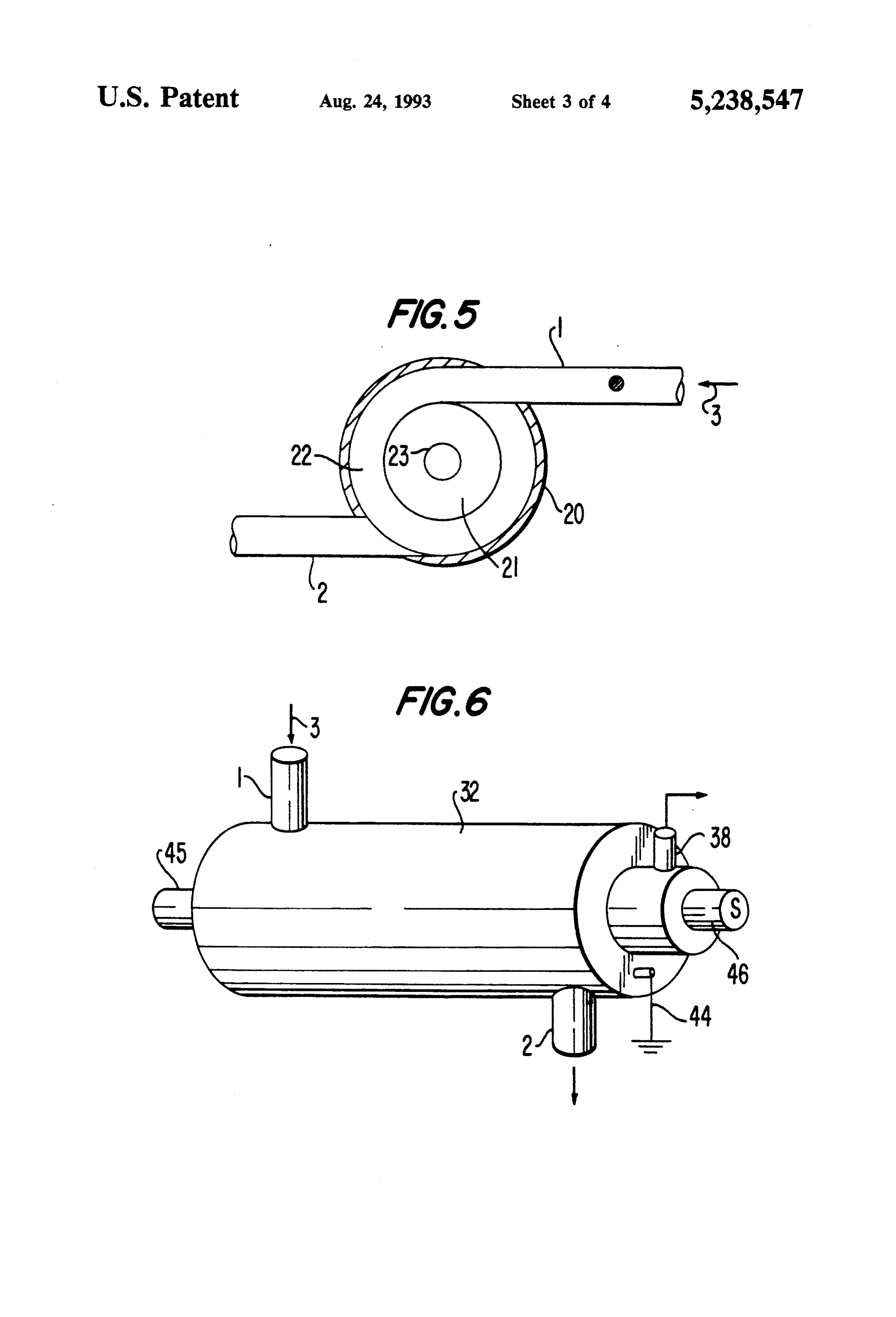
phase flows effective under such microgravity environ FIG. 4 is a cross sectional view of the second embodi ment were proposed in Japanese Patent Application ment according to the present invention; Laid-Open Nos. 58-88012 (1983) and 58-88013 (1983) FIG. 5 is cross sectional view along line V-V in wherein electrodes in ring shape and the like are dis FIG. 4;
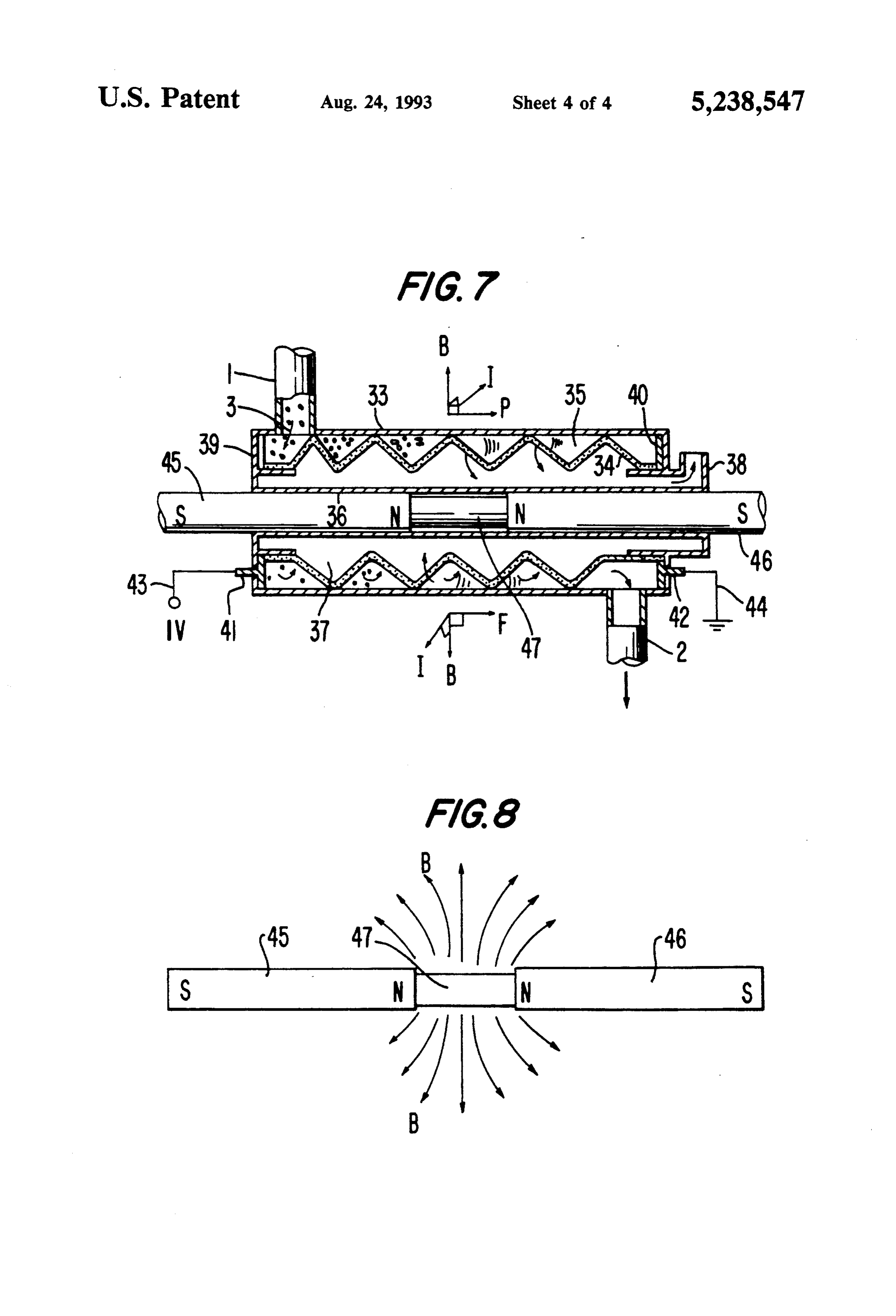
posed along the flow passage of electrical insulation FIG. 6 is a perspective view of the third embodiment gas-liquid two phase flow, a high electric field region 65 according to the present invention; and a low electric field region are formed and the gas FIG. 7 is a cross sectional view of FIG. 6; and phase in the electrical insulation gas-liquid two phase FIG. 8 is an explanatory view illustrating magnetic flow is collected. field vectors.
Page 7
DETAILED DESCRIPTION OF THE netic field acts on the current to cross perpendicularly. PREFERRED EMBODIMENTS When there is a current flowing conductor in the magnegic field, an electromagnetic field acts on the
Hereinafter the gas-liquid separation device for elec conductor. The direction thereof, as shown in FIG. 3, is troconductive gas-liquid two phase flow according to determined by Flemming's left hand law. That is, when one embodiment of the present invention will be ex the current I and the magnetic field Bact in the direc plained with referrence to FIG. 1 and FIG. 2. tions shown in FIG. 3, the electromagnetic force Facts As shown in FIG. 1, the present embodiment shows in the direction also shown in FIG. 3. The force is ex an example wherein a gas-liquid separation device 4 is pressed as follows;
provided in a part of the flow passage of gas-liquid two O phase flow. A separation chamber 6 is provided which dF=BI sin) dil contains an electroconductive gas-liquid two phase flow 3 therein and constitues gas-liquid separation re Where gion 5. To this separation chamber 6 a gas-liquid two 8: Angle between the current I and magnetic field phase tube 1 for charging the gas-liquid two phase flow 15 dl: Extremely short length of the conductor and a liquid phase discharging tube 2 for discharging Therefore, with the embodiment of FIG. 1 and FIG. the liquid phase after separation are connected. Above 2, in the separation chamber 6, the current I flows from this separation chamber 6 a hydrophobic membrane 7 of the downstream side to the upstream side along the axial fluorocarbon system having gas permeability is dis flow direction of the electroconductive gas-liquid two posed, and a reduced pressure chamber 8 is formed 20 phase flows, the magnetic field is formed in a direction outside the hydrophobic membrane 7 with a cover perpendicular to the sheet of FIG. 1 from up to down, member 9. A gas phase discharge tube 10 is provided at in other words, from N pole to Spole as shown in FIG. a part of this cover member 9, and the above mentioned 2; therefore, to the electroconductive liquid as a con reduced pressure chamber 8 is connected to a pressure ductor is applied an electromagnetic force F directing reducing device (not shown), such as a vacuum pump. 25 to the inner wall face of the separation chamber oppos In such gas-liquid separation device 4 of the present ing to the hydrophobic membrane having gas permea embodiment, a high voltage side electrode 11 and a low bility as shown in the drawings. That is, among the voltage side electrode 12 are respectively provided on gas-liquid two phase flow including many bubbles, only the opposing inner wall faces of the separation chamber the liquid having electroconductivity, with the action of 6 as well as connected to outer power supply 15 and to 30 the electromagnetic force F, gradually drifts to the the ground 16 through electrode terminals 13 and 14. direction opposite to the hydrophobic membrane 7, Although, in the present embodiment, the high voltage therefore as a matter of course, the bubbles therein drift side electrode 11 is disposed on the inner wall of the toward the hydrophobic membrane 7 and the gas phase separation chamber 6 where the liquid phase discharge and the liquid phase are separated. As will be under tube 2 is connected, and the ground side electrode 12 is 35 stood, the gas phase is separatedly collected in the vicin on the inner wall of the separation chamber 6 where the ity of the hydrophobic membrane 7 having gas permea gas-liquid two phase tube 1 is connected, the present bility, when the internal pressure of the reduced pres invention is not limited to this disposition and such is sure chamber adjacent to the opposite side of the hydro determined in consideration of e.g., the flow direction phobic membrane 7 is decreased; that is, the gas phase of the gas-liquid two phase flow and acting direction of 40 passes through the microscopic holes of the hydropho the electromagnetic force. bic membrane 7 into the reduced pressure chamber 8 On one hand, adjacent to the outer wall face of the and is removed out of the system through the gas phase separation chamber 6 in the gas-liquid separation device discharge tube 10. On one hand, the electroconductive 4, a magnet 17 is disposed so that magnetic field acts liquid remaining in the separation chamber 6 is rendered toward the direction perpendicular to the line connect 45 to a liquid phase without bubbles and flows down to the ing the above pair of opposing electrodes 11 and 12. liquid discharge tube 2.
As the constitutional example shown in FIG. 2 which FIG. 4 and FIG. 5 show a gas-liquid separation de is a cross section along the line II-II in FIG. 1, in the vice for electroconductive gas-liquid two phase flows present embodiment, the magnetic field generated with according to the second embodiment of the present the N and Spoles of the magnet 17 crosses perpendicu 50 invention. In the embodiment shown, the gas-liquid larly to with the pair of electrodes 11 and 12. In addi separation device 19 is provided with a separation tion, the N and Spoles are disposed so as to cross per chamber 20 of a cylindrical shape of which both ends pendicularly to the flow direction of gas phase 18 in the are tightly closed, and, in the inner space 21 thereof, a gas-liquid separation device 4 from the gas-liquid sepa coiled gas-liquid separation tube 22 formed of a hydro ration region 5 to the reduced pressure chamber 8 55 phobic membrane material having gas permeability is through the hydrophobic membrane 7 having gas per disposed, and is connected to the gas-liquid two phase meability. tube 1 introducing the gas-liquid two phase flow 3 and In the gas-liquid separation device 4 thus constituted, to the liquid phase discharge tube 2. On one hand, a gas when the electroconductive gas-liquid two phase flow 3 phase discharge tube 23 is provided at one end face of is introduced into the gas-liquid separation region 5 in the separation chamber 20 and is communicated with the separation chamber 6 through the gas-liquid two the inner space 21 which is constituted to be in a re phase tube 1 and the external power supply voltage 15 duced pressure In such gas-liquid separation device 19 is applied to the pair of electrodes disposed on the inner too, a pair of electrodes 24 and 25 are provided at the wall of the separation chamber 6 through the terminals inside of the gas-liquid two phase the 1 for the flow-in 13 and 14, current flows through the liquid in the gas 65 side and at the inside of the liquid phase discharge tube liquid separation region 5. On one hand, N and Spoles 2 for the flowout side, as well as are connected to a high of the magnet 17 are arranged to cross in perpendicu voltage side power supply 28 and the ground 29 larly to the direction of the current, thereby the mag through respective terminals 26 and 27. Further, mag
Page 8
nets 30 and 31 are provided on the both end faces of the which is different from those of the previous embodi cylindrical separation chamber 20 and N and Spoles are ments, rod shaped magnets 45 and 46 are inserted into disposes so as to oppose each other and to create a the axial center portion of the gas-liquid separation magnetic field. device 32 and arranged to face the respective N poles of With the gas-liquid separation device 19 of the pres the magnets through a cylinder 47 of soft steel. By the ent embodiment, the electroconductive gas-liquid two employment of such magnet arrangement, the magnetic phase flow 3 flows into the gas-liquid separation tube 22 field B causes the magnetic flux to act in a radial direc from the gas-liquid two phase tube 1, flows down inside tion from the axial center portion as shown in FIG. 8, the coiled gas-liquid separation tube 22 in the separation and the radial magnetic fieled vector acts on the separa chamber 20 and is effected more or less by an action of 10 tion flow passage 35 of the present embodiment in the centrifugal force. Further, with the pair of electrodes radial direction from the axial center portion. As a re disposed at the inlet and outlet portions of the flow sult, when current I flows in the electroconductive passage current I flows through the electroconductive gas-liquid two phase flow 3 passing through the spirally liquid and with the magnets 30 and 31 provided at the constituted gas-liquid separation flow passage 35, as both ends of the separation chamber in opposing rela 15 shown in FIG.7 the electromagnetic force Facts on the tion magnetic field B is formed in the axial direction of liquid phase in the axial direction and the gas phase and the cylindrical separation chamber 20. Therefore, the the liquid phase are gradually separated. In the above electroconductive liquid in the coiled gas-liquid separa mentioned second embodiment, when the gas-liquid tion tube 22 is forced toward the outer circumferential separation tube passage is elongated, the distance be side by the effect of the electromagnetic force F, 20 tween the magnets becomes large and the magnetic thereby, the included bubbles are concentrated toward field vector tends to be rendered weak; however, with the inner circumferential side. Thus the gas-liquid two the present embodiment, the strength of magnetic field phase flow is gradually separated into gas phase and vector does not substantially change even if the separa liquid phase. Further, in the present embodiment, since tion flow passage is enlarged, and therefore, it is ex the gas-liquid separation tube 22 is formed of a hydro 25 pected to maximize gas-liquid separation capability by phobic membrane having gas permeability, when the the electromagnetic force. Althouth, in the present internal space 21 of the separation chamber 20 is ren embodiment, the spiral separation flow passage 35 is dered under a reduced pressure condition, only the gas constituted with the hydrophobic membrane 34, a sepa phase collected in the inner circumferential side of the ration tube of hydrophobic membrane may of course be gas-liquid separation tube 22 passes through the tube 30 constituted in a coil shape like the previous embodi wall into the internal space 21 and is separated and ments.
removed out of the system through the communicating Further, although in the above embodiments, mag gas phase discharge tube 23. Particularly with the pres nets (permanent or electromagnets) are employed as an ent embodiment, by the constitution of the coiled gas magnetic field generating device, when a superconduc liquid separation tube 22 in addition to the electromag 35 tive magnet is employed, the magnetic field vector can netic force F, a centrifugal force acts on the internal be increased and the electromagnetic force also in liquid, due to their multiplier effect, a separation effi creased such that the gas-liquid separation is possibly ciency equal to or more than that of the first embodi carried out in a short time.
ment is obtained with the present embodiment. According to the respective embodiments of the pres FIG. 6 and FIG. 7 show a gas-liquid separation de ent invention, even in cases when an electroconductive vice for electroconductive two phase flows according sample including mixed gas and liquid, such as expen to the third embodiment of the present invention. The sive physiological active material, is treated, where gas-liquid separation device 32 of the present embodi generation of swirl components by the flow of the sam ment shown in the FIGS. 6 and 7 is elongated along the ple itself is difficult due to trace quantity of the flow rate axial direction and includes a doubled cylindrical shape 45 or microgravity environment such as in space, and, thus separation chamber 33, in the inner space of which a gas-liquid separation is difficult, by flowing current in spiral shaped gas-liquid separation flow passage 35 for the gas-liquid two phase flow and generating a mag passing the gas-liquid two phase flow is disposed and is netic field, a strong electro-magnetic force is actable on formed by using a hydrophobic membrane 34 having the liquid phase as conductor, and the separation be gas permeability. Further, in the inner circumferential tween gas phase and liquid phase can be easily achieved. side thereof, which is surrounded by the hydrophobic Further since no movable parts are included in the membrane 34 and a cylinder wall 36, a reduced pressure internal flow passage, the structure thereof is simplified chamber 37 is formed, and at one end face thereof a gas and a clean and reliable gas-liquid separation device for phase discharge tube 38 is communicatively disposed. biological materials sensitive to contamination is obtain On one hand, the gas-liquid separation flow passage 35 55 able. In addition, although data will differ depending formed at the outer circumferential side of the hydro upon the specific structure of the separation device, in phobic membrane 34 communicates with the gas-liquid the structure of the third embodiment, when a perma two phase tube 1 in the vicinity of one axial end of the nent magnet of 20K gauss and current of 0.25A/cm2 cylindrical separation chamber 33 as well as with the were employed, it was determined that a electromag liquid phase discharge tube 2 in the vicinity of the other 60 netic force corresponding to at least acceleration of axial end of the separation chamber. Further a pair of several 10 g was obtained.
electrodes 39 and 40 are provided on the respective According to the gas-liquid separation method for inner wall sides of both axial ends of the separation electroconductive gas-liquid two phase flows and the chamber 33 in the portion where the gas-liquid separa device therefor of the present invention explained tion flow passage contacts as well as are connected to, 65 above, the electrodes are disposed in the vicinity of the respectively, an external high voltage side power sup inlet and outlet portions of the gas-liquid separation ply 43 and the ground 44 through terminals 41 and 42. region in the flow passage of electroconductive gas-liq On one hand, as a method for generating magnetic field, uid two phase flow so as to flow electric current there
Page 9
between; the magnet is disposed in the gas-liquid separa posed on the inner wall side of an axial end member of tion region of the flow passage so that the magnetic said separation chamber and in the portion contacting field act perpendicularly to the current; an electromag to said gas-liquid separation flow passage; at least two netic force along the flow passage wall acts on the magnets disposed along the central axis of the inner electroconductive liquid by taking advantage of Flem cylinder so that the same polarities thereof face each ming's left hand law; and the gas phase and the liquid other and generate a radial magnetic field in the radial phase are separated from the electroconductive gas-liq direction from the central axis.
uid two phase flow, so that even in a microgravity 2. A gas-liquid separation device for electroconduc environment and in a trace quantity flow rate condi tive gas-liquid two phase flow comprising inner and tion, a gas-liquid separation method for electroconduc O outer cylinders defining a separation chamber in an tive gas-liquid two phase flow and the device therefor annular region between the cylinders, both ends of the capable of a stable gas-liquid separation is obtained. separation chamber being tightly closed by a pair of We claim: axial end members; a coiled gas-liquid separation tube in 1. A gas-liquid separation device for electroconduc the annular region formed by using a hydrophobic tive gas-liquid two phase flow, comprising inner and 15 membrane material having gas permeability for passing outer cylinders, one arranged within the other defining the electroconductive gas-liquid two phase flow; a re a separation chamber in an annular region between the duced pressure chamber in the annular region formed cylinders, both ends of the separation chamber being on an inner circumferential side of said coiled gas-liquid tightly closed by a pair of axial end members; a spiral separation tube and surrounded with said hydrophobic shaped gas-liquid separation flow passage in said annu 20 membrane material, the inner cylindrical wall of said lar region formed by using a hydrophobic membrane separation chamber and the pair of axial end members; having gas permeability for passing the electroconduc a gas discharge tube connected to one axial end member tive gas-liquid two phase flow; a reduced pressure of said pressure reduced chamber for discharging the chamber in said annular region formed on an inner gas phase separated; a gas-liquid two phase tube con circumferential side of said gas-liquid separation flow 25 nected to the separation tube near one end of said sepa passage and surrounded with said hydrophobic mem ration chamber for introducing the electroconductive brane, the inner cylindrical wall of said separation gas-liquid two phase flow into said cooled gas-liquid chamber and the pair of axial end members; a gas dis separation tube; a liquid phase discharge tube connected charge tube connected to one axial end member of said to the separation tube near the other end side of said pressure reduced chamber for discharging the gas phase 30 separation chamber for discharging the liquid phase separated; a gas-liquid two phase tube connected to the after the gas is separated in said coiled gas-liquid separa flow passage near one end of said separation chamber tion tube; a pair of electrodes, each of said pair of elec for introducing the electroconductive gas-liquid two trodes being disposed at an end of said separation cham phase flow into said gas-liquid separation flow passage; ber and being adapted to contact with the gas-liquid a liquid phase discharge tube connected to the flow 35 two phase flow; at least two magnets disposed along the passage near the other end of said separation chamber central axis of the inner cylinder so that the same polari for discharging the liquid phase after the gas is sepa ties thereof face each other and generate a radial mag rated in said gas-liquid separation flow passage; a pair of netic field in the radial direction from the central axis. electrodes, each of said pair of electrodes being dis k k k k
Provenance
- Collection
- Cited prior art
- Original PDF
- patentimages.storage.googleapis.com →
- Filed
- 1989-12-22
- Pages
- 9
- Method
- pdftotext (the PDF's own text layer) + pdftoppm 300dpi page scans
- Source
- Google Patents bibliographic record
- Granted
- 1993-08-24
- Inventors
- Kuniyoshi Tsubouchi; Tsutomu Okusawa; Nobuo Hamano; Hitachi Ltd
- Transcribed from
- patentimages.storage.googleapis.com →