patent · US4606322
Dual fuel control and supply system for internal combustion engines
19 August 1986
Page 1 — bibliographic record
United States Patent (19) 11 Patent Number: 4,606,322 Reid et al. (45) Date of Patent: Aug. 19, 1986 54) DUAL FUEL CONTROL AND SUPPLY FOREIGN PATENT DOCUMENTS
SYSTEM FOR INTERNAL COMBUSTION
ENGINES 0102119 8/1983 European Pat. Off............. 123/375
75) Inventors: Harvey M. Reid, 11 Wakefield 2112457A 12/1982 United Kingdom ................ 123/375 Street; Neil R. Poletti, both of Lower
Hutt; Jonathon B. Rainey, Primary Examiner-Carl Stuart Miller
Wellington; George L. Jones, Attorney, Agent, or Firm-Poms, Smith, Lande & Rose Wainuiomata, all of New Zealand 57 ABSTRACT 73) Assignee: Harvey Marshall Reid, New Zealand An electrically controllable dual fuel system for an
internal combustion engine (such as, but not necessarily confined to, a diesel engine) having a liquid fuel injec 22 Filed: Jul. 25, 1984 tion system incorporating an injector pump for deliver ing prescribed quantities of a principal liquid fuel (e.g.
(30) Foreign Application Priority Data diesel oil) under pressure to individual injectors for the Aug. 4, 1983 NZ New Zealand ........................ 205140 engine cylinders comprising an electronic control unit, an electrically controllable variable flow regulator ar 51 int. Cl." ............................................. F02M 39/00 ranged to receive a combustible alternative fuel (e.g. a 52 U.S. Cl. .................................... 123/575; 123/458; gas such as CNG or LPG) under pressure and deliver 123/494; 123/514; 251/129.09 controlled quantities of the alternative fuel to the engine 58) Field of Search ................ 123/575, 576, 577-578, as determined by signals received by and transmitted 123/458, 494, 459, 460, 514; 251/137, 140 from said electronic control unit, by-pass bleed means
for bleeding fuel from the principal fuel injection system at the output side of the injector pump and before the
1,395,203 10/1921 Olsen ................................... 251/140 trol system which includes pressure or flow actuated 3,190,608 6/1965 Hassa .... ... 251/127 means for measuring the quantity of fuel bled from the 3,949,713 4/1976 Rivere .......... ... 123/458 injection system and supplying a corresponding signal 4,260,333 4/1981 Schillinoer ... ... 123/458 to the control unit.
4,361,309 11/1982 Sogabe......... ... 251/137 4,495,930 1/1985 Narajima ............................. 123/575 18 Claims, 7 Drawing Figures
Page 2
Drawing sheet — no readable text.
Page 3
Drawing sheet — no readable text.
Page 4
Drawing sheet — no readable text.
Page 5
Drawing sheet — no readable text.
Page 6
over a period of time by way of orifices opened and
DUAL FUEL CONTROLAND SUPPLY SYSTEM closed by the injection plungers whereas in the jerk FOR INTERNAL COMBUSTON ENGINES pump systems the fuel pressure is raised considerably (e.g. to about 20 MPa) by the injector plungers or
This invention relates to internal combustion engines, 5 pumping elements for substantially instantaneous deliv and more particularly relates to compression ignition or ery injection into the combustion chambers of the en diesel engines designed for operation by high pressure gine. In the Cummins PT or common rail systems, fuel injection of a liquid 'diesel fuel oil and the adaption of supplied to the injector pump in excess of the engines such engines to run on a combination of liquid "diesel requirements is usually continually by-passed back to fuel and an alternative fuel, as for example a gaseous O the supply source from the pump. fuel such as a compressed natural gas (CNG), biogas or The fuel control system according to U.K. Applica producer gas, methane, liquid petroleum gas (LPG) or tion No. 8235252 is able to employ and control a gas any other suitable gaseous or alternative liquid fuel metering valve for alternative fuel supply according to combustible in a compression ignition engine. The in variations in rail pressure in the injector pump deter vention may also have application in whole or in part to 15 mined by draw-off or quantities delivered to the engine, engines designed to operate on petrol and like fuels, and it is apparent that this system is always dependent requiring spark ignition and employing a fuel injection on the flow pressure of the liquid fuel to indicate and system. control the amount of alternative fuel (gas) to be deliv Early attempts at using alternative fuels in diesel ered to the engine. The fuel control system according to engines relied primarily on finding a fuel with similar 20 EP Application No. 0 108 582 employs and controls a ignition temperatures to that of conventionally used gas supply regulator according to pressure variation in liquid diesel fuel, or to use blends of alternative liquid the common rail mimicked by a flow restrictor as deter fuels and conventional liquid diesel fuel. It was then mined by way of a fuel oil reference supply line con found that alternative gaseous fuels with low ignition nected as part of the circulatory system downstream of the temperatures and high volatility could be mixed with 25 throttle control, and sensor means responsive to pres the air entering the engine and ignited at the appropriate sure in such reference supply line. Both systems are moment by the conventional liquid diesel fuel injection. designed primarily for common rail or circulatory sys Control of the amount of the two fuels required for tems and rely on the maintenance of normal pressure at operation was relatively easy with constant load sta the injector pump to indicate the actual amount of gas tionary engines, and there is a considerable amount of 30 or alternative fuel to be delivered to the engine. prior art in this field. However, the control of fuel sup In the case of EP application No. 0 102 119, the dis ply is not easy with such as transport vehicles agricul closed system is indicated as being applicable to engines tural machines and heavy motorised equipment subject with fuel injector pump systems of various kinds and to widely varying load/speed conditions on the engines. not just the Cummins types, but the system does employ Various attempts to control the fuel proportions have 35 a diesel fuel return line from the injector pump and the mainly been aimed at fractionally reducing the liquid control of gas as the alternative fuel is necessarily deter diesel fuel injected, but the control algorithm is not mined by a signal produced as a result of comparison of linear because of the severe non-linearity of typical fuel the liquid fuel flow through the main feed line and the injection pump characteristics and the lack of precise return line. However, the system is also particularly control over the supply of the alternative fuel. Accord directed to an arrangement in which gas fuel supply is ingly, in the main moderate replacement of the liquid limited according to governor control lever operation diesel fuel by the alternative fuel has had to be accepted (which would involve load sensitivity only) and is fur so that the engine runs reliably and does not produce ther concerned with substitution of relatively low per more than its designed torque output. It has also been centages of gas as the alternative fuel. found that necessary liquid fuel control often involves 45 An object of the present invention is to provide an altering the characteristics of the injection pump, caus electronically controllable dual fuel system particularly ing difficulty in fitting the required components. for (but not necessarily confined to) typical liquid fu More recent developments aimed at improving the elled diesel or compression iginition internal combus control of dual fuel supply to diesel engines have been tion engines and applicable to various kinds of fuel made, and reference may be had in particularly to the 50 injector systems; such system being effective and effi specifications of United Kingdom Patent Application cient in operation and over a wide range of operating No. 8235252 (publication No. 2112457A), and European conditions and providing for substantially instantaneous Patent Applications Nos. 0108582 and 0 102 119. How variable control of both alternative fuel and liquid diesel ever, the dual fuel systems according to the first two of fuel supply (the principal liquid fuel) to the engine and these specifications are more particularly directed to 55 preventing the admission of excess alternative fuel and the conversion and operation of diesel engines having /or the injection of excess liquid diesel fuel when the circulatory or "common rail' fuel oil injection supply engine is under any condition.
systems, and in particular the "Cummins' diesel engines Another object of the present invention is to provide having pressure/time (“PT") fuel injection systems, and a control mechanism for a diesel/alternative fuel dual the systems disclosed cannot be efficiently and effec fuelled engine that is accurate, does not allow over or tively applied to engines having other liquid diesel fuel under energising of the engine, is easy to install and injection systems such as the more common jerk pump' maintain and can be easily matched to the characteris fuel injection systems. It is important to note that in the tics of any diesel engine.
common rail or Cummins PT fuel injection systems The present invention further provides a dual fuel liquid fuel is delivered from the injection pump to the 65 control system and equipment which is particularly injector inelts metering orifices at a substantially con applicable to engines having a liquid fuel injection sys stant relatively low final delivery pressure (e.g. about tem for the principal liquid fuel, and whereby the sup 700 kPa) for dispensing prescribed quantities of fuel ply of an alternative or supplementary fuel can be di
Page 7
rectly and accurately controlled in proportion to nor The invention further includes the provision of com mal liquid fuel usage so as to match the engine torque ponents as a kit set for the fitting of the system to exist CVe. ing engines, and new or existing engines incorporating Other and more particular objects, advantages and the system and components, and vehicles having such applications of the present invention will become appar engines and systems.
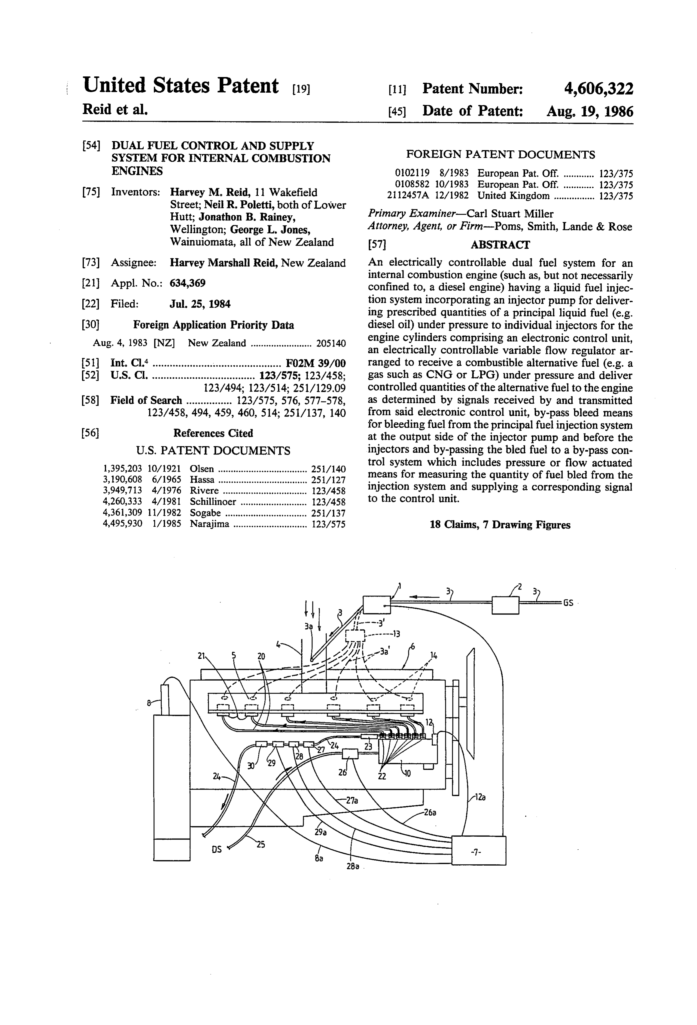
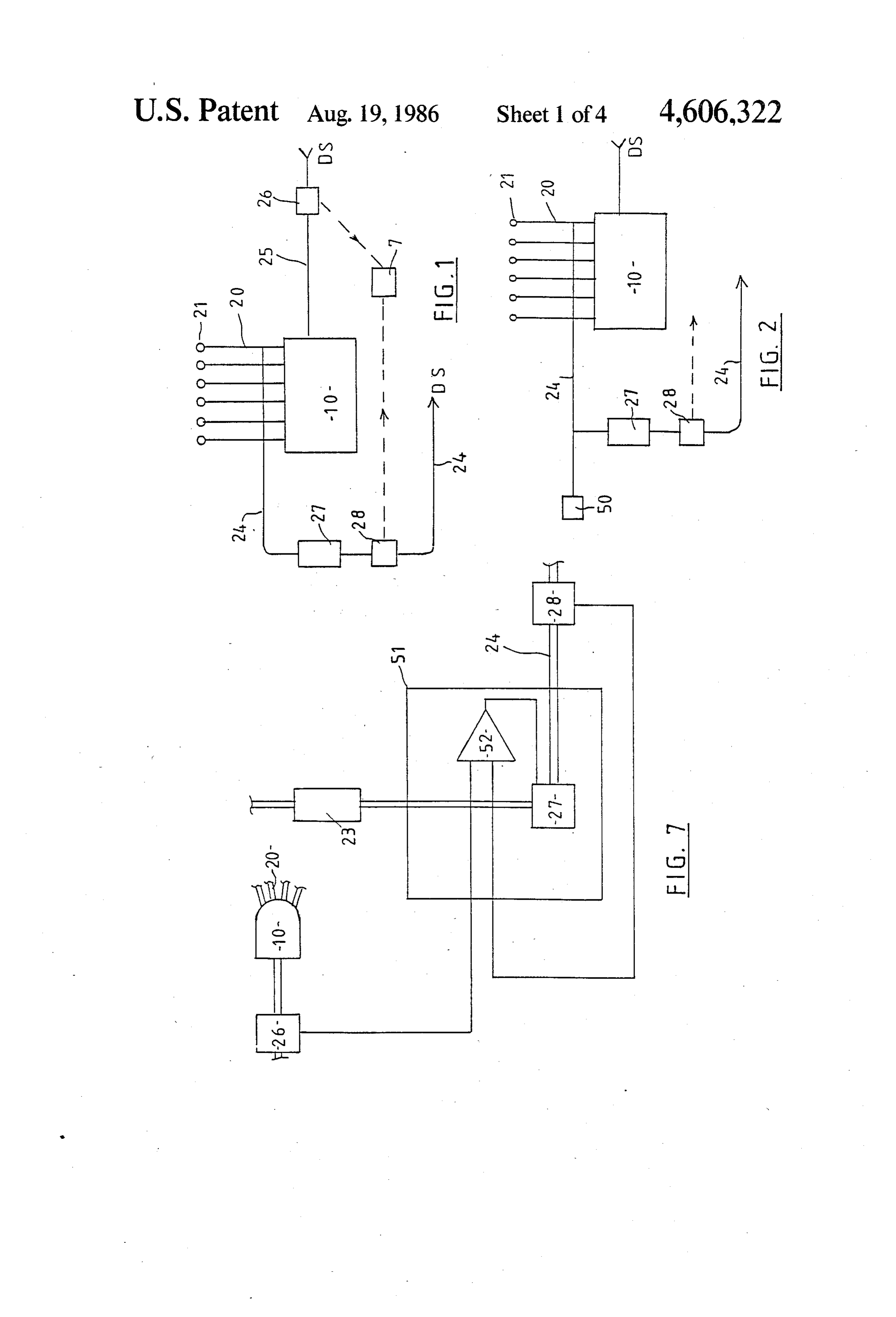
ent from the ensuing description. Some preferred aspects of the invention will now be If the liquid diesel fuel injection is treated as primarily described by way of example and with reference to its an ignition source, then the alternative fuel, introduced application to diesel engines in particular and the en as a gas or vaporised fuel into the engine with the air, ployment of a gaseous fuel as the alternative fuel, and provides most of the energy to drive the load. Simplisti 10 with reference to the accompanying drawings in which: cally, the amount of liquid diesel fuel injected can be a FIG. 1 is a schematic diagram illustrating the basis of constant, just enough to light the alternative fuel, and one form of the principal system in accordance with the independant of the speed or load on the engine. Also present invention.
simplistically, the amount of alternative fuel introduced 15 FIG. 2 is a schematic diagram illustrating the basis of needs to equal the difference between the actual fuel an alternative form of the system.
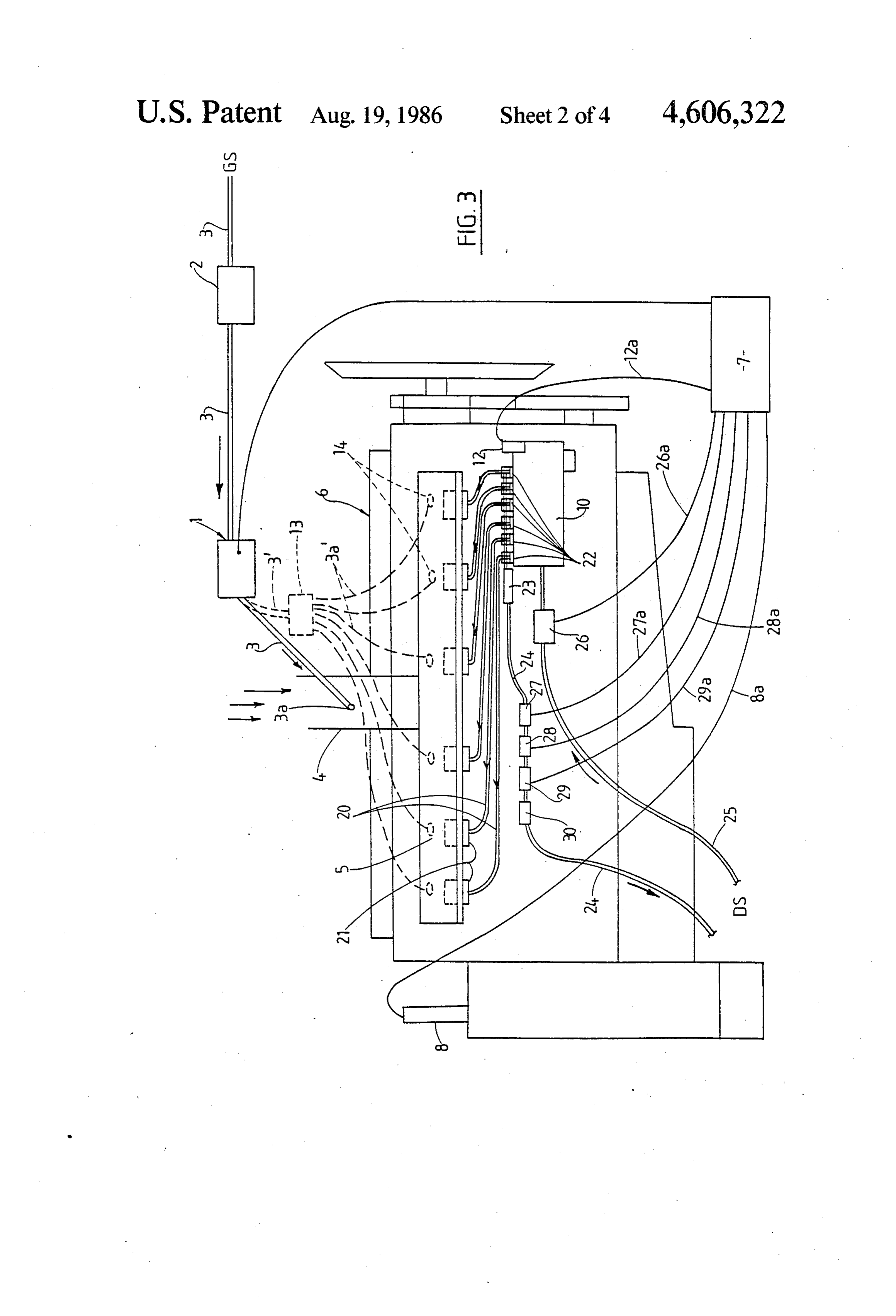
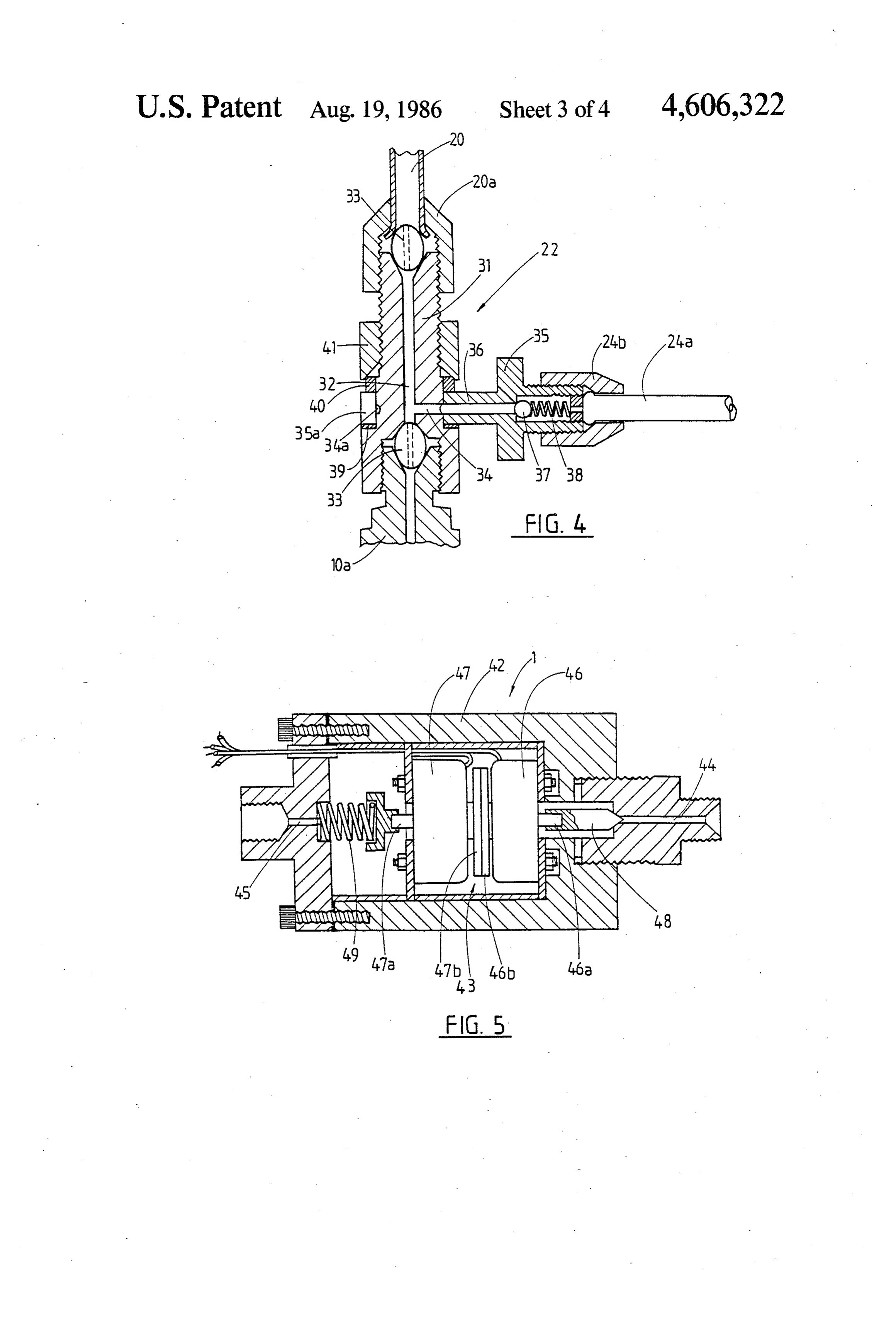
used and what would have been used under the same FIG. 3 is a diagrammatic side elevational view illus engine conditions using full diesel fuelling. If, as is con trating the general arrangement of an engine incorpo templated by the present invention, a by-pass is pro rating the system in accordance with the invention. vided between the injector pump and the injectors, to FIG. 4 is a sectional view more particularly illustrat bleed off a controlled amount of diesel and return it to ing one means for effecting bleeding off of liquid fuel the liquid diesel fuel supply tank, then this will provide from an injector pump system having exposed injector a means of varying the amount of diesel injected into feed pipe, the engine; and if a controlled pressure regulator dis FIG. 5 is a longitudinal sectional view illustrating one penses the alternative fuel into the air intake of the 25 preferred form of variable flow regulator usable in the engine, then this will provide a means of controlling the system according to this invention. amount of this fuel provided to the engine. By further FIG. 6 is a schematic diagram more particularly elab providing a means to measure the amount of liquid orating upon the basis of the system according to FIG. diesel fuel bypassed and relate this to the known or 2, and calculated requirements of the engine, then this will 30 FIG. 7 is a schematic diagram illustrating part of the provide information to control the amounts of the two system according to FIG. 1.
fuels required by the engine. Referring firstly to FIGS. 1 and 2 of the drawings the According to one aspect of the present invention basis of the principal liquid fuel (diesel fuel) and alterna therefor, there is provided an electronically controlla tive fuel (gas) control and supply system of this inven ble dual fuel system for an internal combustion engine 35 tion is the employment of a liquid fuel by-pass system having a liquid fuel injection system incorporating an whereby a by-pass line 24 is provided to be capable of injector pump for delivering prescribed quantities of a by-passing quantities of liquid diesel fuel from the out principal liquid fuel under pressure to individual injec put side of the normally provided injector pump assem tors for the cylinders of the engine; comprising an elec bly 10 such as by way of appropriate by-pass fittings (as tronic control unit, an electrically controllable first described later with reference to FIGS. 3 and 4, in variable flow regulator arranged to receive a combusti particular), connected to the delivery lines 20 between ble alternative fuel under pressure and deliver con the injector pump 10 and engine cylinder injectors 21, trolled quantities of said alternative fuel to the engine as and means for measuring the precise quantity of liquid determined by electrical signals received by and trans fuel by-passed against that normally supplied or calcu mitted from said electronic control unit, by-pass bleed 45 lated as being required to be supplied to meet the engine means for bleeding liquid fuel from the principal liquid loading and speed under certain conditions and trans fuel injection system at the output side of the injector mitting a signal to an electronic control unit 7 (such as pump and before the injectors and by-passing the bleed a microprocessor) which can electronically control the fuel to a by-pass control system, said by-pass control precise amount of alternative fuel or gas required to be system including means arranged to measure the quan 50 delivered to the engine at that time to perform the tity of fuel bled from the output side of the injection amount of work equivalent to the work that would have system and supply a corresponding electrical signal to been performed by the by-passed liquid fuel under the said electronic control unit, said electronic control unit same conditions. Because of the complexity of the rela determining the energy value of the proportion of prin tionship between the by-passed flow and engine speed cipal liquid fuel normally intended to be supplied to the 55 on the one hand, and the set points of the two fuel con engine to meet the engines demands at that time but trollers on the other, it is necessary to provide a versa bled from the injection system and controlling the pre tile control mechanism like a microprocessor to handle scribed amount of electric power to said variable flow these complexities. This makes it relatively easy to im regulator to enable delivery to the engine of the pre prove the control algorithm by adding other transduc scribed quantities of alternative fuel proportional in ers as inputs, or mathematically manipulating the signals energy value to that necessary to maintain the required for particular engine circumstances. Liquid diesel fuel is . power rating and/or speed of the engine for normal supplied to the injector pump 10 from the normally efficient operation. provided tank or supply source DS and the by-passed Other aspects of the present invention include the liquid fuel is returned to the source DS in a closed loop system according to the preceding paragraph with fur 65 system, and a variable flow regulator 27 controlling the ther components and additional signal generation and amount of liquid fuel by-passed is provided in the by supply to the electronic control unit for further control pass line 24, the operation of the variable flow regulator and effective efficient operation of the engine. 27 being electronically controlled by the control unit 7.
Page 8
The system according to FIG. 1 can rely upon a flow bore gas fuel pipes 3 when compared with many known comparison system utilising a first input flowmeter 26 in systems requiring large diameter gas feed pipes because the diesel fuel feed line from the supply source DS to of the supply of gas under relatively higher pressure the injector pump 10 and a by-pass flowmeter 28 in the than usual e.g. many known systems employ gas supply by-pass line 24 between the variable flow regulator 27 for feed pipes in the range or excess of 25 millimeter and return to the supply source DS, both flowmeters 26 bore whereas the present invention may utilise small and 28 transmitting signals to the control unit 7 for flow bore pipes of say six to eight millimeters internal diame comparison with the signal from the by-pass flowmeter terbore for a medium size diesel engine. 28 determining the liquid fuel fluctuation or quantity In the case of engines having a pressurised or boosted by-passed and thus the basis for calculation by the con O air intake system e.g. as in turbo-charged or super trol unit 7 of the equivalent energy gas required to be charged engines, difficulties may arise in feeding gas to supplied. Whilst the flowmeter comparison system can the air intake as mentioned above. Accordingly (and be advantageously employed in many instances and has indicated in broken outline in FIG.3 of the accompany the particular advantage of being capable of adjusting ing drawings) the system can employ an arrangement the iquid diesel fuel/gas ratio through all load and speed 15 with the gas fed by way of conduit 3' to a gas distributor ranges, there can be some disadvantages in a low pres 13 and conduits 3a' to individual electronically con sure liquid fuel supply system with the requirement for trolled valves 14 for each cylinder of the engine. The pipework than is convenient to use may be necessary distributor unit 13 thus divides the gas supply equally and added junctions and components increase possible between the pipes or ducts 3a' to the respective cylin risk of dirt and/or air entry to the system. 20 ders, and such pipes or ducts 3a are all preferably of It has been discovered that a varying pressure occurs equal bore diameter and equal length to ensure that in the by-pass line 24 and which pressure varies accord there is an equal volume of gas at equal pressure avail ing to the engine load and speed; and by maintaining the able for each cylinder on demand. The feed pipes or pressure in the by-pass line between the injector lines 20 ducts 3a' are directed to the respective cylinders by way and diesel fuel flow regulator 27 a prescribed propor 25 of the inlet manifold unit 5.
tion of diesel fuel injected can be maintained. Accord The gas control valves 14 for the respective cylinders ingly, and as indicated in FIG. 2 (and to be more partic are all provided in similar locations and are preferably ularly described later with reference to FIG. 4) a pres located for each cylinder at an equal distance from the sure transducer 50 is provided in the by-pass line 24 to inlet valve in a four-stroke engine, or at an equal dis record the pressure in the by-pass line 24 and transmit 30 tance from the inlet port in the case of a two-stroke signal for control of the diesel fuel flow regulator 27 for engine, to ensure that the timing of each gas inlet valve maintenance of the prescribed pressure in the by-pass 14 can be set so that the injected gas goes into the air line 24. The flowmeter 28 is retained for providing the stream part way through the intake stroke of the piston required flow signal resulting in control of gas flow to of each cylinder so that none of the gas is lost into the the engine. The diesel/gas ratio in this alternative sys 35 exhaust system before the exhaust valve closes or ex tem is mainly variable according to engine speed and haust port is closed in each cylinder. Other timed gas not load, and may therefor not always be fully efficient admission means can be employed.
at low loads, but the system is less complicated than the The operational timing of the gas injector or admis flowmeter system and whilst component costs may be sion valves 14 for the respective cylinders is further slightly higher installation and maintenance costs may regulated by a signal from the control unit 7 based on be less than in the flowmeter system and thus this pres the information received thereby from such as an engine sure control system may be preferable in many in speed sensing transducer 8 such as a magnetic pick-up stances. It is believed however that both systems are far transducer, a fuel pressure indicator, a fuel pipe strain more efficient and effective and applicable to a wider gauge or injection pulse signal pick-up means such as a range of engines and injector pump systems than the 45 microphone, or other transducer. Each gas injector or prior arrangements known. admission valve 14 is electrically connected by wires to Referring now to the more detailed FIG. 3 of the the control unit 7 to conduct the timing signal for opera drawings and particularized forms of the invention, gas, tion of the respective valves 14; and the arrangement such as a compressed natural gas or any of the other can provide that each valve 14 can be opened for a fixed gaseous fuels referred to, is arranged to be supplied 50 period of time with a variable pressure to give the re under pressure from a gas supply source GS to a vari quired variable volume, or opened for a variable period able gas regulator 1. In high pressure and liquified gas of time to alter the volume of gas injected; or the valves supply systems, the variable regulator 1 can be pre 14 can be arranged for both operations. ceded by such as a first stage regulator 2 of any known Further, the operation of each gas injector or admis kind to bring the gas to a constant supply pressure; and 55 sion valve is preferably timed according to the predeter the variable regulator 1 is arranged to deliver by way of mined position relative to the flywheel marking or appropriate piping or conduit means 3 a prescribed equivalent "Top Dead Centre' position of the piston for quantity of the gas to the engine. In a naturally aspirated the respective cylinder, and such predetermined posi diesel engine with a non pressurised air induction sys tion can be electronically selected and/or adjusted by tem, the conduit 3 can deliver gas to the air induction way of the control unit 7 according to the information unit 4 associated with the inlet manifold 5 to the engine and/or signals fed to such unit 7. 6, the gas being admitted (as shown in full in FIG. 3) to The variable regulator 1 operation or actuation is the air induction unit 4 by any suitable gas mixer device controlled directly by electrical signals from an elec or outlet 3a whereby the gas can be delivered into the tronic control unit 7 which in turn is coupled to and air stream without restricting the air intake and there 65 arranged to receive signals from components associated fore without upsetting the volumetric efficiencies usu with the liquid diesel fuel supply as hereinafter de ally applicable to diesel engines. The present invention scribed, and also preferably from the engine speed permits the employment of relatively small diameter transducer 8 such as the magnetic pick-up transducer
Page 9
(which may be coupled to or form part of an engine ple in FIG. 4 of the drawings. This construction in speed or revolutions counter i.e. a tachometer) or other cludes a T pipe adaptor having a straight section 31 transducer or diesel fuel pulse pick-up means, the mag with one end part internally screw threaded for direct netic pick-up or other transducer providing an electric connection to the respective delivery valve holder 10a voltage pressure first signal which is transmitted by way of the injector pump 10, and the opposite end part exter of connection 8a to the control unit 7 and varies accord nally screw threaded to receive the normal fitting 2Ca ing to the speed of and load on the engine 6. for the feed pipe 20 to the respective injector valve 21. On receiving the electric signals from both the engine The straight section 31 has an axial bore 32 for the main speed transducer 8 (or other transducer) and the come flow of diesel fuel for injection and appropriate pipe ponents associated with the liquid fuel supply, and flow 10 coupling olives 33 may be utilised at the end joints. A rate as hereinafter described the control unit 7 senses by-pass bore 34 and communicating annular groove 34a diesel fuelling change, and selects the correct pressure extends from an intermediate part of the main bore 32 for gas to flow from the variable regulator 1, such regu and a transverse swivel connector piece 35, having an lator 1 adjusting the supply of pressurised gaseous fuel annular part 35a located and sealable over the medial to the correct prescribed rate for the engines needs. 5 part of the straight section 31, is provided with a com Diesel fuel is supplied to the engine 6 by a liquid fuel municating bore 36 sealable at its outer end by a ball injector pump 10 (which can be any known suitable valve 37 and biassing spring 38. The annular part 35a of kind of fuel injector pump-including jerk pumps, com the connector piece 35 may be clamped and sealed at mon rail pumps, rotary pumps or other delivery units) any convenient angle by appropriate seals 39 and 40 at and the present invention utilises the indicated by-pass either side and a locking nut 41. A by-pass pipe 24a, e.g. system associated with the output side of the injector rigid metal or reinforced and flexible, is connected to pump and whereby on change over or partial change the outer end of the connector piece 35 such as by con over from liquid diesel fuel to gas the quantity of gas nector nut 24b for communication with the by-pass supplied to the engine at any stage is maintained directly manifold 23 and line 24.
proportional to the amount of liquid diesel fuel by 25 Thus, in operation of the system, as the variable con passed from the injector pump 10 and having regard to trol regulator 27 is opened some of the liquid diesel fuel engine speed and power requirements e.g. the system normally delivered to the injectors 21 of the engine is may control the fuel proportions to 20% diesel fuel and allowed to transfer to the by-pass line 24 by way of the 80% gaseous fuel over the complete range of engine respective connectors 22 and pass through the by-pass speeds or to any other selected percentage and/or en 30 flow meter 28 and lock-off solenoid valve 29 back to the gine speed range. The percentage of substitution of gas supply tank or source DS. The quantity or flow of for diesel can be preselected throughout all engine revo by-passed fuel is measured and compared to the diesel lution speeds and throttle openings and/or according to input flow measured by input flow meter 26 and the loading factors. control unit calculates the equivalent amount of gas In applying the invention to a typical diesel engine 35 required to compensate or replace the by-passed diesel having an independent injector pump system with ex fuel, in conjunction with the associated and relevant posed fuel feed pipes, as illustrated in FIG. 3 of the other factors aforementioned, and controls the opera drawings, the liquid fuel feed pipes 20 extend from the tion and degree of opening of the gas supply variable pump 10 to the liquid fuel injectors 21 for the respective regulator 1.
cylinders and by-pass connections 22 are provided on Because of the flame speed of some gases used or the outputside of the injector pump 10 to feed a propor usable as a substitute for diesel fuel, it may be necessary tion of the liquid fuel directed to the injectors 2 under to advance or otherwise vary the fuel injection timing pressure to a by-pass manifold 23 and fuel line 24 return to give a more complete combustion. This can be done ing to the main diesel fuel supply source or tank DS. automatically adjusting to a fixed or variable position The liquid diesel fuel input line or conduit 25 from the 45 by utilising a separate take-off from the control unit 7, supply source DS is provided with an input flowmeter and the arrangement may provide that where injector 26, such as a turbine flow meter, which continually pump 10 has an externally accessible automatic advance measures the amount of fuel received and therefor de unit 12, such as is commonly provided in a rotary pump, livered by the injector pump 10; and an electrical signal or an electronically controlled advance coupling for providing this information is continually sent to the 50 in-line pumps, such advance unit 13 can be modified and control unit 7 by way of electrical connection 26a. the signal via the separate takeoff 12a from the control The by-pass line 24 is provided in series from the unit 7 can operate an actuator on the modified advance by-pass connections 22 and manifold 23 with an electri unit 12 to select the desired injection timing or advance cally operated variable control regulator 27 actuated by according to the engine revolutions or speed, or accord a signal from the control unit 7 through connection 27a, 55 ing to the load on the engine. The auto advance system a by-pass flow meter 28 to monitor the flow of by for the diesel fuel injection pump 10 can be arranged for passed diesel fuel and transmit this information as an actuation when the engine is on dual fuel operation on electric signal to the control unit 7 by way of electrical a signal from the control unit 7. connection 28a, a controllable valve such as an electric The system can include a remote control change-over solenoid lock-off unit 29 actuable on a signal from the switch for the dual fuel operation, and such switch may control unit 7 by way of connection 29a, and preferably actuate an electro-magnetic solenoid shut-off valve also a simple non-return valve 30 permiting one way positioned in the gas line at or near the filler and before flow on to the supply source DS. The by-pass system the other components of the system. Preferably the also preferably incorporates individual non-return or electrical system is made fall-safe so that the gas supply one way valves at the connections 22 or between such 65 is automatically switched or cut off upon loss of electric connections 22 and the by-pass manifold 23. power to or failure of any part of the circuit-this can One preferred form of by-pass connector 22 and in be achieved with control of the electro-magnetic sole corporated non-return valve is shown by way of exam noid lock-off or shut-off valve for gas supply so that the
Page 10
engine reverts to full liquid diesel operation; and/or by It is further envisaged that a similar variable flow providing a fall-safe electro-magnetic solenoid operated regulator, can also be utilised as the by-pass regulator variable flow regulator 1 with a positive valve closure 27, controlling the bleed or by-pass flow of principal on electric power loss or controlled switch-off is pro liquid fuel.
vided for gas supply. It is to be appreciated that the variable flow regulator One preferred arrangement of electromagnetically described above with reference to FIG. 5 of the draw actuated valve such adapted as the variable flow regula ings is not necessarily confined to the particular form tor provides that the electromagnetic force is used to illustrated, and that variations in the components and close the valve against the supply pressure rather than operation can take place whilst retaining the general open it, to have the effect of setting up a force balance O principles involved. For example, it is envisaged that a between the electromagnetic force and force developed single solenoid unit may be employed instead of the two at the valve seat due to the differential pressure across it units 46 and 47; and the arrangement may provide for due to the flow of the controlled media. Thus, the pres the valve member 48 to be normally free and open sure drop across the valve or variable flow regulator without electric power to the unit, but urged towards can be made proportional to the electrical current flow 15 the valve seat against the incoming fuel pressure on ing in the electromagnet coil. supply of electric power to the unit with the valve In the case of the gas valve or variable flow regulator member 48 being movable by the solenoid between 1 if such a device is supplied with gas at a constant fully open and fully closed positions, or vice versa, pressure from the fixed pressure or first stage regulator and/or to selected intermediate positions. 2 supply from the gas source G.S, and if the outlet of the 20 In the case of the liquid diesel by-pass control regula flow regulator 1 is restricted with a fixed orifice before tor 27 a similar unit can control the pressure of liquid discharging into the atmospheric air being drawn into fuel in the one-way by-pass manifold 23 and hence the the engine 6 the flow of gas into the engine 6 may be amount of fuel by-passed. Further, a pressure trans controlled smoothly over a wide range by varying the ducer 50 upstream of the regulator 27 and incorporated current in the coil. The volume flow rate of gas will be 25 into a servo feedback system can improve the accuracy proportioned to the square root of the pressure across to which the pressure may be controlled. Alternatively, the orifice and hence the square root of the current. The if a further flow meter (as proposed at 26) is installed in performance of such a system may be improved by the liquid fuel input supply line 25 to the injector pump measuring the pressure of gas upstream of the orifice 10 a servo may be set up to control the regulator 27 in using an electrical pressure transducer and closing a 30 such a manner that a required percentage of liquid fuel feedback loop with the control valve to control this is injected into the engine 6 by controlling the presssure pressure to good accuracy. in the manifold 23 such that the signal (flowrate) from One such preferred regulator or fluid flow control the by-pass flowmeter 28 is the required percentage of unit is particularly described with reference to FIG. 5 of the input flowmeter 26.
the accompanying drawings, and includes a housing 42 35 Referring now to the schematic drawings of FIGS. 6 defining a main chamber 43 and having co-axial inlet and 7 and with reference firstly to FIG. 6 showing a and outlet connections 44 and 45 communicating with preferred aspect of the control equipment; as previously the main chamber 43 for the passage of gas there indicated for the liquid diesel fuel control, a connection through. A pair of solenoid units 46 and 47 are mounted is made to each of the fuel lines 20 between the injector in co-axially aligned back to back spaced relationship pump 10 and the injectors 21 through non-return within the main chamber 43 and the shaft 46a of the valves, and combined in a manifold 23. This manifold 23 solenoid unit 46 nearest the inlet connection 44 is cou is maintained at a particular pressure by a pressure con pled to a needle or tapered valve member 48 associated trol servo system 51, and two possible servo system with a valve seat of the inlet 44 so as to be movable by techniques are proposed. In one preferred technique the solenoid unit 46 between the fully closed position illus 45 previously referred to pressure transducer 50 supplies a trated and a fully open position or selected intermediate signal which is fed to the variable flow regulator 27 positions controlling the flow and pressure of gas re (preferably an electromagnetic control valve) through a leased to the engine 6; the valve member 48 shape pro servo amplifier 52. FIG. 7 shows the alternative tech viding for variable opening relative to the valve seat for nique, where the signal fed to the servo amplifier 52 is accurate variable fuel flow control. A ball valve can 50 the difference in liquid fuel flow rates between the pre replace valve member 48. viously proposed input flow meter 26 in the mainline 25 The second solenoid unit 47 has its shaft 47a normally to the injector pump 10, and the by-pass flow meter 28 biassed by a compression spring 49 inwardly towards in the by-pass line 24 back to the tank or supply source the first solenoid 46 and shaft 46a to have an inner end DS.
part 47b abutting but not connected to an inner end part 55 Returning to FIG. 6, the set point of the pressure 46b of the first solenoid shaft 46a, so that with no elec servo system 51 is supplied by the microprocessor con tric power supplied to the second solenoid unit 47 the trol unit 7 and is a function of the speed of the engine as spring 49 biases and maintains the control valve mem supplied by a tachometer or other engine speed trans ber 48 in the fully closed position. On switching the ducer 8. The amount of by-passed fuel is measured by system on and supplying electricity to the second sole the by-pass liquid fuel flowmeter 28, and the informa noid unit 47, the shaft 47a and inner end part 47b are tion supplied by way of a signal to the microprocessor moved outwardly against the bias of spring 49 to allow control unit 7. In the alternative technique for diesel operation of the first solenoid unit 46 in controlling the fuel control, as previously described with reference to extent of valve opening according to the strength of the FIG. 7 above, this flowmeter 28 has the two functions electric signal provided and determined by the control 65 of supplying information to both the servo amplifier 52 unit 7. The arrangement provides for gas flow over the and the microprocessor control unit 7. In the control shafts 46a and 47 and through the solenoid cores to and supply of gas as the alternative fuel, a gas pressure provide a beneficial cooling effect, transducer 53 supplies a signal to a gas servo amplifier
Page 11
54 which drives an electromagnetically controlled pres an electrically controllable first variable flow regula sure regulator 1'. The set point of this regulator 1' is tor arranged to receive a combustible alternative contr4lled by a signal from the microprocessor control fuel under pressure and deliver controlled quanti unit 7 and is a function of the flow of by-passed diesel ties of said alternative fuel to the engine as deter fuel back to the supply source DS. As previously indi mined by electrical signals received by and trans cated where the alternative fuel is stored at a high pres mitted form said electronic controlled unit, sure, a first stage regulator 2 can be provided to reduce a by-pass control system, including: the pressure to a manageable value before it is handled by-pass bleed means for bleeding liquid fuel from the by the servo regulator 1'. principal liquid fuel injection system at the output Because the processor control unit 7 can handle the O side of the injector pump and before the injectors control using any relationship between the parameters, and by-passing the bleed fuel through the by-pass it is easy to change the philosophy of control. For exam control system, ple, if instead of maximising the replacement of liquid a second electrically controllable variable control diesel fuel by the alternative fuel, it was required to add 15 regulator to control the quantity of principal liquid only a small amount of alternative fuel to reduce the fuel capable of being bled and by-passed from the pollution emissions from the engine to a minimum, then output side of the injector pump, and this would have profound effect on the atmospheric a by-pass flow meter arranged to measure the quan pollution in major cities. tity of principal liquid fuel bled from the output If the microprocessor is fed a signal from the gas side of the injection system and supply a corre servo amplifier 53 that carries the information on sponding electrical signal to said electronic control whether ther servo amplifier 53 is in regulation or not, unit, then an automatic changeover from dual fuel to full said electronic control unit determining the energy liquid diesel fuel operation can be accomplished when value of the proportion of principal liquid fuel the alternative fuel supply is exhausted; and if a signal is 25 normally intended to be supplied to the engine to taken to the microprocessor control unit 7 from the meet the engine's demands at that time but bled engine key-switch, the processor can control engine from the injection system and controlling the pre shut down for both fuels. The microprocessor control scribed amount of electric power to said variable unit 7 can also control solenoid non-return valves in flow regulator to enable delivery to the engine of both the by-pass line 24 and the gas line 3, and operate 30 the prescribed quantities of alternative fuel propor these two solenoid valves by pulsing a watch-dog timer tional in energy value to that necessary to maintin so that control reverts to full liquid diesel fuel operation the required power rating and/or speed of the in the event of failure of the microprocessor control engine for normal efficient operation. unit. 2. A dual fuel system as claimed in claim 1 wherein It will be seen that the present invention is not limited 35 to any particular size or kind of diesel engine and may the the by-pass control system includes a manifold to which principal liquid fuel bled from individual injector be applicable to many kinds from one horsepower to delivery 10,000 horsepower, direct or indirect injection. It can directed, lines and at the output side of the injector pump is said second variable flow regulator is be utilised in fixed speed engines such as electric genera located downstream of said manifold. tor engines and various industrial and automotive appli cations with only slight modifications or variations to said by-pass bleed meansasisclaimed 3. A dual fuel system in claim 1 wherein provided with non return the components and their settings.
Further, some preferred aspects of the invention have valve means restricting said bled principal liquid fuel been described and illustrated with reference to a gas or against return to the injector pump and/or injectors. 4. A dual fuel system as claimed in claim wherein an gaseous fuel being the alternative fuel, but it will be 45 input appreciated and evident from the aforegoing descrip of theflowmeter is provided between a source of supply principal liquid fuel and the input side of the tion that an alternative fuel in the form of a vaporisable injector combustible liquid fuel, e.g. such as a methanol or other measure pump, and said input flowmeter is arranged to the input quantity of principal liquid fuel and natural or synthetic liquid fuel, can be similarly deliv ered to an engine by the dual fuel control system of this 50 transmit a corresponding electric signal to said control invention with little or no modification to the principal unit for comparison with the signal from the by-pass components apart from supply modifications as may be flowmeter to the control unit for determining the rela necessary to suit the liquid fuels. The diesel fuel (princi tive proportions of principal fuel fed to and bled from pal fuel) supply and control would be unchanged. the injector delivery system, and calculation and con While some preferred aspects of the invention have 55 trol of the required quantity of alternative fuel to be been described by way of example and with reference to supplied to the engine.
the accompanying drawings, it will be appreciated that 5. A dual fuel system as claimed in claim 1 wherein other variations of and modifications to the invention the by-pass control system incorporates a pressure can take place without departing from the scope of the transducer arranged to sense the pressure of principal appended claims. liquid fuel bled into the by-pass control system and to We claim: transmit a corresponding electric signal to said control 1. An electronically controllable dual fuel system for unit to enable said control unit to control alternative an internal combustion engine having a liquid fuel injec fuel supply according to said pressure, tion system incorporating an injector pump for deliver 6. A dual fuel system as claimed in claim 1 wherein ing prescribed quantities of a principal liquid fuel under the control and supply of principal liquid fuel and alter pressure to individual injectors for the cylinders of the native fuel is engine speed related and determined by engine, comprising: means of an engine speed transducer arranged to trans an electronic control unit, mit an engine speed electric signal to said control unit.
Page 12
7. A dual fuel system as claimed in claim 1 wherein 14. A dual fuel system as claimed in claim 1, wherein the alternative fuel is arranged to be delivered to an air the by-pass control system includes a manifold to which intake or induction system of the engine. the principal fuel bled from individual injector delivery 8. A dual fuel system as claimed in claim 1 wherein lines at the outputside of the pump is directed, a second the alternative fuel is arranged to be delivered directly electrically controllable variable flow regulator for to individual cylinders of the engine by means of an control of the principal fuel capable of being bled and individual electronically controlled valve for each cyl by-passed and located downstream of said manifold, a inder of the engine. pressure transducer for sensing the by-passed fuel pres 9. A dual fuel system as claimed in claim 8 wherein sure in said manifold and transmitting a corresponding the alternative fuel inlet or delivery points for the cylin O electric signal to said control unit, and a pressure con ders of the engine are all at equal distances from the trol servo system including a servo amplifier, the elec respective cylinder inlets for the intake air and delivery tric signal from said pressure transducer being arranged of the alternative fuel to the cylinders is timed to take to control said servo amplifier for controlling operation place part way through the intake stroke of the piston of 15 of said second variable flow regulator to maintain a each cylinder. prescribed pressure in said manifold. 10. A dual fuel system as claimed in claim 9 wherein 15. A duel fuel system as claimed in claim 1, wherein the operational timing of the individual electronically the by-pass control system includes a manifold to which controlled valves is further regulated by a signal from principal fuel bled from individual injector delivery the control unit based on information received thereby 20 lines at the output side of the injector pump is directed, from engine speed and/or load and/or principal liquid a second electrically controlled variable flow regulator fuel pressure/pulse transducer means. for control of the principal fuel capable of being bled 11. A dual fuel system as claimed in claim 1 wherein and by-passed and located downstream of said mani the alternative fuel supply line and the principal liquid fold, the by-pass flowmeter for measuring the quantity fuel by-pass control system are each provided with an 25 of principal liquid fuel bled and by-passed being located electric solenoid lock-off unit actuable on a signal from downstream a pressure of said second variable flow regulator, and control system including a servo amplifier for the control unit to prevent or allow fuel flow through controlling said second the respective line, and whereby the alternative fuel being further an inputvariable control regulator; there flowmeter located between a supply is immediately cut-off on exhaustion of such source of supply of the principal liquid fuel and the supply and/or on failure of the electrical system of or 30 input side of the injector pump to measure for the control unit and the fuel control system reverts quantity of principal liquid fuel and transmitthe input a corre to single principal liquid fuel operation of the engine.
12. A dual fuel system as claimed in claim 1 wherein sponding electric signal to the control unit for compari said first electrically controllable variable flow regula son with the signal from the by-pass flowmeter for determining the relative proportions of principal fuel tor comprises an electro-magnetic solenoid valve unit 35 fed to and bled from the injector delivery system, said including a housing defining a main chamber having inlet and outlet connections communicating with the indicatingsignals electric the from the input and by-pass flowmeters differences in flow rates of the principal main chamber for the passage of alternative fuel liquid fuel being arranged to control the servo amplifier therethrough, at least one electric solenoid unit which in turn controls operation of said second variable mounted within said chamber with a shaft of the flow regulator to maintain a prescribed pressure in said solenoid unit near the inlet connection being cou manifold.
pled to a valve member associated with a valve seat 16. A dual fuel system as claimed in claim 1, wherein of the inlet connection so that the valve member is the operation of the first variable flow regulator for the movable by said solenoid unit between fully closed alternative fuel is controlled by way of a servo amplifier and open positions, or vice versa, and/or to any 45 which in turn selected intermediate position in controlling the signal from an isalternative controlled according to an electric fuel pressure transducer in flow of alternative fuel through said regulator, said association with signals from the by-pass control sys valve member being normally movable towards or tem.
away from said valve seat and being shaped and arranged for variable opening relative to the valve 50 said17.second
A duel fuel system as claimed in claim 1 wherein electrically controllable variable flow regu seat and variable fuel flow control. lator comprises an electro-magnetic solenoid valve unit 13. A dual fuel system as claimed in claim 12 wherein including a housing defining a main chamber having said chamber of said electro-magnetic solenoid valve inlet and outlet connections communicating with the unit houses two solenoid units co-axially aligned in back main chamber for the passage of alternative fuel there to back relationship and the first solenoid unit nearest 55 through, at least one electric solenoid unit mounted the inlet connection is the unit having its shaft con within said chamber with a shaft of the solenoid unit nected to said valve member, the other of said solenoid near the inlet connection being coupled to a valve mem units having a shaft normally biassed by a compression ber associated with a valve seat of the inlet connection spring towards said first solenoid unit and its shaft to so that the valve member is movable by said solenoid provide an arrangement whereby said spring biases and unit between fully closed and open positions, or vice maintains said valve member in a fully closed position in versa, and/or to any selected intermediate position in the absence of electric power supply to the solenoid controlling the flow of alternative fuel through said units, and on supply of electric power to the solenoid regulator, said valve member being normally movable units the shaft of said other solenoid unit is moved towards or away from said valve seat and being shaped against the closing bias of said compression spring to 65 and arranged for variable opening relative to the valve enable operation of the first solenoid unit for variable seat and variable fuel flow control. control of the valve member opening and closing for 18. A dual fuel system as claimed in claim 17, wherein fuel flow through the regulator. said chamber of said electro-magnetic solenoid valve
Page 13
unit houses two solenoid units co-axially aligned in back the absence of electric power supply to the solenoid to back relationship and the first solenoid unit nearest units, and on supply of electric power to the solenoid the inlet connection is the unit having its shaft con units the shaft of said other solenoid unit is moved nected to said valve member, the other of said solenoid against the closing bias of said compression spring to units having a shaft normally biased by a compression enable operation of the first solenoid unit for variable spring toward said first solenoid unit and its shaft to control of the valve member opening and closing for provide an arrangement whereby said spring biases and fuel flow through the regulator. maintains said valve member in a fully closed position in se sk sk sis sk
Provenance
- Collection
- Cited prior art
- Original PDF
- patentimages.storage.googleapis.com →
- Filed
- 1984-07-25
- Pages
- 13
- Method
- pdftotext (the PDF's own text layer) + pdftoppm 300dpi page scans
- Source
- Google Patents bibliographic record
- Granted
- 1986-08-19
- Inventors
- Harvey M. Reid; Neil R. Poletti; Jonathon B. Rainey; George L. Jones
- Transcribed from
- patentimages.storage.googleapis.com →