patent · US5138832
Solar thermal propulsion engine
18 August 1992
Page 1 — bibliographic record
United States Patent (19) 11 Patent Number: 5,138,832 Pande 45) Date of Patent: Aug. 18, 1992 (54) SOLAR THERMAL PROPULSION ENGINE "Reticulated Vitreous Carbon (An Exciting New Mate 75) Inventor: John B. Pande, Salt Lake County, rial)" (1976).
Utah "Solar Rocket Component Study", J. M. Shoji,
73 Assignee: Hercules Incorporated, Wilmington, ERG, Inc., Duocel(R) foamed aluminum used in the Del. structural core of light-weight composite mirrors used (21) Appl. No.: 585,324 on astronomical telescopes and the fire control system of the "FMC Bradley Fighting Vehicle".
(22) Filed: Sep. 18, 1990 ERG, Inc., "Duocel(R) foamed aluminum used as the 51) Int. Cl. .............................................. FO2K11/00 structure core, heat exchanger, and anti-slosh baffle in a 52 U.S. C. ..................................... 60/203.1; 60/267; lightweight conformal pressure tank". 165/907 Primary Examiner-Louis J. Casaregola 58) Field of Search .................... 60/200. 1, 203.1, 266, Attorney, Agent, or Firm-Mark D. Kuller 60/267; 165/185,904,907 (57) ABSTRACT
The invention is directed to a solar thermal propulsion engine which comprises:
3,064,418 11/1962 Sanders . (a) an ogive solar collection cavity with inner and outer 3,267,664 8/1966 Jones et al. . walls having therebetween a heat exchange medium 3,364,951 1/1968 Burne et al. ......................... 165/907 which can pass and heat a propellant fluid, and hav 3,927,659 12/1975 Blake et al. . ing its highest temperature deep within the cavity, 4,036,012 7/1977 Monsler . and (b) a nozzle attached to and communicating with 4,114,592 9/1978 Winston. the heat exchange medium through which the heated
4,459,976 7/1984 Speros ................................. 165/907 propellant fluid can be passed to create thrust. In 4,528,978 7/1985 Robinson. addition, this invention is directed to a solar thermal 4,781,018 11/1988 Shoji. propulsion engine which comprises. (a) a heat ex 4,815,443 3/1989 Vrolyket al. . changer having a geometry such that it has inner and 4,841,723 6/1989 Lau et al. . outer walls having therebetween an open cell foam 4,898,234 2/1990 McGovern et al. ................ 65/907 heat exchange medium through which a propellant OTHER PUBLICATIONS can pass with tubulence, wherein solar radiation can heat the inner wall and the open foam heat exchange
J. M. Shoji-"Potential of Advanced Solar Thermal medium to, in turn, heat the propellant, and (b) a Propulsion' pp. 30-47. nozzle attached to and communicating with the open F. Kreith-"Principles of Solar Engineering” (pp. cell foam heat exchange medium through which the 252-256). heated propellant fluid can be passed to creat thrust. J. M. Shoji-"Solar Rocket Component Study" (pp.
1-25, 136-144, 238, 270-272). In a preferred embodiment, the heat exchange medium J. J. Cuomo et al.--"Dendritic Tungsten for Solar of the ogive solar collection cavity is the open cell foam Thermal Conversion'. heat exchange medium. In a more preferred embodi T. H. DiStefano et al.--"The Reflectance of Den ment, such a preferred solar thermal propulsion engine drite-Tungsten Surfaces'. further includes a paraboloid solar concentrator having C. E. May et al.-"Stability of Refractory Compounds the foam heat exchange medium in its walls. in Hydrogen Between 4500 and 5000' F., and their
Compatibility with Tungsten'. 20 Claims, 3 Drawing Sheets
Page 2
Drawing sheet — no readable text.
Page 3
Drawing sheet — no readable text.
Page 4
Drawing sheet — no readable text.
Page 5
rocket nozzle. This device has the added complexity of
SOLAR THERMAL PROPULSION ENGINE an optical window and separate seed particle feed sys tem, and low thermal efficiency because the window is
This invention relates to the field of solar thermal opaque to some incoming frequencies of sunlight. It also powered rocket engine or unit, used primarily as an has large re-radiation losses out of the cavity entrance. efficient propulsion device for orbital maneuvering or Furthermore, when operating at high specific impulses otherwise imparting velocity changes to space based (low hydrogen flow rates), there is inadequate hydro vehicles. gen flow to actively cool the window.
BACKGROUND OF THE INVENTION
An additional solar thermal propulsion device, de
O scribed by Shoji in U.S. Pat. No. 4,781,018, uses the
Space propulsion systems vary widely in both design above mentioned windowed cavity with the addition of and performance. Performance, as measured by specific a series of porous disks. Solar energy passing through impulse, determines the ratio of usable payload to pro the window impinges on an optically coarse porous pellant mass required to propel the system to its destina disk. The disk absorbs a fraction of the solor energy and tion. High specific impulses allow greater usable pay passes the remaining solar energy to underlying disks load masses, thereby allowing greater payloads of exist located deeper within the cavity. Hydrogen enters the ing missions and new space missions that otherwise cavity by a series of jet vanes directed at the window could not be achieved, and at potentially reduced costs. for purposes of actively cooling the window. Hydrogen Solar thermal propulsion systems have been proposed then flows through the porous disks, absorbing solar as means to achieve greater payload fractions. These 20 energy by contact and in turn cooling the disks, mini engines can be used, for example, to boost payloads mizing re-radiation losses back out the window. The from low earth orbits to higher orbits. In such an en porous disk concept is specific impulse-limited by the gine, solar radiation is captured and focused by mirrors hydrogen flow requirements of actively cooling the into a "black body' cavity of the unit, where the solar window. Re-radiation losses through the window also radiation heats a propellant, such as hydrogen. The 25 increase when operating at high specific impulses, be propellant is then passed through a nozzle, creating cause the first porous disk cannot be adequately cooled thrust. by the resulting low hydrogen mass flow rates. An early solar thermal propulsion engine, described The inventor has studies the field of solar thermal by Sanders in U.S. Pat. No. 3,064,418, contains a pebble propulsion engines and developed a number of novel bed heat exchanger. The sun's rays are admitted 30 solar thermal engine designs. One objective is to absorb through windows to a heat exchanger containing a solar energy efficiently, transferring it to the propellant pebble bed of refractory material. Propellant is heated and expending it out of a nozzle to create thrust. An as it passes through the heat exchanger and is passed other objective is to achieve high specific-impulse, on through a converging/diverging rocket nozzle, creat the order of 800 to 900 or more pounds-force-second ing thrust. Coolant propellant is passed through the 35 /pounds-mass (1bf-sec/lbm), by maximizing final pro chamber walls, so as to cool them below their material pellant temperature. Yet another objective is to have a temperature limits and recover thermal energy to the compact heat exchanger by way of high transfer rates propellant that might otherwise be lost. This solar ther per unit area, promoting high efficiency and low mal propulsion engine is complex to build and difficult weight. A further objective is towards simplicity, reli to operate. Its internal cavity geometry promotes high ability, and safety through use of low number part re-radiation loss out its cavity entrance, hence giving count, state-of-the-art fabrication techniques and well poor thermal efficiency. characterized materials.
One solar thermal propulsion device uses one or more SUMMARY OF THE INVENTION series of coiled refractory hollow metal tubes config ured to form a conical or cylindrical shaped solar col 45 This invention is directed to a solar thermal propul lection cavity, such as shown for the solar energy focus sion engine which comprises:
ing assembly and storage unit described by Vrolyketal (a) an ogive solar collection cavity with inner and in U.S. Pat. No. 4,815,443. Focused solar energy is outer walls having therebetween a heat exchange me directed into this cavity and is absorbed by the metal dium which can pass and heat a propellant fluid, and tubes. Hydrogen gas passing through the tubes is heated 50 having its highest temperatures deep within the cavity, to high temperature. High temperature gas is then di and rected to a rocket nozzle where it is expended out of the (b) a nozzle attached to and communicating with the nozzle, creating thrust. This device is complex to build heat exchange medium through which the heated pro and has low thermal efficiency due to the large re-radia pellant fluid can be passed to create thrust. tion losses out of the cavity entrance. 55 In addition, this invention is directed to a solar ther Another solar thermal propulsion device, described mal propulsion engine which comprises: by Shoji in "Potential of Advanced Solar Thermal Pro (a) a heat exchanger having a geometry such that it pulsion', Orbit-Raising and Maneuvering Propulsion: has inner and outer walls having therebetween an open Research Status and Needs, Volume 89, American Insti cell foam heat exchange medium through which a pro tute of Aeronautics and Astronautics, Inc. (Ed. L. H. pellant can pass with turbulence, wherein solar radia Caveny, 1984), consists of a deep solar collection cav tion can heat the inner wall and the open cell foam heat ity, equipped with an optically clear window at its en exchange medium to, in turn, heat the propellant, and trance. Focused solar energy passes through the win (b) a nozzle attached to and communicating with the dow and into the cavity. Hydrogen mixed with metal open cell foam heat exchange medium through which alkali seed particles are injected into the cavity, where 65 the heated propellant fluid can be passed to create solar energy is first absorbed by the seed particles and, thrust. : in turn, is transferred to the hydrogen by physical In a preferred embodiment, the heat exchange me contact. Heated hydrogen is then expended out of a dium of the ogive solar collection cavity is the open cell
Page 6
foam heat exchange medium. In a more preferred em transfer of solor radiation to propellant takes place. The bodiment, such a preferred solar thermal propulsion ogive section 12 is made up of three basic shapes con engine further includes a paraboloid solar concentrator nected together in sequence as follows: entrance 14, having the foam heat exchange medium in its walls. ogive 15, and closure 16. Preferably, as shown in FIG.
BRIEF DESCRIPTION OF THE DRAWING
1, the walls are concave. In FIG. 1 the entrance shape 14 has an increasing aperture in the direction of propel
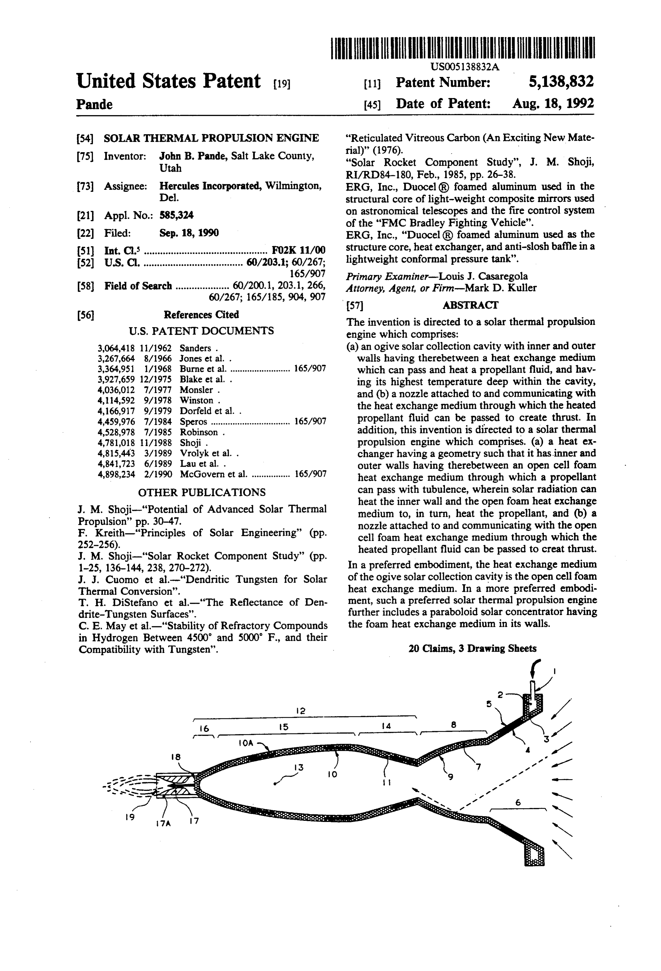
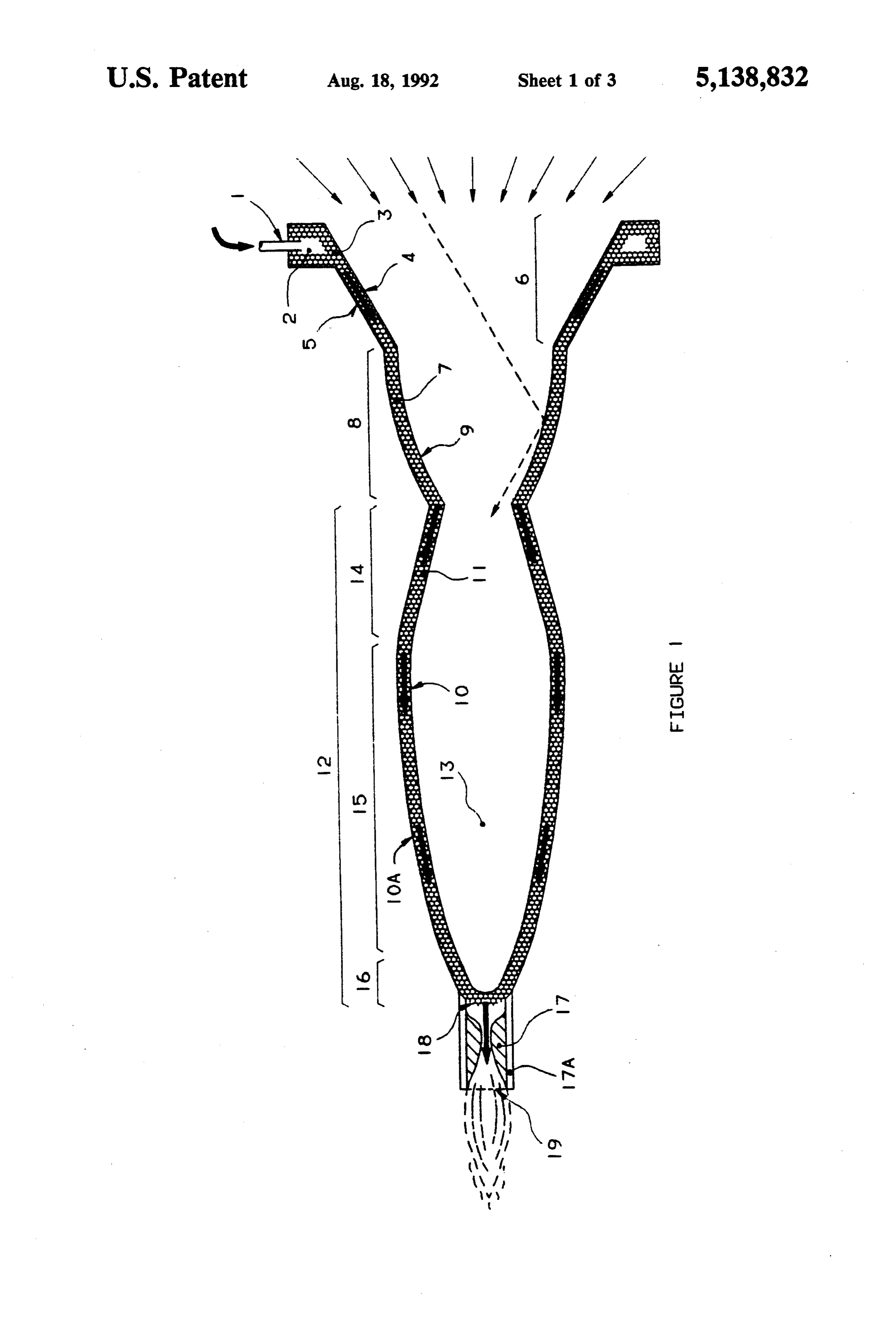
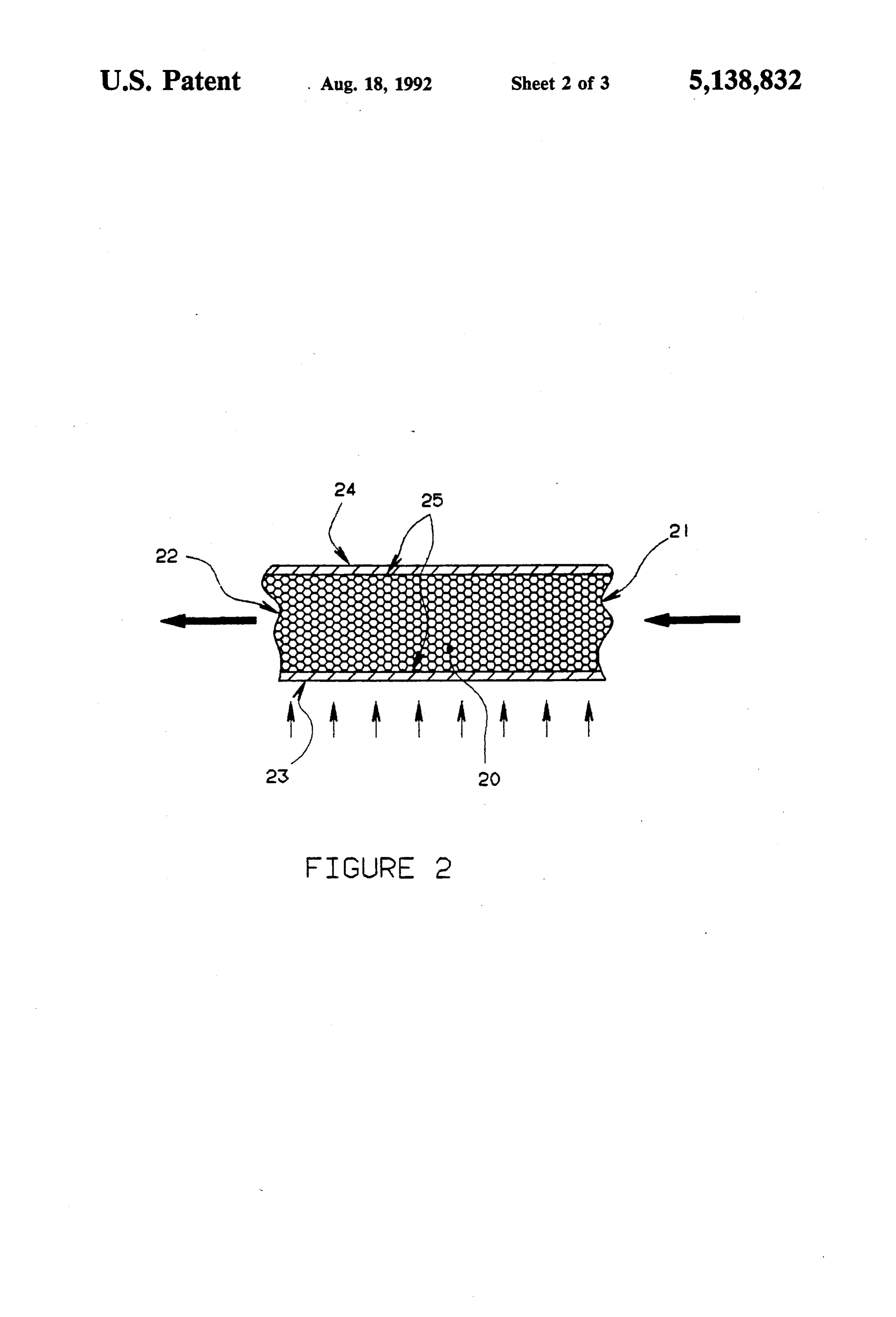
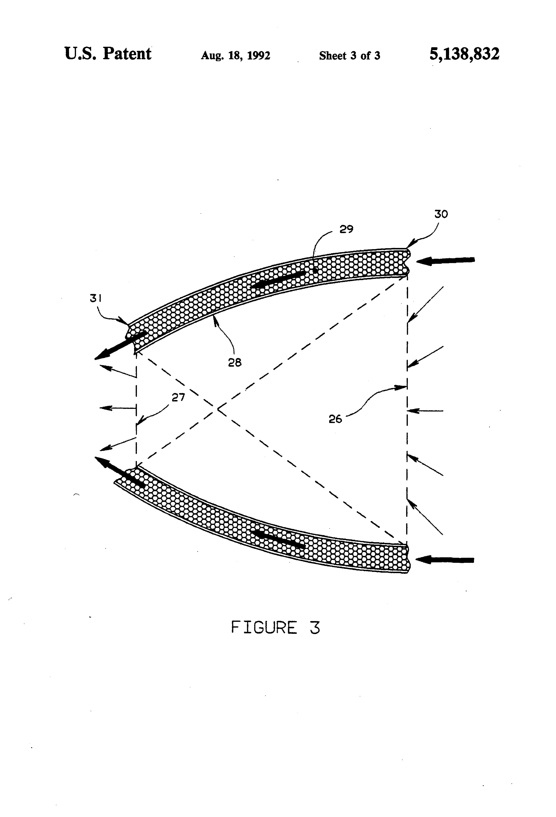
FIG. 1 is a cross-section view of a solar thermal pro lant flow. However, the apex angle formed by its small pulsion device according to the more preferred embodi est and largest aperture can be between 0 degrees and ment of this invention. 180 degrees for cavity optimization, depending on solar FIG. 2 is a partial schematic of the heat exchanger 10 thermal energy apex angle, flux magnitude and distribu which forms the walls of the solar thermal propulsion tion conditions entering the solar thermal propulsion device showing the foam heat exchange medium. device. The ogive 15 has a decreasing aperture in the FIG. 3 is a cross-section view of the regeneratively direction of propellant flow and is preferably a section cooled paraboloid concentrator of the more preferred of a circle. It connects with the entrance aperture 14, embodiment. 15 and connects to closure 16. The closure 16 has a de
DETAILED DESCRIPTION OF THE
creasing aperture which intersects the device's center
INVENTION
line, closing off the cavity.
As solar energy travels deeper into the cavity 13,
This invention is useful with any propellant having inside wall temperatures increase in the direction of high heat capacity and thermal conductivity, and low 20 propellant flow due to the concentrating nature of the molecular weight and viscosity, which is nonreactive cavity and the decreasing regenerative cooling effect of and can achieve a high specific impulse. Preferred are propellant passing through the ogive heat exchange hydrogen, lithium hydride, ammonia and methane, with medium 11. This has the effect of boosting peak temper hydrogen being most preferred. atures and placing the very highest wall surface temper FIG. 1 illustrates a solar thermal propulsion engine 25 atures as far away from the cavity entrance as possible, according to the more preferred embodiment of this reducing re-radiation losses significantly. Efficiency is invention which comprises conical section 6 through also greatly enhanced by the paraboloid concentrator, which solar radiation enters the engine, paraboloid con which effectively reduces the aperture from which centrator section 8 and ogive solar collection cavity 12, radiation within the cavity 13, can escape. all with inner and outer walls having therebetween a 30 Heated propellant leaving the ogive cavity heat ex single-pass open cell foam heat exchange medium, and a change medium 11, enters the converging section of a converging/diverging rocket nozzle 17. converging/diverging rocket nozzle 17, through un Propellant entering through a tube 1 empties into an sealed foam heat exchanger surface 18. Propellant gas annular manifold cavity 2, evenly distributing propel ses are expanded and accelerated through the conver lant about all azimuths of conical section 6 of the en 35 ging/diverging nozzle 17, departing at the rocket noz gine. Propellant then continues into the single-pass, zle exit plane 19 into the vacuum of space. open cell foam heat exchange medium 3 surrounded by FIG. 2 is a partial schematic of the single pass open inner 4 and outer 5 walls. The first section of the contin cell form heat exchanger found in the solar thermal uous single pass heat exchange medium that the propel propulsion device sections 6, 8 and 12. Propellant enters lant encounters is conical section 6. Focused sunlight 40 at 21 and leaves at 22. The high surface area-to-volume (received from a concentrating mirror) enters the large ratio open celled foam 20, provides high conductive and aperture of the conical section 6 through the solar re convective heat exchange rates per unit volume. This is ceiving end of the device. The apex angle of the conical especially important for propellants like hydrogen that section 6 is approximately equal to that of the apex are virtually incapable of absorbing radiant thermal angle of the incoming focused sunlight. Stray sunlight 45 energy directly. The convoluted path the propellant impinging on the conical section 6 inside wall 4 will be takes throught the open cell foam medium promotes absorbed and subsequently raise propellant tempera turbulence, increasing the heat exchange rate. The foam ture. The conical section 6 is regeneratively cooled by porosity is such that it is partially transparent to light, so propellant passing through the heat exchange medium that the inner wall 23 radiantly transmits energy to the 3. outer wall 24 allowing the foam structure to have near Propellant travels through the conical section heat uniform temperature by means of radiant heating. exchange medium 3 and proceeds to the paraboloid Any reticulated solid foam (which may be coated or concentrator heat exchange medium 7 of the paraboloid converted) capable of withstanding the thermal and concentrator section 8. The paraboloid concentrator structural environments of the heat exchanger, and inside surface 9 is optically reflective. Its inside surface 55 compatible with the propellant may be used. Exemplary contour will receive focused and diffuse solar energy are reticulated vitreous carbon (RVC) foam block, and through the aperture of conical section 6, concentrate it, carbide based foam such as hafnium carbide (HfC), and then pass it into the ogive cavity section 12. The zirconium carbide (ZrO), or tantalum carbide (TaC), or paraboloid reflective surface 9 will be regeneratively combinations thereof.
cooled by propellant passing through the underlying 60 Hydrogen compromises the structural integrity of paraboloid heat exchange medium 7. This reduces sur most materials at high temperatures. Therefore, when face temperature-caused re-radiation while recovering hydrogen is the propellant, RVC must be coated with thermal energy that is absorbed. rhenium (Re), hafnium carbide, zirconium carbide, or Propellant leaves the paraboloid concentrator heat other propellant-inert material(s), or converted. RVC is exchange medium 7 and enters ogive cavity heat ex 65 converted by combining it with pure refractory materi change medium 11, which is surrounded by walls 10 als, such as hafnium, to form a carbide. Hafnium carbide and 10A. The ogive section wall 12 encompasses the and zirconium carbide are useful without coating at deep "trapped cavity” 13 where the majority of heat temperatures below about 4840' F. and 4780' F. respec
Page 7
tively, and should be coated with rhenium for use at mentioned methods with the emphasis on reducing higher temperatures. Tantalum carbide reacts with hy overall weight, cost, complexity, and stress-creep rup drogen at lower temperatures than those materials, and ture of the refractory coated surfaces and walls. will normally need to be coated with rhenium to be used An inside rhenium surface finish can be prepared to in the heat exchanger. obtain desirable surface emissivity, absorptivity and The entire open cell heat exchange medium can be reflectivity. Sections 6, 8 and 14 perform best if they fabricated from a single block of foam. (It may be made have high reflectivity and low absorptivity, while sec from more than one piece by connecting parts, e.g., tions 15 and 16 prefer low reflectivity, high emissivity using an adhesive containing foam parent material.) The and high absorptivity. "As deposited' rhenium is typi foam can be machined to the geometrical contour of 10 cally highly reflective, requiring only minor polishing sections 6, 8, and 12. The foam section that forms the to increase its reflectivity to optimum values. Low re annular manifold cavity can be formed by internal re flective surfaces can be created by grit blasting, chemi moval of foam material (e.g., by machining) or by bond cal etching and anodizing. Ion bombardment of a rhe ing a separate piece of foam to the foam heat exchanger nium surface can also create hillock and dendritic sur by an adhesive containing foam parent material. 15 faces that exhibit high absorptivity and high emissivity. For the purpose off nozzle manufacture, inspection, This method is described by T. H. DiStefano et al in and interchangeability with different nozzle sizes and "The reflectance of dendritic-tungsten surfaces', J. geometries, the engine nozzle is preferably interchange Appl. Phys, Vol. 50, No. 6, pp. 4431-35 (1979). able. FIG. 1 shows an interchangeable converging FIG. 3 illustrates the paraboloid concentrator. The diverging nozzle 17, which may be made from a refrac axisymmetric device accepts focused and diffuse solar
tory material or may be made from foam coated with a energy at its largest aperture 26, concentrating and refractory material. It is inserted into nozzle retainer directing solar energy through the small aperture 27 cylinder 17A and electron-beam welded, or otherwise attached and pressure sealed at exit plane 19. The nozzle and into the solar thermal propulsion device cavity. Reflective surfaced diameter walls 28 accomplish this 17 and nozzle retainer cylinder 17A can be formed by 25 task. Surface geometry is derived by rotating a para machining foam and/or solid refractory materials into bolic curve about the desired shape. The nozzle retainer cylinder 17A raboloid; whereby the engine centerline, forming a pa may be directly attached to the heat exchanger 12 by focus solar energy the paraboloid mirrored surface will electron-beam welding, during deposit of refractory of the small aperture 27a region into located along the edge plane, where it intersects the metal, or other methods. Removal of the nozzle 7 is 30 accomplished by grinding off or otherwise breaking the paraboloid inside wall 28. Unreflected solar radiation seal at exit plane 19. Orientation of the nozzle may vary, will pass directly into the ogive cavity 13. The parabo loid geometry is selected to accept incoming solar radi and is shown in FIG. 1 at 0 degree orientation.
In a preferred embodiment, the open cell foam me ation (falling within the apex angle of the outside mirror dium is coated with rhenium by chemical vapor infiltra 35 aperture beam), focused
having no re-reflection out the large
Regenerative cooling of the paraboloid tion (CVI) and, then, pressure containment walls are inside wall 28 is accomplished by heat exchange me formed from rhenium by chemical vapor deposition
(CVD). Rhenium is essentially inert to a hydrogen con dium 29. (If not cooled, surface radiation would effec taining propellant environment, chemically compatible tively cancel benefits realized by the paraboloid con to the underlying carbon or carbide foam structure, centrator.) Relatively cool propellant enters the open very ductile, and exhibits a high service temperature. cell foam heat exchange medium at 30, and passes Once assembled, the foam section is placed in a vacuum through only once before exiting at 31. Solar radiation furnace. Using CVI techniques, rhenium is infiltrated absorbed by the inside reflective surface 28 is trans throughout the foam structure, coating all surfaces. ferred to the propellant, thus regeneratively cooling its surface.
Once the foam is 100% coated, oven temperature, part 45 temperature, and pressure are adjusted to begin the Not shown in the figures are propellant fluid storage CVD process. In the CVD process, rhenium is depos means, solar collection and focusing means, insulation, ited on all outer part surfaces, akin to "skinning' the radiation shields, support structure and means for pre venting sublimation of the inside and outside wall of the part. These outer skinned surfaces form the pressure engine containment walls of the single-pass heat exchanger. 50 cavity.
The outer skinned walls (23 and 24) are integrally and Generally, the propellant fluid will be stored in a tank mechanically attached to the foam structure by penetra compatible with the propellant and transported though tion into the foam outer surface 25. pipes (also not shown) to the solar thermal propulsion An operating heat exchanger is pressurized by pro engine. The tank may be attached to the engine or pay pellant running through it and out the nozzle. Pressur 55 load. Such a tank is shown, for example, in U.S. Pat. No. ization causes mechanical stress in the foam and/or 4,781,018.
outer walls. The structure required to support mechani A solar collection and focusing means or "concen cal stress can be achieved in one or more of the follow trating mirror' (which may be a paraboloid or spheri ing ways: (1) the foam carries all tensile stress between cal) collects solar radiation and focuses it on the solar the walls, while the inner and outer wall are required to thermal propulsion engine. One such device is shown in . provide propellant containment only; (2) a thick metal U.S. Pat. No. 4,781,018. Similar devices, such as graph coating covering the foam carries all tensile stress, ite composite stiffened mirrors, are useful in this inven while the inner and outer walls are required to provide tion and are well known. Preferably, in the embodiment propellant containment only; (3) the inner and outer shown in FIG. 1, the solar radiation is focussed at a walls are thick and support all stresses, while the foam point along the engine centerline, approximately in the is not required to carry any tensile loads; or (4) some middle of paraboloid section 8. FIG. 3 more accurately combination of (1), (2) and (3). Each section of the heat illustrates this location, showing it as the point of inter exchanger may incorporate one or more of the above section of the two diagonal dashed lines.
Page 8
High heat insulating, low heat.conducting, materials thrust vector system to impart pitch and yaw maneu are placed outside the solar thermal engine to prevent vers on the orbital transfer vehicle. heat loss. Reticulated vitreous carbon foam is excellent Two or moe such thermal propulsion engines may be for this purose and may be coated with a material such used in combination, with nozzles at appropriate angles. as hafnium carbide to prevent sublimation. The combination of two or more side by side solar Concentric metal radiation shields will surround the thermal propulsion engines, being supplied by separate hosttest regions of the solar thermal propulsion engine concentrating mirrors, will allow roll maneuvers. to minimize heat loss. These are placed between the While the invention has been described with respect outer walls of the cavity and the foam insulation. to specific embodiments, it should be understood that A support structure ties the solar thermal propulsion 10 they are not intended to be limiting and that many varia engine and its thermal insulation system together. Addi tions and modifications are possible without departing tionally, it forms an interface with or attaches the en from the scope and spirit of this invention. gine to the orbital transfer vehicle structure. The struc What is claimed is:
ture may be as simple as a light weight cylinder that 1. A solar thermal propulsion engine which can re encloses engine and thermal insulation system, and may 15 ceive solar radiation, pass and heat a propellant fluid be equipped with standoffs to attach it to the orbit trans using the solar radiation, and creates thrust which com fer vehicle, a fuel line connector, a thrust vector control prises:
mechanism, etc. (a) a paraboloid solar concentrator having inner and To prevent sublimation of the heated inner wall of the outer walls having therebetween a heat exchange cavity due to exposure to high temperature in a vac 20 medium which can pass and heat a propellant fluid, uum, the cavity is pressurized above the vapor pressure the inner wall being a reflective paraboloid surface of the, e.g., rhenium. This can be done by injecting which can reflect and further focus incoming solar propellant from the cavity wall or pumping propellant radiation within the cavity, the paraboloid solar from the hydrogen storage unit into the cavity. It is also concentrator having its largest aperture at the solar possible to collect nozzle expansion (Prandtl-Meyer) 25 radiation receiving end, gasses leaving the nozzle exit plane that have turned 90 (b) attached to the small aperture end of the parabo degrees or more relative to the engine centerline. These loid solar concentrator, an ogive solar collection gases do not contribute to deliverable specific impulse. cavity with concave inner and outer walls having By means of a scroll (donut shaped collection cavity therebetween a heat exchange medium which can with an annular inlet slit) located just outboard of the 30 pass and heat a propellant fluid, having its highest nozzle exit plane 19, these gasses can be collected and temperatures deep within the cavity, and directed (using piping) inside the cavity, slightly pres (c) a nozzle attached to and communicating with the surizing the local atmosphere to prevent sublimation. heat exchange medium of the ogive solar collection There are oftern small gaps between the outer cavity cavity, through which the heated propellant fluid wall and inermost radiation shield, and outermost radia 35 can be passed to create thrust; tion shield and insulation. The outer cavity wall and the wherein the inner wall of the solar collection cavity, insulation adjacent to the outer cavityu wall are at and the paraboloid solar concentrator can be re nearly the same temperature as the inner cavity wall, generatively cooled by the propellant. and, therefore, it is desirable to pressurize the gaps by 2. A solar thermal propulsion engine as claimed in the outer wall and the insulation to prevent sublimation. claim 1 wherein the heat exchange medium of the ogive This can be done by encasing the outer wall, radiation sollar collection cavity is a single-pass, open cell foam shields and insulation, and pressurizing the volume con through which the propellant can pass with turbulence, tained therein with propellant. wherein solar radiation can heat the inner wall of the The solar thermal engine of FIG. 1 is relatively small ogive solar collection cavity and the open cell foam for its thermal capacity. An engine approximately 1.5 45 heat exchange medium to, in turn, heat the propellant. feet in length has sufficient heat exchanger area to ab 3. A solar thermal propulsion engine as claimed in sorb 50 or more kilowatts of thermal solar power, and claim 1 wherein both the ogive solar collection cavity convert it to kinetic energy in the form of rocket thrust. and the paraboloid solar concentrator have inner and Such a device could propel an orbital transfer vehicle outer walls having therebetween a single-pass, open cell from a low earth orbit (ca. 125 miles altitudee to geosta foam heat exchange medium through which the propel tionary circular orbit (ca. 22,230 mile altitude) in about lant can pass with turbulence, wherein solar radiation two weeks, delivering a payload (such as a communica can heat the inner wall of the ogive solar collection tion satellite) mass about equal to half the low earth cavity and the paraboloid solar concentrator, and the orbit total vehicle starting mass (including propellant). open cell foam heat exchange medium to, in turn, heat For instance, a ca. 450 pound payload and ca. 100 55 the propellant.
pounds of inerts (transfer vehicle, engine, tank, etc.) can 4. A solar thermal propulsion engine which can re be so propelled using ca. 450 pounds of propellant. ceive solar radiation, pass and heat a propellant fluid Tracking the sun with a parabolic mirror, indepen using the solar radiation, and creates thrust which com dent of the orbital transfer vehicle orientation, while prises:
constantly directing solar energy into the cavity entrace (a) a conical section having a large aperture where is very challenging if the solar thermal propulsion en focused solar radiation can enter the engine, gine is rigidly positioned at the mirror focus. Preferably, (b) attached to the small aperture end of the conical the engine is free to translate in three orthogonal coor section, a paraboloid solar concentrator having an dinate planes (X, Y, Z) as well as rotate about these inner reflective paraboloid surface which can re coordinate axes. Translation allows the engine cavity 65 flect and further focus incoming solar radiation entrace to always be correctly positioned at the mirror within the cavity, the paraboloid solar concentra focus, mitigating loss of solar energy due to pointing tor having its largest aperture at the end attached errors of the mirror. Rotation of the engine serves as a to the conical section,
Page 9
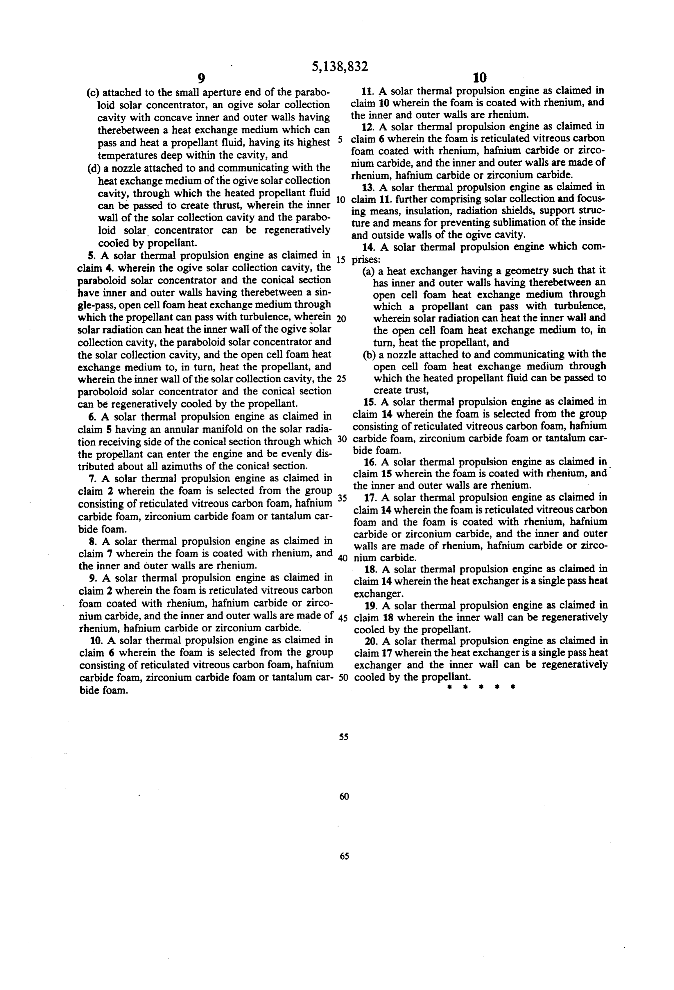
(c) attached to the small aperture end of the parabo 11. A solar thermal propulsion engine as claimed in loid solar concentrator, an ogive solar collection claim 10 wherein the foam is coated with rhenium, and cavity with concave inner and outer walls having the inner and outer walls are rhenium. therebetween a heat exchange medium which can 12. A solar thermal propulsion engine as claimed in pass and heat a propellant fluid, having its highest claim 6 wherein the foam is reticulated vitreous carbon temperatures deep within the cavity, and foam coated with rhenium, hafnium carbide or zirco (d) a nozzle attached to and communicating with the nium carbide, and the inner and outer walls are made of heat exchange medium of the ogive solar collection rhenium, hafnium carbide or zirconium carbide. cavity, through which the heated propellant fluid 13. A solar thermal propulsion engine as claimed in can be passed to create thrust, wherein the inner O claim ing 11. further comprising solar collection and focus means, insulation, radiation shields, support struc wall of the solar collection cavity and the parabo ture and means for preventing sublimation of the inside loid solar concentrator can be regeneratively and outside walls of the ogive cavity. cooled by propellant. 14. A solar thermal propulsion engine which com 5. A solar thermal propulsion engine as claimed in 15 prises:
claim 4. wherein the ogive solar collection cavity, the (a) a heat exchanger having a geometry such that it paraboloid solar concentrator and the conical section has inner and outer walls having therebetween an have inner and outer walls having therebetween a sin open cell foam heat exchange medium through gle-pass, open cell foam heat exchange medium through which a propellant can pass with turbulence, which the propellant can pass with turbulence, wherein 20 wherein solar radiation can heat the inner wall and solar radiation can heat the inner wall of the ogive solar the open cell foam heat exchange medium to, in collection cavity, the paraboloid solar concentrator and turn, heat the propellant, and the solar collection cavity, and the open cell foam heat (b) a nozzle attached to and communicating with the exchange medium to, in turn, heat the propellant, and open cell foam heat exchange medium through wherein the inner wall of the solar collection cavity, the 25 which the heated propellant fluid can be passed to paroboloid solar concentrator and the conical section create trust, can be regeneratively cooled by the propellant. 15. A solar thermal propulsion engine as claimed in 6. A solar thermal propulsion engine as claimed in claim 14 wherein the foam is selected from the group claim 5 having an annular manifold on the solar radia 30 consisting of reticulated vitreous carbon foam, hafnium tion receiving side of the conical section through which carbide foam, zirconium carbide foam or tantalum car the propellant can enter the engine and be evenly dis bide foam.
tributed about all azimuths of the conical section. 16. A solar thermal propulsion engine as claimed in 7. A solar thermal propulsion engine as claimed in claim 15 wherein the foam is coated with rhenium, and claim 2 wherein the foam is selected from the group 35 the17.inner
and outer walls are rhenium.
solar thermal propulsion engine as claimed in consisting of reticulated vitreous carbon foam, hafnium claim 14 wherein the foam is reticulated vitreous carbon carbide foam, zirconium carbide foam or tantalum car foam and the foam is coated with rhenium, hafnium bide foam. carbide or zirconium carbide, and the inner and outer 8. A solar thermal propulsion engine as claimed in walls are made of rhenium, hafnium carbide or zirco claim 7 wherein the foam is coated with rhenium, and nium carbide.
the inner and outer walls are rhenium. 18. A solar thermal propulsion engine as claimed in 9. A solar thermal propulsion engine as claimed in claim 14 wherein the heat exchanger is a single pass heat claim 2 wherein the foam is reticulated vitreous carbon exchanger.
foam coated with rhenium, hafnium carbide or zirco 19. A solar thermal propulsion engine as claimed in nium carbide, and the inner and outer walls are made of 45 claim 18 wherein the inner wall can be regeneratively rhenium, hafnium carbide or zirconium carbide. cooled by the propellant.
10. A solar thermal propulsion engine as claimed in 20. A solar thermal propulsion engine as claimed in claim 6 wherein the foam is selected from the group claim 17 wherein the heat exchanger is a single pass heat consisting of reticulated vitreous carbon foam, hafnium exchanger and the inner wall can be regeneratively carbide foam, zirconium carbide foam or tantalum car 50 cooled by the propellant. k bide foam.
Page 10
UNITED STATES PATENT AND TRADEMARK OFFICE
CERTIFICATE OF CORRECTION
DATED : August l8, l992 Page 1 of 2 INVENTOR(S) : John B. Pande it is certified that error appears in the above-identified patent and that said Letters Patent is hereby corrected as shown below:
On the cover sheet in the Abstract, at line ll, "comprises. (a) should read "comprises: (a)"; Also in the Abstract, at line l5, "tubulence" should read "turbulence";
Col. 2, line 28, "studies" should read "studied"; Col. 4, line l, "solor" should read "solar"; Col. 4, line 38, "form" should read "foam"; Col. 5, line l6, "purpose off" should read
Col. 7, line 34 , "oftern" should read "often"; Col. 7, line 37, "cavityu" should read "cavity"; Col. 7, line 50, "altitudee" should read "altitude"; In the Claims, Col. lo, line lo, "claim ll. " should read "claim ill"; and

Page 11
UNITED STATES PATENT AND TRADEMARK OFFICE
CERTIFICATE OF CORRECTION
DATED August l8, 1992 Page 2 of 2 NVENTOR(S) : John B. Pande
It is certified that error appears in the above-identified patent and that said Letters Patent is hereby corrected as shown below:
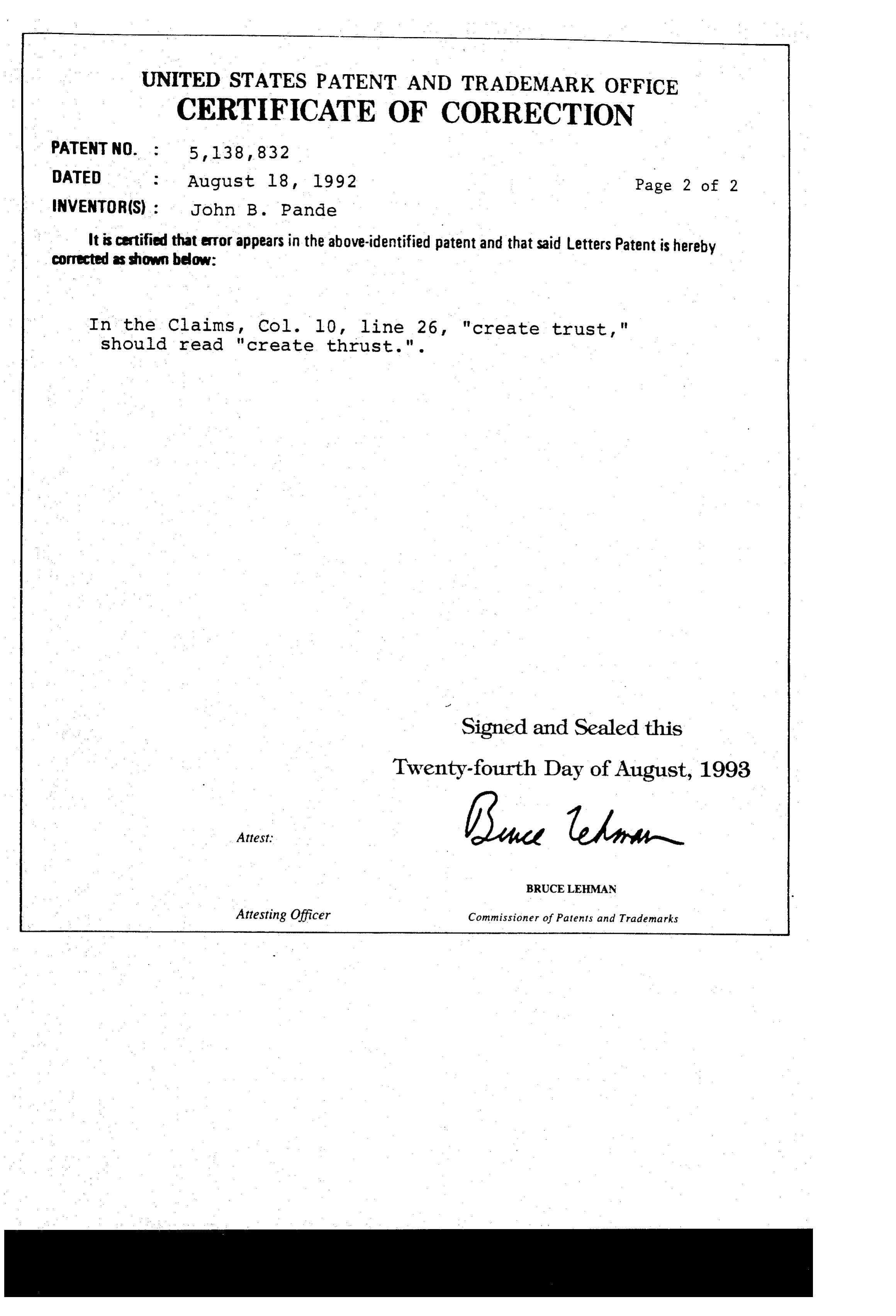
In the Claims, Col. 10, line 26, "create trust," should read "create thrust.".
Signed and Sealed this
Twenty-fourth Day of August, 1993
BRUCELEHMAN
Attesting Officer Commissioner of Patents and Trademarks
Provenance
- Collection
- Cited prior art
- Original PDF
- patentimages.storage.googleapis.com →
- Filed
- 1990-09-18
- Pages
- 11
- Method
- pdftotext (the PDF's own text layer) + pdftoppm 300dpi page scans
- Source
- Google Patents bibliographic record
- Granted
- 1992-08-18
- Inventors
- John B. Pande; Hercules LLC
- Transcribed from
- patentimages.storage.googleapis.com →