patent · US4815443
Solar energy focusing assembly and storage unit
28 March 1989
Page 1 — bibliographic record
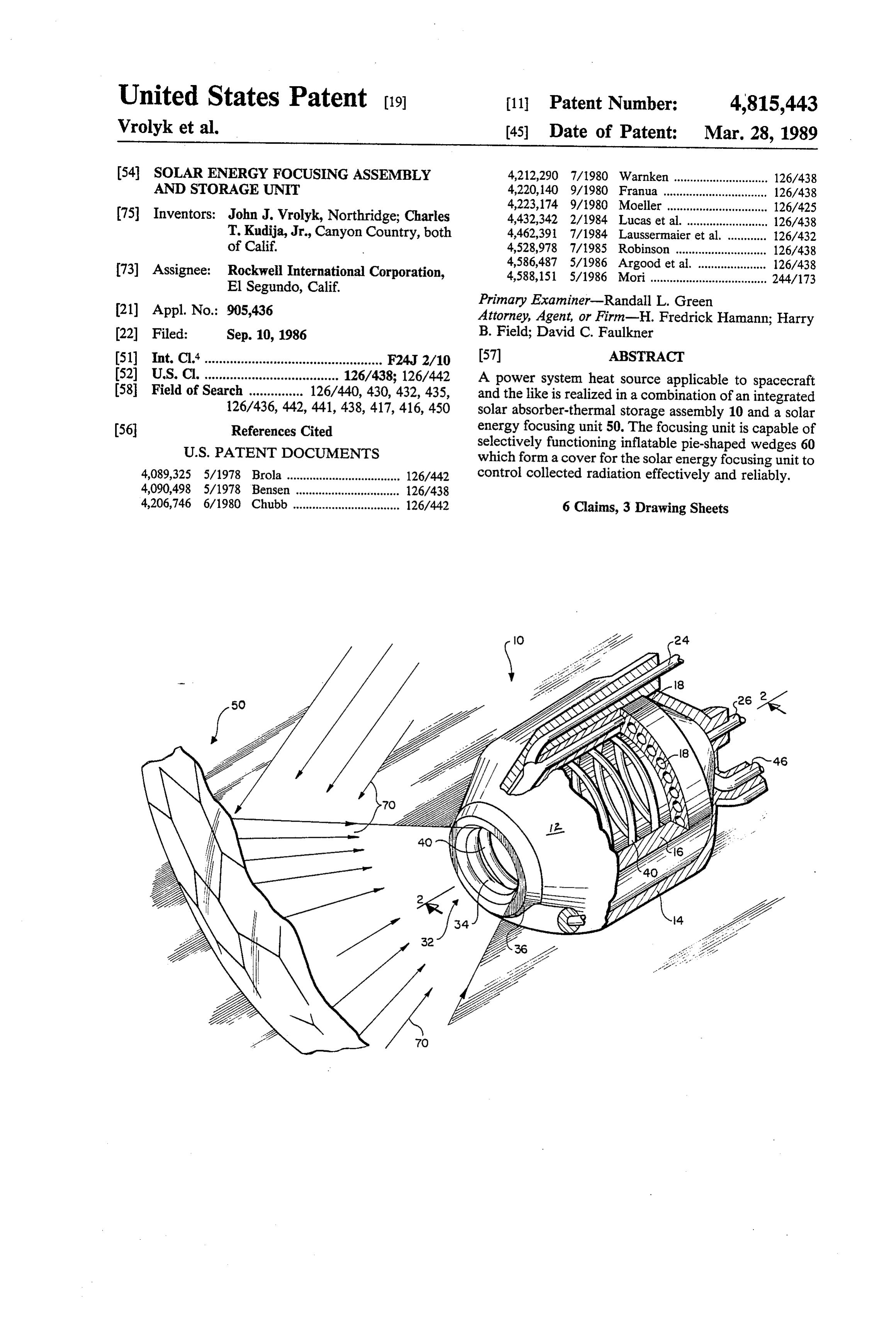
United States Patent (19) 11 Patent Number: 4,815,443 Vrolyket al. (45) Date of Patent: Mar. 28, 1989 54 SOLAR ENERGY FOCUSING ASSEMBLY 4,212,290 7/1980 Warnken ............................. 126/438 AND STORAGE UNIT 4,220,140 9/1980 Franula ... ... 126/438 4,223,174 9/1980 Moeller ...... ... 126/425 (75) Inventors: John J. Vrolyk, Northridge; Charles 4,432,342 2/1984 Lucas et al. ......................... 126/438 T. Kudija, Jr., Canyon Country, both 4,462,391 7/1984 Laussermaier et al. ... 126/432 of Calif. 4,528,978 7/1985 Robinson ................ ... 126/438 4,586,487 5/1986 Argood et al. . ... 126/438 (73) Assignee: Rockwell International Corporation, 4,588,151 5/1986 Mori .................................... 244/173 El Segundo, Calif. Primary Examiner-Randall L. Green (21) Appl. No.: 905,436 Attorney, Agent, or Firm-H. Fredrick Hamann; Harry 22 Filed: Sep. 10, 1986 B. Field; David C. Faulkner 51) Int. Cl."................................................. F24J 2/10 (57) ABSTRACT 52 U.S. Cl. ..................................... 126/438; 126/442 A power system heat source applicable to spacecraft 58 Field of Search ............... 126/440, 430, 432, 435, and the like is realized in a combination of an integrated 126/436, 442, 441, 438, 417, 416, 450 solar absorber-thermal storage assembly 10 and a solar energy focusing unit 50. The focusing unit is capable of (56 References Cited selectively functioning inflatable pie-shaped wedges 60
4,089,325 5/1978 Brola ................................... 126/442 control collected radiation effectively and reliably. 4,090,498 5/1978 Bensen ................................ 126/438 4,206,746 6/1980 Chubb ................................. 126/442 6 Claims, 3 Drawing Sheets
Page 2
Drawing sheet — no readable text.
Page 3
Drawing sheet — no readable text.
Page 4
Drawing sheet — no readable text.
Page 5
These and other objects and features of the present
SOLAR ENERGY FOCUSING ASSEMBLY AND invention will be apparent from the following detailed STORAGE UNIT description when considered in connection with the accompanying drawings.
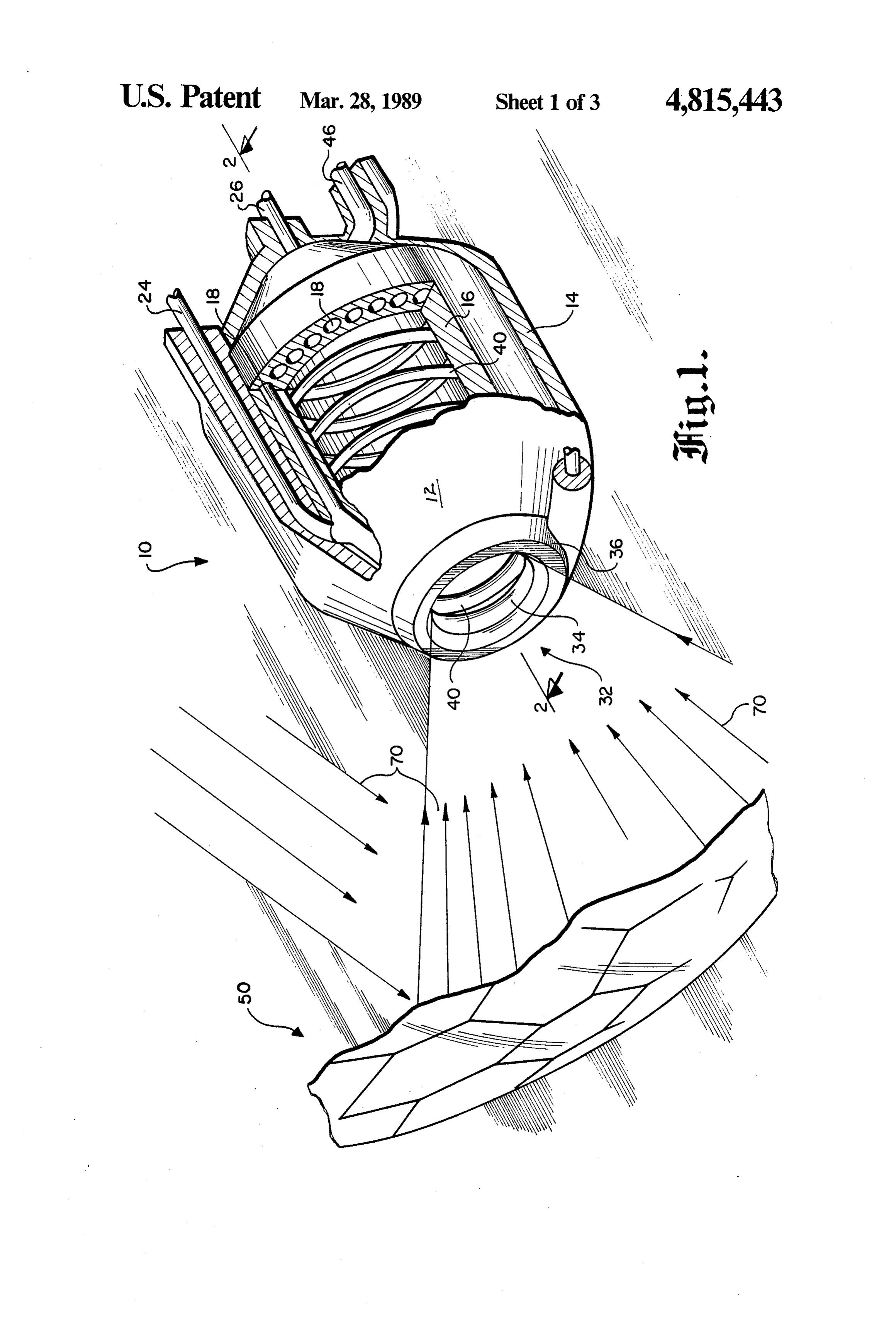
1. Technical Field BRIEF DESCRIPTION OF THE DRAWINGS The present invention relates generally to a solar FIG. 1 is a perspective, partially schematic view of dynamic method for utilizing solar energy to supply the combined solar energy focusing assembly and stor power to a space station. More specifically, this inven 10 age unit; a cutaway of the storage unit is provided to tion is directed to a combined integrated solar absorber show internal details.
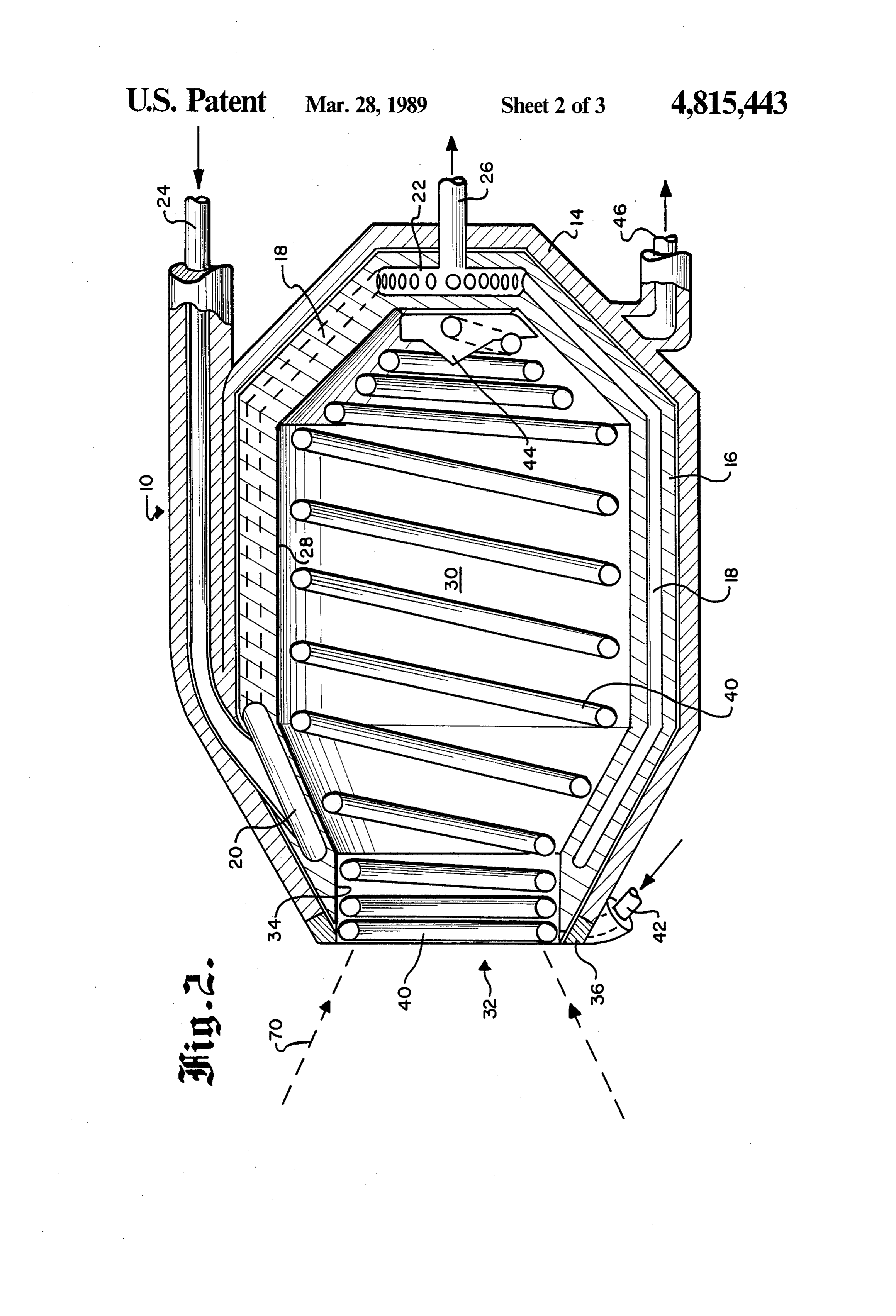
thermal storage assembly and a solar energy focusing FIG. 2 is a cross section of the storage unit taken unit. along line 2-2 of FIG. 1, detailing the dual fluid heat 2. Background Art ing conduit arrangement.
Various solar radiation concentrators or collectors 15 FIG. 3 is a top view of the interior heat shield located have previously been proposed to meet electrical power within the storage unit.
or propulsion requirements of spacecraft, satellites and FIG. 4 is a side view of the interior heat shield taken the space station project. One such solar ray collector along line 3-3 of FIG. 3.
for use with a spacecraft utilizes posts extending respec FIG. 5 is a partial schematic of the solar energy fo tively from apexes of a hexagon and collector subassem 20 cusing assembly of the present invention. blies, each having a light receiving surface substantially DETAILED DESCRIPTION identical in shape with the hexagon, as disclosed in U.S.
Pat. No. 4,588,151, to Mori dated May 13, 1986. Referring now to the drawings and more particularly A solar rocket absorber for use in outer space that to FIG. 1, there is shown an integrated or combined heats a liquid by v solar energy and outputs the heated 25 solar absorber-thermal storage assembly and solar en fluid to a thruster is disclosed in U.S. Pat. No. 4,528,978 ergy focusing unit 10 and 50, respectively. The focusing to Robinson dated July 16, 1985. unit and storage assembly are aligned and integrally Historically, thermal storage devices have utilized connected by a truss support structure (not shown). the same fluid for charging the thermal storage media This allows the solar energy focusing unit to controlla up to a high temperature and for subsequently extract 30 bly direct solar energy to the solar energy absorber ing the heat with the same fluid. thermal storage assembly.
In contrast, the thermal storage assembly of the pres As best seen in FIGS. 1 and 2, the solar energy ab ent invention charges the assembly by direct solar radia sorber-thermal storage assembly 10 includes a housing tion and subsequently extracts the stored heat from the 12 of generally oval configuration. The housing is pro assembly utilizing a separate heat transfer fluid. 35 vided with a high temperature multifoil layer of outer DISCLOSURE OF THE INVENTION insulation 14. The outer multifoil insulation layer may be constructed of metals capable of taking a high polish
The present invention provides a solar energy focuse such as nickel, aluminum, stainless steel, gold, silver and ing assembly and storage unit which may be utilized in platinum or a combination of these metals. Primary functional cooperation with a space station power sup 40 consideration for metal selection is light weight and the ply heat engine. ability to withstand the operating temperatures. When a space station is in a typical low earth orbit, it An inner thermal energy storage layer 16 is mated to passes through the shadow of the earth. During this the outer insulation layer 14 as by welding, pinning or shadowed period, the heat engine must be supplied with bonding. The inner thermal energy storage layer is stored heat so that electrical output from the heat en 45 made of a metallic material, preferably beryllium or the gine will not be interrupted. salts thereof, which are capable of withstanding temper The solar energy focusing assembly includes a reflec atures up to about 1300 C. This inner thermal storage tive parabolic mirror and functional iris mirror surface material layer conforms to the generally oval shape of cover assembly for concentrating and directing solar the outer insulation layer. Retained within the inner radiation to a thermal storage unit having dual fluid 50 thermal storage material layer is a network of fluid conduit systems configured to be selectively heated by conduits 18 positioned radially and circumferentially incident solar radiation or passively by heat stored in therein along the axial length of the housing 12. the insulated body housing of the thermal storage unit. The fluid conduit network is functionally associated This assembly is thus capable of providing heated fluid with a circumferential inlet manifold 20 at which the to the space station heat engine at a continuous rate both 55 network of fluid conduits connect and emanate, and a during the in-sun and in-shadow time periods. circular outlet manifold 22 at which the network of It is an object of the present invention to provide an fluid conduits juncture and terminate. integrated solar absorber-thermal storage assembly and The fluid conduit network 18, including the circum a solar energy focusing unit. ferential inlet manifold and circular outlet manifold, all Another object of the present invention is realized positioned within the inner thermal energy storage with a solar absorber-thermal storage assembly config layer, is also equipped with a fluid inlet 24 and fluid ured to provide thermal energy to a heated fluid pow outlet 26 in functional association with the inlet mani ered heat engine. fold and outlet manifold respectively. The fluid conduit Yet another object of the present invention is to pro network including all the cofunctioning components vide a solar energy focusing unit in cooperative associa 65 may be constructed of thin-walled stainless steel, or tion with the solar absorber-thermal storage, the focus nickel-base alloys such as Hastelloy (Trademark of ing unit having a unique iris mirror surface cover assem Union Carbide Corporation) and refractory material bly. such as niobium and zirconium.
Page 6
The housing 12 of the storage assembly 10, and par vidually or concurrently through a control valve and ticularly the inner wall surface 28 of the inner thermal manifold 62, with either gas or air being delivered to the energy storage layer 16 defines an inner cavity 30. A control valve through a line from a compressor or solar radiation admitting circular aperture 32 is formed pump. The gas or air may be controllably exhausted within one end of the housing opposite the fluid conduit from wedges 60 individually or concurrently through network outlet manifold 22 and fluid outlet 26. Formed an electrically operated discharge valve, typically of integrally with the housing at the terminus of the outer the solenoid type, which may be opened and closed by composite insulation layer and the inner thermal energy electrical signals. A sensor or sensors positioned so as to layer proximate the opening of the housing aperture 32 be engaged by the inflatable wedge segments are cou and rim 34 is a generally circular thermal insulation ring 10 pled to an automatic control monitor. This control mon 36 made of, for example, aluminum oxide. itor responds to actuation of a sensor and automatically Referring now to FIG. 2, there is shown an indepen energizes alternatively a pump or discharge valve to dent helical-shaped fluid conduit assembly 40 contained supply gas or discharge same from a wedge segment, as and seated within the inner housing cavity. 30 and aper necessary to continuously optimize the surface area of ture opening rim 34. The coiled fluid conduit assembly 15 the reflective mirror surface for concentrating collected may be made of the same material referred to above for solar radiation effectively and reliably at essentially a the fluid conduit network 18 and associated structures single focal point, the aperture of the solar absorber located within the inner thermal storage material layer thermal storage assembly.
16. In operation, a high temperature heat transfer fluid The helical-shaped fluid conduit assembly 40 con 20 such as lithium, sodium or sodium potassium or a high tained within the inner cavity is constrained in its mo temperature oil is utilized to transfer heat from the solar tion relative to the outer wall surface of the inner ther absorber to the heat engine during the in-sun time per mal energy storage layer at a multiplicity of select at iod and from the thermal storage layer of the solar tachment points. The fluid conduit assembly 40 thereby absorber-thermal storage assembly to the heat engine forms a fluid conduit network having a tightly coiled 25 during the in-shadow time period.
configuration within the housing at the aperture and As the combined solar absorber-thermal storage as opposite end thereof, and spaced further apart the sembly and solar energy focusing unit, which is posi reinbetween to allow admitted solar energy to impinge tioned on the space station platform, emerges from the not only on the helical-shaped fluid conduit assembly shadow of the earth, the parabolic reflective mirror but also upon portions of the outer wall surface of the 30 surface concentrates and focuses solar radiation at the inner thermal energy storage layer. aperture of the solar absorber-thermal storage assembly The helical-shaped fluid conduit assembly 40 is also housing. The solar radiation (indicated by arrows 70) equipped with a fluid inlet 42 proximate the housing enters the housing cavity where it impinges upon both aperture 32 which connects to the assembly and a fluid the helical-shaped fluid conduit assembly and the wall outlet 46 at the end of the housing cavity opposite the 35 surface 28 of the inner thermal storage layer 16 therein. aperture 32 (see FIGS. 1, 3 and 4). A conical terminus During the in-sun period the helical-shaped fluid con 44 acts as a heat shield to protect the juncture of the duit assembly is selectively engaged, such as by appro fluid conduit assembly 40 and fluid outlet 46 from expo priate valves, pumps and associated monitoring and sure to direct solar radiation which impinges upon the control equipment.
conical terminus and outer wall surface of the inner The high temperature fluid within the helical-shaped thermal energy storage layer associated therewith. fluid conduit assembly is heated by the solar radiation Turning now to FIG. 5, the solar energy focusing and channeled directly to fluid outlets which discharge unit 50 is shown in greater detail. The solar energy into an expansion tank in a closed loop configuration focusing unit includes a truss support structure 52, re coupled to a heat exchanger (not shown). The heat flective parabolic mirror 54 and surface 56, and a func 45 exchanger transfers the heat form the working fluid to a tional iris mirror surface cover assembly 58 for selec heat engine or prime mover such as a Brayton cycle. tively controlling the collection and concentration of The heat depleted fluid is cycled back to the solar ab solar radiation at the thermal storage assembly 10. sorber and the process repeated. More particularly, the solar mirror surface iris cover Concurrently, while the helical-shaped fluid conduit assembly 58 comprises a multiplicity of flexible, imper 50 assembly is in operation, a fraction of the sunlight passes meable functionally interconnected pie-shaped extensi between the helical turns of the helical-shaped fluid ble and retractable inflatable wedges 60 and a gas mani conduit assembly and strikes the outer wall surface of fold 62 divided into independent compartments 64, at the solid beryllium inner thermal energy storage layer the outermost perimeter of the mirror surface and inter which absorbs heat from the solar radiation. The connected to a gas delivery system (not shown) associ 55 amount of heat absorbed by the beryllium is purposely ated with the cover assembly. These flexible pie-shaped varied along the outer wall surface by selectively vary wedges forming the iris cover may be constructed of ing the space between the coils of the helical-shaped any suitable material having the desired flexibility, im fluid conduit assembly. In so doing, the temperature of permeability and capability of withstanding the rigors the beryllium storage layer is raised to a high and ap of the space environment. Materials suitable for the 60 proximately uniform level at the end of the in-sun per wedge construction would be polymers such as Myler iod.
(Trademark for film of polyethylene terephthalate-E. At the beginning of the in-shadow period, the work I. du Pont de Nemours & Co., Inc.) which has been ing fluid within the helical-shaped fluid conduit assem precoated with a thin layer of aluminum, silver or gold bly no longer receives heat from sunlight and that sys metal. 65 tem is shut down by the associated monitoring and A gas delivery system (not shown) is also provided control equipment (not shown) with the concurrent by which air or other gases such as nitrogen or helium rechanneling of fluid through the network of fluid con may be selectively introduced into the wedges 60 indi duits retained within the beryllium storage layer. This
Page 7
will cause a thermocline to occur and to travel from the surfaces for focussing sun rays attached to said housing aperture end at manifold 20 to the circular support structure, and a functional iris mirror sur outlet manifold 22 at which the network of fluid con face cover assembly for covering said mirrors and duits juncture and terminate. The geometry and thermal surfaces comprising a multiplicity of flexible, im time constant of the inner thermal storage layer are permeable functionally interconnected pie-shaped selected such that the travel time of the thermocline extensible and retractable inflatable wedges for approximately equals or exceeds the length of time the selectively controlling the collection and concen space station is in the shadow period. tration of solar radiation at the thermal storage The thermal storage material properties, geometry assembly.
and the thermal and fluid dynamic properties of the 10 2. The combination of claim 1 in which the outer liquid and rate of heat removal are all selected so that composite insulation layer comprises multi-foil metallic when the space station is reentering the in-sun phase of layers selected from the group of metals consisting of the orbit, the thermocline is at a prescribed position stainless steel, aluminum, gold, silver, platinum and along the axial length of the storage layer. nickel.
The process described above is then repeated during 15 3. The combination of claim 1 in which the inner each successive orbit. thermal energy storage layer further includes a circum Obviously, many modifications and variations of the ferential inlet manifold at which the network of fluid present invention are possible in light of the above conduits connect and emanate, a circular outlet mani teachings. It is therefore to be understood that, within fold at which the network of fluid conduits juncture and the scope of the appended claims, the invention may be 20 terminate, and a fluid inlet and fluid outlet in functional practiced otherwise than as specifically described. association with the inlet manifold and outlet manifold, What is claimed and desired to be secured by Letters respectively.
Patent of the United States is: 4. The combination of claim 1 in which a generally 1. In combination, an integrated solar absorber-ther circular thermal insulation ring is connected at the ter mal storage assembly and a solar energy focusing unit in 25 minus of the outer composite insulation layer and the which the storage assembly comprises: inner thermal energy storage layer proximate the open (a) a housing of a generally oval configuration com ing of the housing aperture.
prising: 5. The combination of claim 1 in which the shaped (1) an outer composite insulation layer; fluid conduit assembly includes a multiplicity of select (2) an inner thermal energy storage layer conform 30 attachment points within the housing cavity which ing to the configuration of the housing and outer form a fluid conduit network having a tightly coiled insulation layer, said inner storage layer further configuration within the housing at the aperture and comprising a network of fluid conduits retained opposite end thereof, and spaced further apart the within the inner thermal storage layer and posi reinbetween to allow admitted solar energy to impinge tioned radially and circumferentially in confor 35 not only on the shaped fluid conduit assembly but also mity with the shape of the energy storage layer; upon the inner wall surface of the inner thermal energy (3) an inner cavity formed by an inner wall surface storage layer.
of the inner thermal energy storage layer; 6. The combination of claim 5 in which the shaped (4) a solar radiation admitting circular aperture fluid conduit assembly further includes a fluid conduit formed within one end of the housing; terminus interconnected to a fluid outlet at the end of (5) a shaped fluid conduit assembly contained the housing cavity opposite the aperture, and a shaped within the inner cavity and aperture; and fluid conduit assembly fluid inlet at the aperture end of (b) the solar energy focusing unit includes a truss the housing.
support structure, reflective parabolic mirrors and k is k
Provenance
- Collection
- Cited prior art
- Original PDF
- patentimages.storage.googleapis.com →
- Filed
- 1986-09-10
- Pages
- 7
- Method
- pdftotext (the PDF's own text layer) + pdftoppm 300dpi page scans
- Source
- Google Patents bibliographic record
- Granted
- 1989-03-28
- Inventors
- John J. Vrolyk; Charles T. Kudija, Jr.; Rockwell International Corp
- Transcribed from
- patentimages.storage.googleapis.com →