patent · US6162049
Premixed ionization modulated extendable burner
19 December 2000
Page 1 — bibliographic record
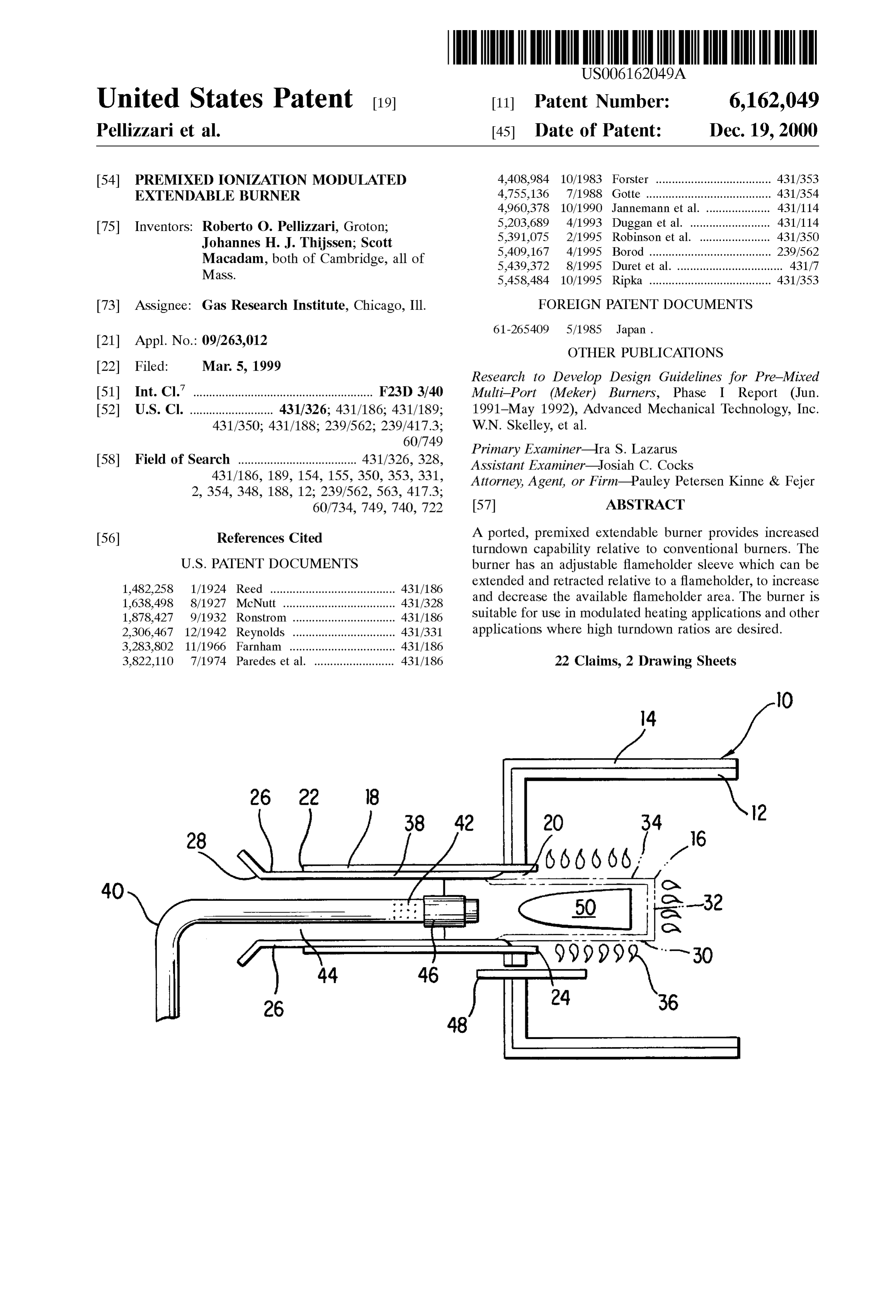
United States Patent (19) 11 Patent Number: 6,162,049 Pellizzari et al. (45) Date of Patent: Dec. 19, 2000 54 PREMIXED IONIZATION MODULATED 4,408,984 10/1983 Forster .................................... 431/353 EXTENDABLE BURNER 4,755,136 7/1988 Gotte .................. ... 431/354 4,960,378 10/1990 Jannemann et al. .................... 431/114 75 Inventors: Roberto O. Pellizzari, Groton; 5,203,689 4/1993 Duggan et al. ......................... 431/114 Johannes H. J. Thijssen; Scott 5,391,075 2/1995 Robinson et al. ...................... 431/350 Macadam, both of Cambridge, all of 5,409,167 4/1995 Borod ...................................... 239/562 Mass. 5,439,372 8/1995 Duret et al. ................................. 431/7 5,458,484 10/1995 Ripka ...................................... 431/353 73 Assignee: Gas Research Institute, Chicago, Ill. FOREIGN PATENT DOCUMENTS
OTHER PUBLICATIONS
22 Filed: Mar. 5, 1999 Research to Develop Design Guidelines for Pre-Mixed (51) Int. Cl." ........................................................ F23D 3/40 Multi-Port (Meker) Burners, Phase I Report (Jun. 52 U.S. Cl. .......................... 431/326; 431/186; 431/189; 1991-May 1992), Advanced Mechanical Technology, Inc. 431/350; 431/188; 239/562; 239/417.3; W.N. Skelley, et al.
Primary Examiner Ira S. Lazarus 58 Field of Search ..................................... 431/326, 328, ASSistant Examiner Josiah C. Cocks 431/186, 189, 154, 155, 350, 353, 331, Attorney, Agent, or Firm-Pauley Petersen Kinne & Fejer
60/734, 749, 740, 722 57 ABSTRACT 56) References Cited A ported, premixed extendable burner provides increased turndown capability relative to conventional burners. The
1,482,258 1/1924 Reed ....................................... 431/186 extended and retracted relative to a flameholder, to increase and decrease the available flameholder area. The burner is 1,638.498 8/1927 McNutt ... ... 431/328 1878,427 9/1932 Ronstrom ..... ... 431/186 Suitable for use in modulated heating applications and other 2,306.467 12/1942 Reynolds ... ... 431/331 applications where high turndown ratios are desired. 3,283,802 11/1966 Farnham .......... ... 431/186 3,822,110 7/1974 Paredes et al. ......................... 431/186 22 Claims, 2 Drawing Sheets
Page 2
Drawing sheet — no readable text.
Page 3
Drawing sheet — no readable text.
Page 4
PREMIXED ONIZATION MODULATED expansion of the flameholder, yet insufficient to permit a EXTENDABLE BURNER flame to burn between the inner and outer tubes. In other words, the Spacing between the tubes is Small or Substan
FIELD OF THE INVENTION tially nonexistent. This way, the only area of the flameholder tube which may Support a flame is on the part of the ported
This invention is directed to a gas burner having an flameholder that extends beyond the outlet end of the outer adjustable firing Surface area, which can operate over a wide tube. This area is adjustable by moving either the inner or range of firing rates while maintaining low levels of air outer tube relative to the other, to provide larger and Smaller pollutant emissions. flames.
BACKGROUND OF THE INVENTION 1O A gas injection manifold located inside the inner tube carries natural gas, or another combustible gas, from a
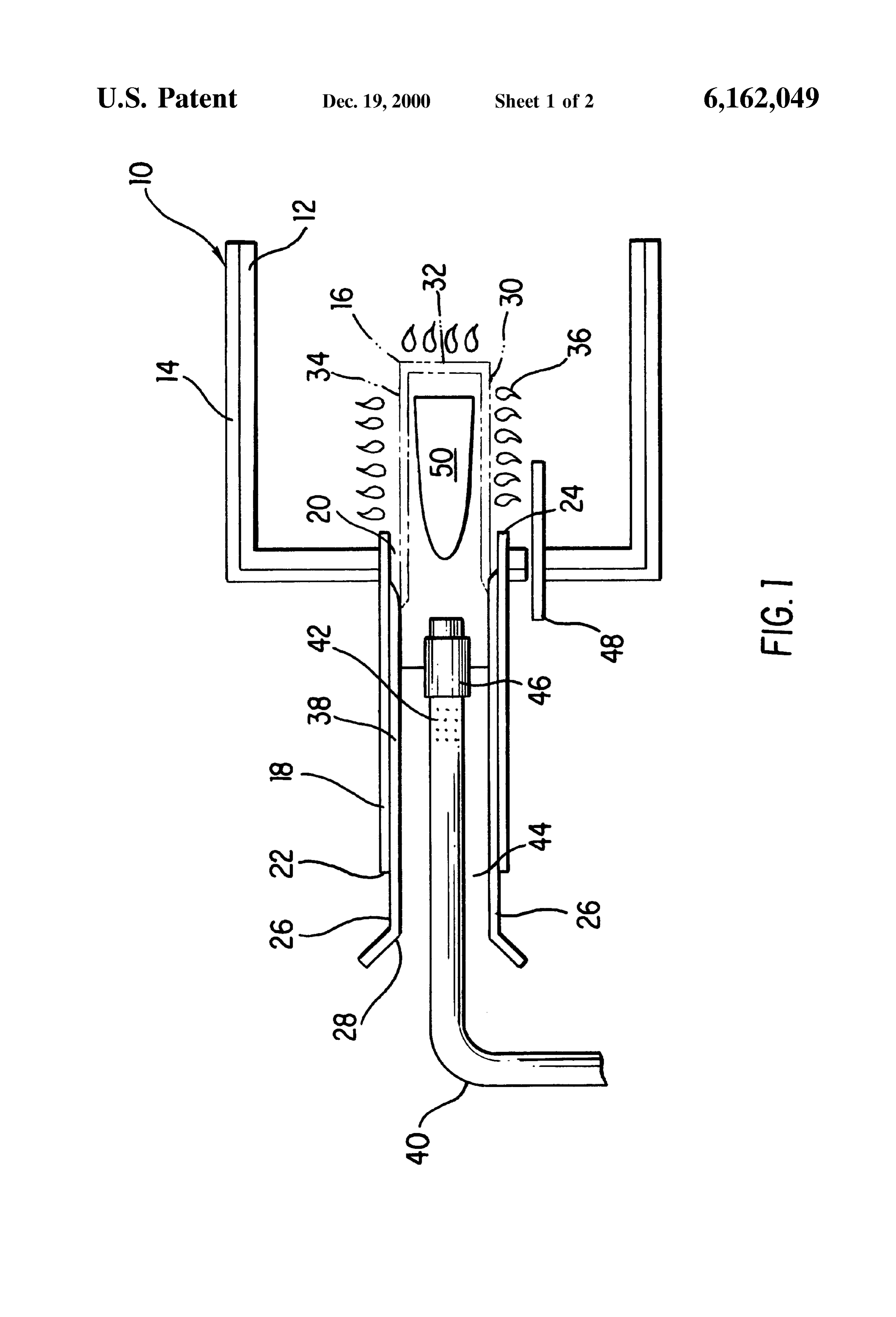
The “turndown” ratio or capability of a burner is the ratio Supply Source to a location upstream from the outlet of the of its maximum firing rate to its minimum firing rate. outer tube and the exposed part of the ported flameholder. Conventional ported premixed burnerS operating at fixed An air flow channel is located between the inner Surface of stoichiometry have a turndown capability of about 6:1. This 15 the inner tube and the outer Surface of the gas injection ratio is generally governed by the flame Speed of the manifold. The air flow channel carries combustion air which particular fuel/air mixture, the flow Velocity through the mixes with the combustible gas leaving the gas injection ports, the recirculation characteristics of the flow field manifold, at a desired predetermined ratio. immediately downstream from the ports, and the heat trans BRIEF DESCRIPTION OF THE DRAWINGS fer characteristics of the system. If the relationship between these variables becomes out of balance, the result may be FIG. 1 schematically illustrates the extendable premixed lifting or flashback. Upsets in the air/fuel ratio lead to burner of the invention, connected to a furnace housing. increased emission of carbon monoxide, nitrous oxides, FIG. 2 illustrates a presently preferred pattern for port hydrocarbons, and other pollutants.
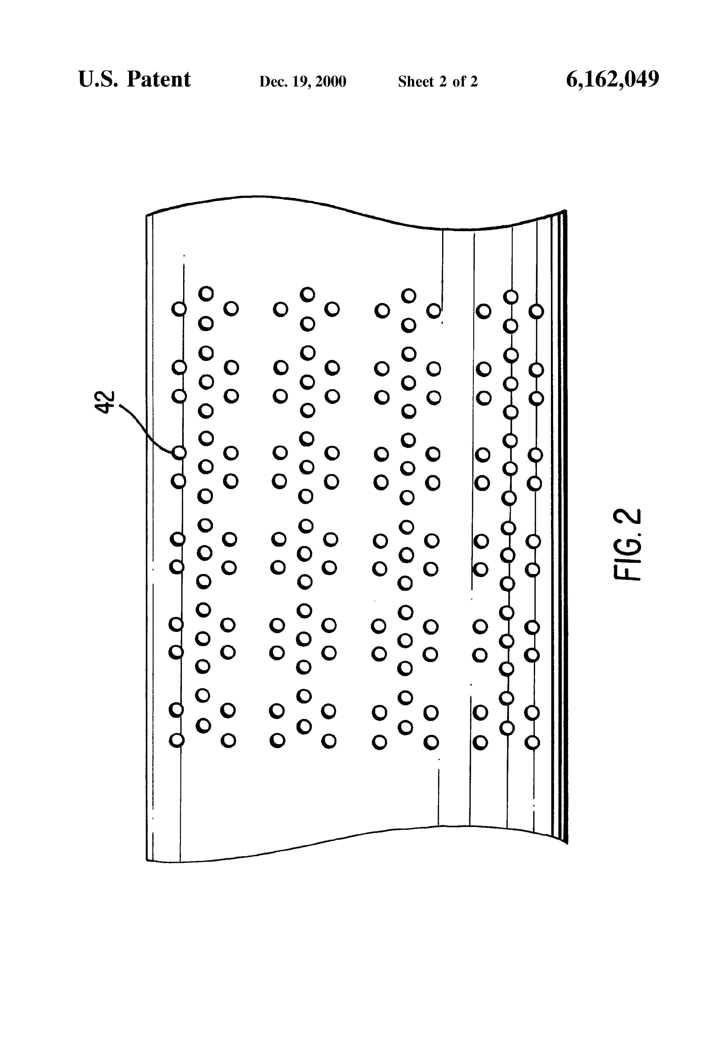
Burners are also employed in direct-fired make-up air openings on the burner flameholder.
furnace units. The burners are typically inserted into a 25 DETAILED DESCRIPTION OF THE make-up air duct or cabinet in a position upstream from an PRESENTLY PREFERRED EMBODIMENTS air blower. A portion of a make-up air Stream is drawn into the burner(s) and enters a region where it is mixed with fuel an Referring to FIG. 1, part of a shroud 10 is shown, having insulation layer 12 and a housing 14. A flame is Stabilized injected through a manifold. The air/fuel ratio is chosen to minimize the emission of pollutants. The combustible mix on the Surface of an extendable premix burner 16 contained ture flows through a perforated plate which acts as a flame within the shroud 10. The premix burner 16 includes an stabilizer. The hot combustion products then mix with outer housing duct 18 which is axially movable relative to a bypass air, providing direct heat to the main air Stream. flameholder portion 30 and shroud housing 14. Outer duct 18 is preferably tubular, and mounted around an inner duct
In order to increase the flexibility of premixed burners, to 26.
permit their operation over a wider range of temperatures 35 remote The outer housing duct 18 has an inlet end 22 which is and conditions, there is a need or desire for burners having just inside from opening 20, and an outlet end 24 which extends higher turndown ratioS that generate minimal quantities of Structed of aopeningSolid 20. The outer housing duct 18 is con (i.e., non-perforated) material, which can pollutants. be Steel or a high temperature-resistant ceramic. SUMMARY OF THE INVENTION The burner 16 also includes an inner duct 26 which is 40 preferably tubular, and which is fixed with respect to the
The present invention is directed to an extendable pre Shroud housing 14. The Outer duct 18 may slidably engage mixed burner having a higher turndown capability while the inner duct 26, or may rotatably engage the inner duct 26 operating at fixed Stoichiometry. The higher turndown capa via a threaded connection. If the inner and Outer ducts bility is accomplished by providing the burner with a ported Slidably engage each other, the Outer duct 18 may be pushed flameholder having an adjustable open area. By varying the 45 and pulled relative to the inner duct 26 by any suitable area of the flameholder, the amount of heat generated can be means, including without limitation the use of a plunger increased or decreased to a greater extent than is possible connected to a first end 22 of outer duct 18 and associated using conventional burners having fixed flameholder areas. with a linear actuator. If the inner and Outer ducts are The burner can be used in furnaces, proceSS heaters, turbine rotatably engaged using a threaded connection (e.g., using engines, and other appliances which employ premix or 50 threads on the outer Surface of inner duct 26 and engaging partially premix burners. complementary threads on the inner Surface of outer duct The burner of the invention includes a Solid (i.e., non 18), then the outer duct 18 may be driven forward and perforated) outer housing tube having an inlet end and an backward, and Simultaneously rotated, using a gear and outlet end. In a first embodiment, the outer housing tube may motor assembly or another Suitable rotating mechanism. be movable with respect to a burner shroud. In this 55 The inner duct 26 includes a perforated flameholder embodiment, the inner tube is fixed with respect to the outer portion 30 at a second end 32 thereof The flameholder housing tube. In a Second embodiment, the position of the portion 30 includes a plurality of Small openings 34 on and outer housing tube may be fixed with respect to the burner around the outer surface of the duct. The openings 34 feed shroud. In this embodiment, an inner tube is movable back a flame 36 by carrying a combustible mixture of fuel gas and and forth with respect to the outer housing tube. air from the inside of the duct 18, and outward through the In both embodiments, the inner tube has a perforated openings 34. The fuel gas may be a hydrocarbon gas,
Section which Serves as a ported flameholder, and which another organic fuel gas, or an inorganic fuel gas Such as extends beyond the outlet end of the outer housing tube (for hydrogen.
example, into a furnace or other appliance). The inner tube A presently preferred flameholder has a 8-15% open area, also has a Solid (non-perforated) portion which does not with openings about 0.01-0.05 inch in diameter. The open extend beyond the outlet of the outer housing tube. 65 area may range from about 5-25% in different embodiments, The spacing between the inner flameholder tube and the with openings ranging from about 0.01-0.10 inch in diam outer housing tube is Sufficient to accommodate thermal eter. Depending on the axial position of the Outer duct 18
Page 5
relative to the inner duct 26, the flameholder portion 30 of pollutants. Therefore, as the fuel Supply is varied by opening the inner duct may be Substantially inside the outer duct, or or closing Some of the injection ports 42, the air Supply substantially extending beyond the second end 24 of the entering the channel 44 should also be varied in tandem, and outer duct into the shroud 10, or partly inside and partly more or leSS flameholder openings 34 should be exposed to extending beyond the outer duct. free passage of the fuel/air mixture. In a preferred A preferred pattern of flameholder openings 34 is shown embodiment, the sleeve 46 is mechanically linked to the in FIG. 2. The flameholder openings are arranged in groups movement of outer housing duct 18 (or flameholder 30, if of up to Seven openings as shown, each having a hole movable) so that the number of open fuel holes 42 varies diameter of about 0.03 inch, to provide an overall flame with the open flameholder area, providing the burner 16 with holder open area of about 11%. coarse control.
The flameholder 30 should have an outer diameter which In one embodiment, a gas injection device may include a is slightly Smaller than the inner diameter of the Outer duct central gas Supply pipe (not shown) connected to a plurality 18. The difference between the outer diameter of flame of gas injection manifolds 40, each manifold having a holder portion 30 of duct 26, and the inner diameter of duct plurality of gas injection ports 42 and a manifold sleeve 46 18, should be large enough to accommodate any thermal as shown in FIG. 1. The manifolds may lead to a plurality expansion of the flameholder portion 30 without interfering 15 of burners 16. The injection ports 42 are oriented and with the movement of duct 18 relative to duct 26 and the configured So that fuel gas is injected into the air Stream at flameholder. On the other hand, the difference between the an angle of about 90 degrees relative to the flow of air. To two diameters must be Small enough that when the flame further facilitate the axial flow of air into the flameholder holder 30 (or a portion thereof) is inside the outer duct, there portion 30, a parabolic-shaped insert 50 (FIG. 1) or similar is not enough space between the flameholder 30 and the effective device may be located inside the flameholder outer duct to propagate a flame in the region Surrounded by portion. The insert 50 helps to maintain a constant axial the outer duct. This way, the existence of a flame 36 is Velocity of the fuel/air mixture at various axial portions confined to the part of flameholder 30 that extends beyond inside flameholder 30. This helps to ensure a constant static the outer housing 18 and into the Shroud. A gap on the order preSSure inside the flameholder, and a consistent gas flow of 1 mm is presently preferred, for parts which are con 25 rate through flameholder openings 34 at different axial Structed of StainleSS Steel. positions.
The inner duct 26 also has a solid (non-perforated) tube The premix burner 16 may be operated at turndown ratios Section 38 at a first end 28 thereof. The Solid duct section 38 of up to about 25:1, and has much greater operating flex may have an outer diameter nearly the same, or slightly ibility
Smaller than the inner diameter of outer housing 18, So that area. Athan conventional burners having a fixed flameholder turndown ratio of about 4:1 can be achieved by the outer housing 18 either Slidably engages the Solid duct varying the section 38, or rotatably engages the solid duct section 38 via ture fed intoquantity (velocity) of fuel/combustion air mix the inner duct channel 44. A further turndown a threaded connection (not shown). ratio of about 6:1 can be achieved by extending and retract As an alternative to the embodiment described above, ing the outer duct 18 with respect to the flameholder portion burner 16 may be designed with outer duct 18 having a fixed 35 30 (or vice versa). A flame sensor 48, used to monitor the position relative to Shroud housing 14, and inner duct 26 Strength and heat of the flame 36, is mounted in the furnace movable (along with flameholder 30) relative to the outer 10 near the flame 36. Flame sensor 48 can be used to help duct 18. Either embodiment provides for a retracted or determine the fuel/air ratio at any particular time, which is closed position where the flameholder 30 is substantially needed to provide clear combustion.
Surrounded by the outer duct, and an extended or open 40 To use the burner System as a modulating device, the position where the flameholder 30 is substantially outside of burner 16 may be programmed and controlled using tech the outer duct.
Gaseous fuel, preferably natural gas, is injected into the niques
familiar to perSons skilled in the art, to Supply heat different turndown ratioS in a predetermined Sequence.
inner duct 26 though a gas manifold 40, which extends into The outer duct 18 (or flameholder 30) may be automated so the center of the inner duct and has a plurality of gas that it extends and retracts, in a programmed Sequence. The injection ports 42 opening into the inner duct. Combustion 45 Supply of combustion air Simultaneously enters the inner duct through channel 44, modulated, to providefuel and air to the burner may also be greater overall turndown ratios. In which is located between the inner Surface of the inner duct 26 and the outer surface of gas manifold 40. The combustion Summary, lated in the operation of the burner System may be modu much the Same fashion as conventional furnaces, air and hydrocarbon fuel are mixed in the portion of channel except with greater flexibility due to the ability to modulate 44 surrounded by solid duct section 38 of the inner duct, 50 the area of flameholder 30 that is used for combustion. before being fed to the flameholder portion 30. Preferably, the fuel equivalence (i.e., fuel/air) ratio of the mixture The shroud 10 may also be designed using multiple entering the inner duct will be about 0.7. A fuel/air ratio of burners 16, arranged to operate in unison or in a predeter 1.0 is defined as the stoichiometric balance which theoreti mined Sequence. If individual burners 16 are axially and cally provides complete combustion of fuel in the air. In 55 rotatably moved using a drive gear and motor, the Shroud 10 other words, at a ratio of 1.0 there is just enough oxygen in may be configured So that the gears mesh. Other conven the air to completely consume all of the fuel. A ratio below tional practices are also possible using the premix burner 16 1.0 means there is an excess of air which, in practice, is of the invention, with the caveat being that the extendable/ needed to fully combust the fuel and minimize the level of retractable burner 16 will always provide an otherwise pollutants emitted. The invention is not limited to any 60 conventional burner System with greater performance flex particular fuel/air ratio, and any Suitable ratio may be ibility.
utilized. While the embodiments of the invention described herein A manifold sleeve 46 is slidably mounted to the outer are presently considered preferred, various modifications surface of manifold 40, and has the capability of sliding and improvements can be made without departing from the over, covering and blocking the fuel Supply from Some or all Spirit and Scope of the invention. The Scope of the invention of the gas injection ports 42. For a given air flow Velocity 65 is indicated by the appended claims, and all changes that fall through duct channel 44, the burner 16 should be maintained within the meaning and range of equivalency are intended to at a constant ratio of fuel to air Supply, in order to minimize be embraced therein.
Page 6
We claim: ing and decreasing flameholder area to vary a Supply of 1. A burner, comprising: the fuel gas to the burner as the flameholder area is an outer duct having an inlet end and an outlet end, and Varied; and a first diameter; an insert in the ported flameholder which facilitates an inner duct having a Second diameter Smaller than the consistent flow of a fuel gas/air mixture to different first diameter; openings in the flameholder.
at least one of the inner and outer ducts movable with 13. The burner of claim 12, wherein the ported flame respect to the other between a first position where the holder comprises a tube Section having a plurality of open inner duct is Substantially retracted relative to the outlet IngS.
end of the outer duct and a Second position where the 14. The burner of claim 13, wherein the tube section has inner duct extends partially beyond the outlet end of the an open area percentage of about 5-25.
outer duct; 15. The burner of claim 14, wherein the open area wherein the inner duct includes a ported flameholder percentage is about 8-15.
which is substantially inside the outer duct when the 15 16. The burner of claim 13, wherein the openings have movable duct is in the first position, defining a first diameters of about 0.01-0.10 inch.
flameholder area, and at least partially outside of the 17. The burner of claim 13, wherein the openings have outer duct when the movable duct is in the second diameters of about 0.01-0.05 inch.
position, defining a Second flameholder area; 18. An appliance for generating heat, comprising: a gas manifold having a plurality of gas injection ports, a burner including a ported flameholder having an adjust the gas manifold coaxially positioned within the inner able flameholder area;
duct, an outer Surface of the gas manifold and an inner an insert in the ported flameholder which facilitates Surface of the inner duct defining an air flow channel, consistent flow of a fuel gas/air mixture to different wherein the gas injection ports are configured Such that a openings in the flameholder;
fuel gas is injected into the air flow channel at an angle 25 an apparatus for increasing and decreasing the flame relative to a flow of air through the air flow channel; holder area to vary an amount of heat generated by the and flameholder; and the gas manifold having a manifold sleeve, the manifold a gas manifold having a plurality of gas injection ports, sleeve in communication with at least one of the inner the gas manifold coaxially positioned within the inner and Outer ducts to vary a Supply of the fuel gas to the duct, an outer Surface of the gas manifold and an inner burner as the flameholder area is varied.
Surface of the inner duct defining an air flow channel, 2. The burner of claim 1, wherein the outer duct is wherein the gas injection ports are configured Such that a movable axially and rotatably with respect to the inner duct.
3. The burner of claim 1, wherein the inner duct is fuel gas is injected into the air flow channel at an angle movable axially and rotatably with respect to the Outer duct. 35 relative to a flow of air through the air flow channel, 4. The burner of claim 1, wherein the inner and outer ducts the gas manifold having a manifold sleeve, the manifold are in threaded engagement with each other. sleeve communicating with the apparatus for increas 5. The burner of claim 1, wherein the outer duct is ing and decreasing flameholder area to vary a Supply of movable axially with respect to the inner duct. the fuel gas to the burner as the flameholder area is 6. The burner of claim 1, wherein the inner duct is 40
Varied.
movable axially with respect to the outer duct. 19. The appliance of claim 18, wherein the burner is 7. The burner of claim 1, wherein at least a portion of the modulated to increase and decrease the flameholder area in inner and outer ducts slidably engage each other. a programmed fashion.
8. The burner of claim 1, wherein the inner and outer ducts 20. A burner comprising:
comprise tubes.
9. The burner of claim 1, wherein the ported flameholder 45 aa parabolic-shaped ported flameholder having a flameholder area;
insert in the ported flameholder which has a flameholder area which increases when the inner duct is extended, and decreases when the inner duct is retracted, facilitates consistent flow of a fuel gas/air mixture to relative to the outer duct. different openings in the flameholder; 10. The burner of claim 1, wherein the gas injection ports an apparatus for increasing and decreasing the flame open into the inner duct. 50 holder area during operation of the burner; and 11. The burner of claim 10, wherein the manifold sleeve a gas manifold including a plurality of gas injection ports, is Slidably mounted to the Outer Surface of the gas manifold, and a manifold sleeve, engaging the gas manifold and the manifold Sleeve is operable to open and close at least moveable along the gas manifold to block Some or all Some of the gas injection ports. of the gas injection ports, the manifold sleeve commu 12. A burner comprising: 55 nicating with the apparatus to vary a Supply of the fuel a ported flameholder having a flameholder area; gas to the burner as the flameholder area is varied, an apparatus for increasing and decreasing the flame wherein the gas injection ports are configured Such that a holder area during operation of the burner, fuel gas is injected into the air flow channel at an angle the apparatus further comprising a gas manifold coaxially aligned within an inner duct, an Outer Surface of the gas 60 21.relative to a flow of air through the air flow channel. The burner of claim 1, wherein the fuel gas is injected manifold and an inner Surface of the inner duct defining into the air flow channel at an angle of about 90 degrees an air flow channel, relative to a flow of air through the air flow channel. wherein a fuel gas exits the gas manifold through a 22. The burner of claim 12, wherein the manifold sleeve plurality of gas injection ports at an angle relative to a engages the gas manifold and moves along the gas manifold flow of air through the air flow channel; 65 to block Some or all of the gas injection ports. the gas manifold having a manifold sleeve, the manifold sleeve communicating with the apparatus for increas k k k k k
Provenance
- Collection
- Cited prior art
- Original PDF
- patentimages.storage.googleapis.com →
- Filed
- 1999-03-05
- Pages
- 6
- Method
- pdftotext (the PDF's own text layer) + pdftoppm 300dpi page scans
- Source
- Google Patents bibliographic record
- Granted
- 2000-12-19
- Inventors
- Roberto O. Pellizzari; Johannes H. J. Thijssen; Scott Macadam; GTI Energy
- Transcribed from
- patentimages.storage.googleapis.com →