patent · US5005958
High flux solar energy transformation
9 April 1991
Page 1 — bibliographic record
United States Patent (19) 11 Patent Number: 5,005,958 Winston et al. (45) Date of Patent: Apr. 9, 1991 (54) HIGH FLUX SOLAR ENERGY (56) References Cited TRANSFORMATION U.S. PATENT DOCUMENTS 75 Inventors: Roland Winston; Philip L. Gleckman, 3,624,834 ll/1971 Malifaud ............................. 350/442 4,237,332 12/1980 Winston .............................. 350/629 both of Chicago; Joseph J. 4,257,401 3/1981 Daniels ................................ 126/440 O'Gallagher, Flossmoor, all of Ill.
Primary Examiner-Bruce Y. Arnold (73) Assignee: Arch Development Corporation, Assistant Examiner-J. P. Ryan Chicago, Ill. Attorney, Agent, or Firm-Marshall, O'Toole, Gerstein, Murray & Bicknell 21 Appl. No.: 423,616 (57) ABSTRACT Disclosed are multi-stage systems for high flux transfor 22 Filed: Oct. 16, 1989 mation of solar energy allowing for uniform solar inten sification by a factor of 60,000 suns or more. Preferred systems employ a focusing mirror as a primary concen
Related U.S. Application Data trative device and a non-imaging concentrator as a secondary concentrative device with concentrative (63) Continuation of Ser. No. 164,069, Mar. 4, 1988, aban capacities of primary and secondary stages selected to doned.
provide for net solar flux intensification of greater than 2000 over 95 percent of the concentration area. Systems (51) Int. Cl’................................................ GO2B5/08 of the invention are readily applied as energy sources (52) U.S. C. .................................... 350/442; 350/613; for laser pumping and in other photothermal energy
350/574; 126/440, 441, 438. 19 Claims, 7 Drawing Sheets
SECONDARY
Page 2
Drawing sheet — no readable text.
Page 3
Drawing sheet — no readable text.
Page 4
Drawing sheet — no readable text.
Page 5
Drawing sheet — no readable text.
Page 6
Drawing sheet — no readable text.
Page 7
Drawing sheet — no readable text.
Page 8
Drawing sheet — no readable text.
Page 9
achieve the n=1 thermodynamic limit of irradiance at
HIGH FLUX SOLAR ENERGY the center of a 90 rim angle paraboloid. TRANSFORMATION Off-axis aberrations spread the image, so that the irradiance decreases from the center. In fact, for the 90'
This invention was made with Government support rim angle mirror the energy tails extend to infinity. A under subcontract numberXX-6-06019 of prime contract simple number DE-AC02-83-CH 10093 between the Depart mine thegeometrical argument has been given to deter ment of Energy and the University of Chicago. The of the energy in the focalrequired minimum area plane to collect 100 percent for any rim angle. The
Government has certain rights in this invention. average geometric concentration ratio over this area is This application is a continuation of application Ser. 10 given by
The present invention relates generally to radiant 15 This concentration energy concentration and more particularly to high flux angle, where it has aratio value is a maximum for a 45 rim
solar energy transformation systems suitable for use as Apart from laser pumping applications directed to energy sources for a variety of applications including communication systems and potentially to radioisotype laser pumping. separation, extremely high solar-flux concentration sys Numerous potential applications exist for concen trated solar photothermal energy. As one example, solar tems are conspicuously susceptible to use in procedures energy has been proposed as an energy source for the for determination of thermophysical properties (expan sion, conductivity and the like) of various materials pumping of (e.g., satellite-based) neodymium-doped
YAG crystal lasers (see, e.g., Young, Applied Optics, including high temperature ceramics, for the disposal of 5(6), 993-997 (1966); Arashi et al., Japanese Journal of 25 for effectingwastes hazardous by photothermally-induced reactions, high flux combustion, and for simulation of
Applied Physics, 21 (8), 1051-1053 (1984); and Weksler et photothermal effects of nuclear explosion. al., "Solar Pumped Solid State Lasers' SPIE Proceed Of interest to the background of the invention are ings, 736, (Jan. 15-16, 1987) through use of focusing reports of developments by co-applicant Winston and concentrators capable of "point' solar concentrations his co-workers in the field of "non-imaging" optics of about 10,000 suns at their focal plane. The laser. applied to the transformation of radiant energy, includ pumping systems described have limited application ing solar energy. See, e.g., W. T. Welford and R. Win because Nd:YAG is not a good absorber of solar en ston, The Optics of Non-Imaging Concentrators, (Aca ergy. Solar energy application to the pumping of other demic Press, New York, 1978). Non-imaging concentra laser sources, especially tunable lasers such as GSGG, tors are developed according to two basic design princi alexandrite or Rhodamine 6G, has simply not been 35 ples: the "extreme ray' or "maximum slope' principle available, owing principally to the lack of systems capa (see, e.g., U.S. Pat. Nos. 3,923,381; 3,957,031; 4,002,499; ble of providing pumping thresholds on the order of 4,003,638; 4,045,246; 4,114,592; 4,130, 107; 4,230,095; 10,000 suns within the more limited absorption band 4,240,692; and 4,483,007); and the "geometric vector (approximately 20 percent of the solar spectrum) within flux' principle see, e.g., U.S. Pat. No. 4,237,332; O'Gal the broad band solar energy supplied. Indeed, prior lagher et al., Solar Energy, 36(1), 37-44 (1986); Winston, attempts to secure extremely high solar energy flux SPIE Proceedings, 692, 224-226 (1986); and O'Gallagher intensification have completely failed to provide results et al., J. Opt. Soc. Am., 4, 66-68 (1987). Non-imaging even approaching factors of 50,000 suns or more needed concentrators may optionally be "filled' with a refrac to provide 10,000 suns in the relevant spectrum for tive, "dielectric' fluid or formed from a refractive solid, pumping lasers of this type. It is noteworthy, for exam allowing for enhancement in concentrative capacity ple, that the highest "peak' solar flux (within a small see, e.g., U.S. Pat. No. 4,240,692; Ning et al., J. Opt, area at the center of the solar beam) reported to have Soc. Am..., 26, 300-305 (1987); and Ning et al., J. Opt. Soc. been achieved was 1.6 kW cm-2 (which corresponds to Am..., 26, 1207-1212 (1987).
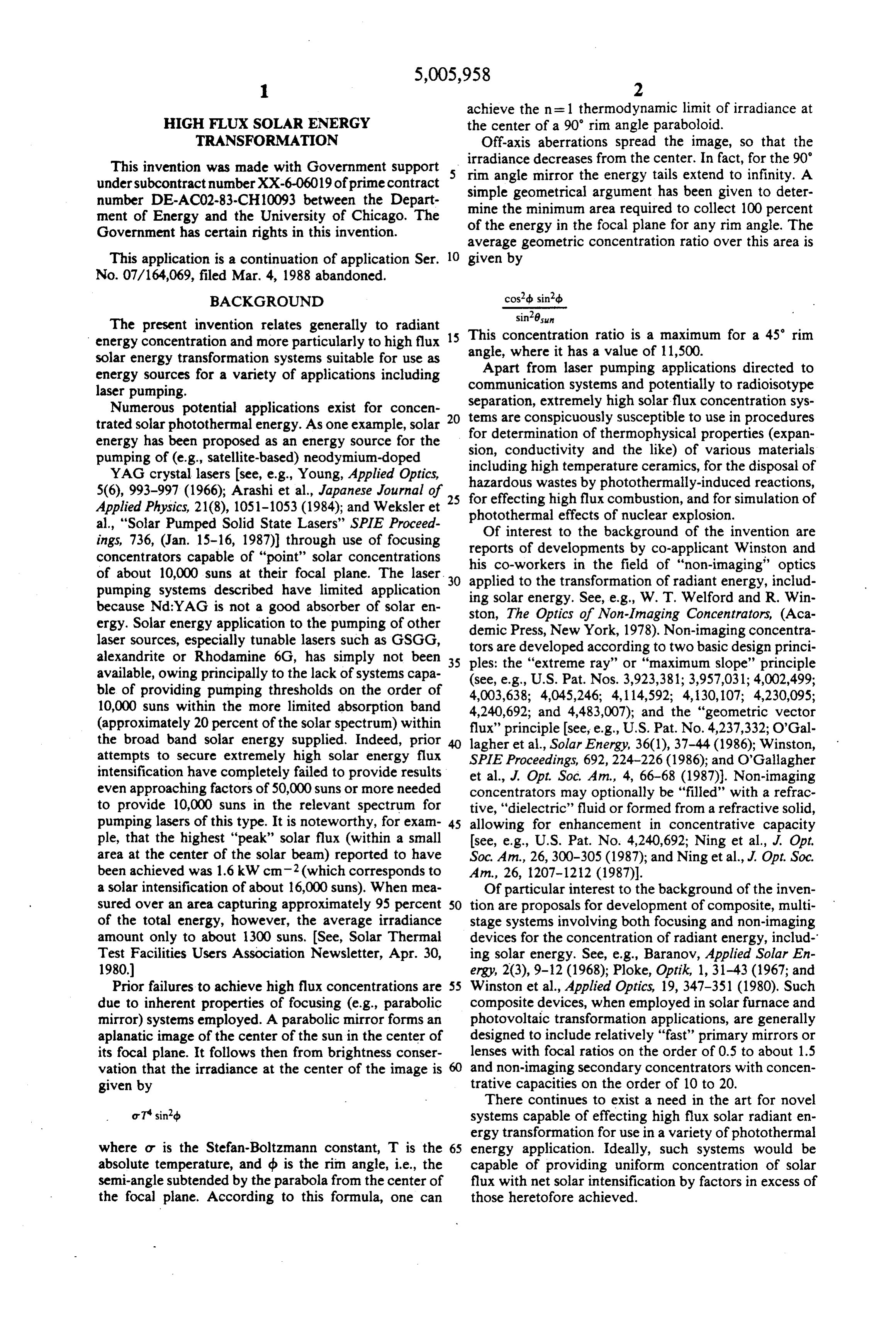
a solar intensification of about 16,000 suns). When mea Of particular interest to the background of the inven sured over an area capturing approximately 95 percent 50 tion are proposals for development of composite, multi of the total energy, however, the average irradiance stage systems involving both focusing and non-imaging amount only to about 1300 suns. See, Solar Thermal devices for the concentration of radiant energy, includ Test Facilities Users Association Newsletter, Apr. 30, ing solar energy. See, e.g., Baranov, Applied Solar En 1980) ergy, 203), 9-12 (1968); Ploke, Optik, 1, 31-43 (1967; and Prior failures to achieve high flux concentrations are 55 Winston et al., Applied Optics, 19, 347-351 (1980). Such due to inherent properties of focusing (e.g., parabolic composite devices, when employed in solar furnace and mirror) systems employed. A parabolic mirror forms an photovoltaic transformation applications, are generally aplanatic image of the center of the sun in the center of designed to include relatively "fast' primary mirrors or its focal plane. It follows then from brightness conser lenses with focal ratios on the order of 0.5 to about 1.5 vation that the irradiance at the center of the image is 60 and non-imaging secondary concentrators with concen given by trative capacities on the order of 10 to 20. There continues to exist a need in the art for novel or Tsin2b systems capable of effecting high flux solar radiant en ergy transformation for use in a variety of photothermal where or is the Stefan-Boltzmann constant, T is the 65 energy application. Ideally, such systems would be absolute temperature, and db is the rim angle, i.e., the capable of providing uniform concentration of solar semi-angle subtended by the parabola from the center of flux with net solar intensification by factors in excess of the focal plane. According to this formula, one can those heretofore achieved.
Page 10
BRIEF SUMMARY
components according to the invention is believed to be clearly illustrated by the following examples wherein
According to the present invention, multistage solar Example 1 relates to the construction of a two-stage radiant energy transformation systems are provided device and Example 2 relates to the use of the device to which allow for solar energy intensification by factors secure uniform irradiance over the entirety of the exit well in excess of any heretofore achievable. aperture of the secondary concentrator which is nearly In brief, systems of the invention are seen to comprise four times the highest irradiation previously reported to a primary solar energy focusing device (preferably a have been achieved over an extremely limited area and mirror or lens) associated with a secondary, non-imag well in excess of 20 times the irradiation reported to ing energy-concentrator (preferably shaped according 10 have been achieved over an area intercepting 95 percent to extreme ray or geometric vector flux principles). The of the solar energy.
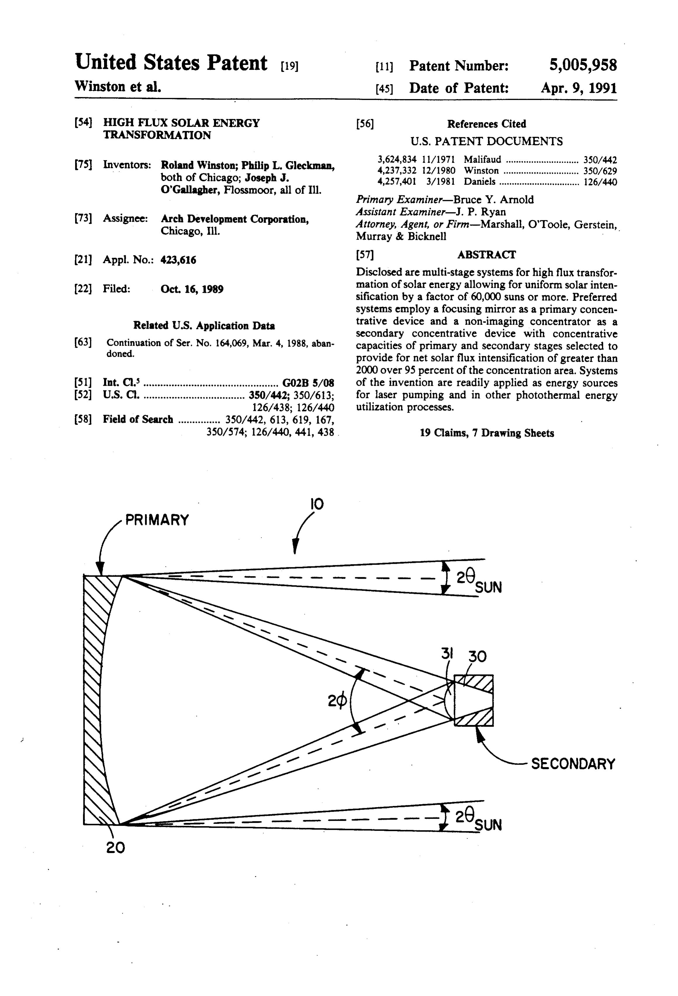
secondary stage is disposed at or near the focus of the primary stage device to receive solar energy therefrom EXAMPLE 1. and the concentrative capacities of primary and second Construction of a multi-stage apparatus according to ary stages are selected and coordinated to allow for a 15 the invention is illustrated in FIG. 1, wherein the system minimum solar intensification of at least 2000 suns, uni 10 is seen to include, as a primary stage a focusing mir formly distributed at the second stage energy exit aper ror and as a secondary stage a non-imaging concentra ture (i.e., distributed over an area intercepting 95 per tor 30.
cent of the concentrated energy). Preferred systems In the embodiment constructed, the primary stage readily achieve unifornly distributed concentrations of mirror was a 40.6 cm parabolic telescope mirror, with a 10,000 suns or more, and those systems including a thickness to diameter ratio of 1:6. The mirror is de secondary concentrator which comprise a high refrac signed to have a rim angle of 11.5 degrees, generating a tive index solid or fluid refracting medium are capable focal ratio of 2.5 and a theoretical maximum concentra-- of providing intensification of greater than the 46,000 tive capacity at its 0.98 diameter image of 730. The sun theoretical maximum concentration in air. Typi mirror was held on an equatorial mount (not shown) cally, the primary stage has a focal ratio of greater than which 2.0 and the secondary stage is designed to concentrate Novak continuously
tracks the sun, and supported on a flotation mirror cell. Also attached to by a factor of about 50 or more. Refractive medium the mount was an Eppley normal incidence pyrheliome filled systems include solid or fluid media which prefer ter (NIP) which continuously measured ably having a refractive index in excess of about 1.3. radiation. Focusing of the solar image on thesolar
secondary
Solid refractive non-imaging second stage concentra stage was done visually under attenuated light by ad tors may be provided which are totally internally reflec justing a microscope focusing mechanism. The highest tive.
A presently preferred prototypical embodiment of irradiance was achieved with a chemical silver coating the systems of the invention comprises a primary focus 35 on the primary. Because it would have reduced the ing mirror device having a focal ratio of about 2.5. broadband reflectivity, no protective dielectric over Disposed at the focus of the primary mirror is a second coat was used on the silver. Protection was provided ary non-imaging device filled with a refractive oil (hav instead by keeping the mirror in a nitrogen enriched environment.
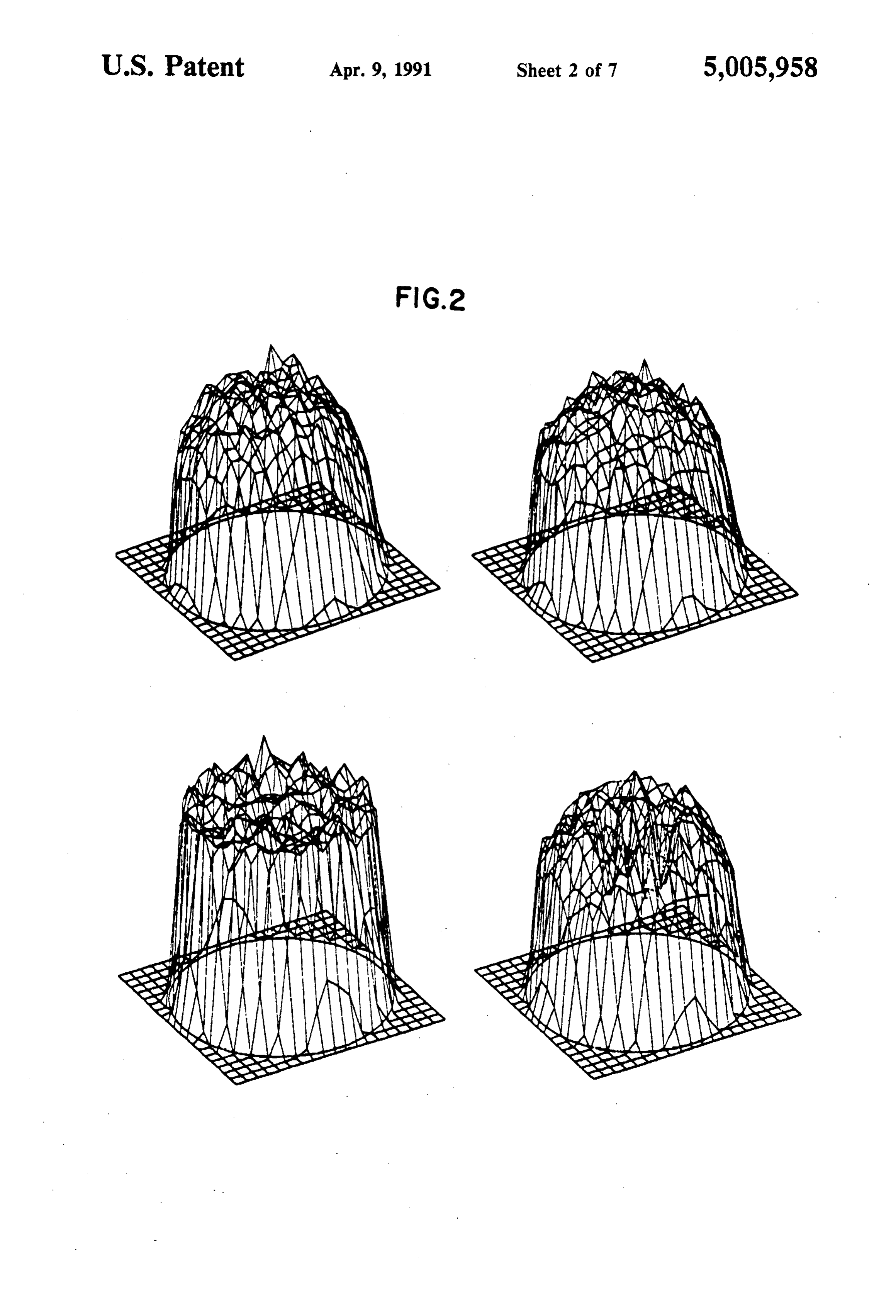
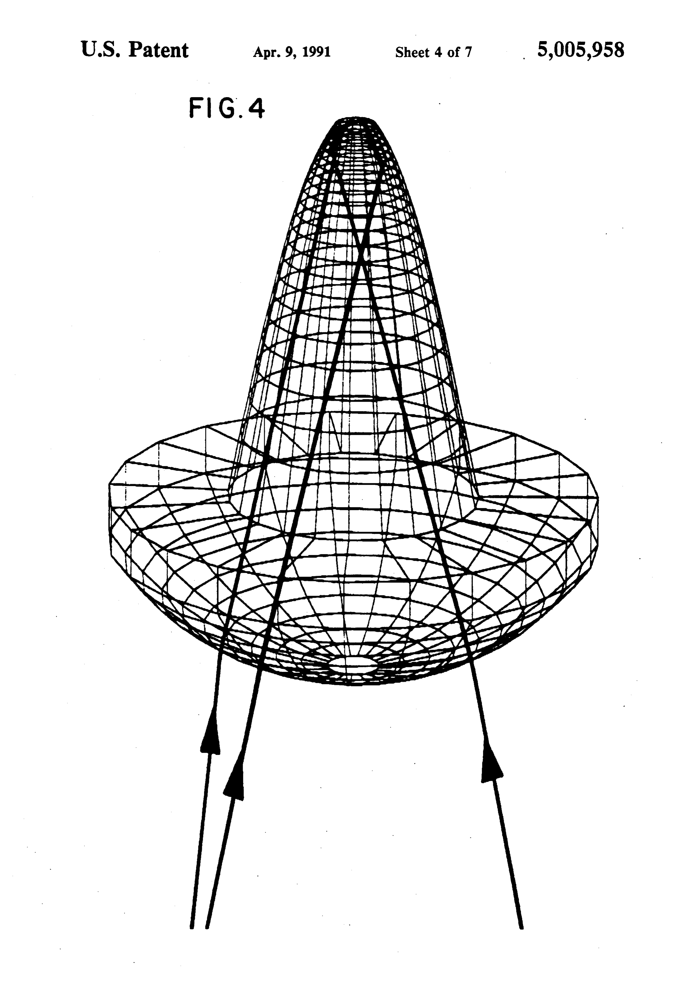
ing a refractive index of about 1.53) and designed for a concentration by a factor of about 60. As verified by Non-imaging concentrator 30 is disposed at the focal calorimeter, this illustrative system allows for solar plane of mirror 10. For use in this prototype, the sec intensification of approximately 60,000 suns and a corre ondary concentrator was designed according to the sponding irradiance of about 5 kW cm2. Systems of extreme ray non-imaging concentrator principle as the invention are readily applied as energy sources for illustrated, for example, in Winston, SPIE Proceedings, laser pumping and in other photothermal energy utiliza 45 692, 224-226 (1986) whereby one images the edge of tion processes. the source at the edge of the exit aperture as illustrated Further aspects and advantages of the invention will in FIG. 3. The concentrator thus included a hollow be apparent upon consideration of the following de vessel 31 fabricated from 99.9 percent pure silver which tailed description of an illustrative embodiment thereof, had been melted and hydraulically pressed onto a con reference being made to the drawing wherein: 50 vex mandrel machined to a tolerance of a few thou FIG. 1 is a schematic representation of a two-stage sandths of an inch. The resulting vessel was 1.2 cm long, system according to the invention; had an entrance aperture of 0.98 cm, an exit aperture of FIG. 2 graphically represents irradiance distributions 1.27 mm and an acceptance angle of 11.5, resulting in a derived from a Monte Carlo raytrace program for pri theoretical maximum concentration (air-filled) capacity mary and secondary stages of a device according to the 55 of 59.7.
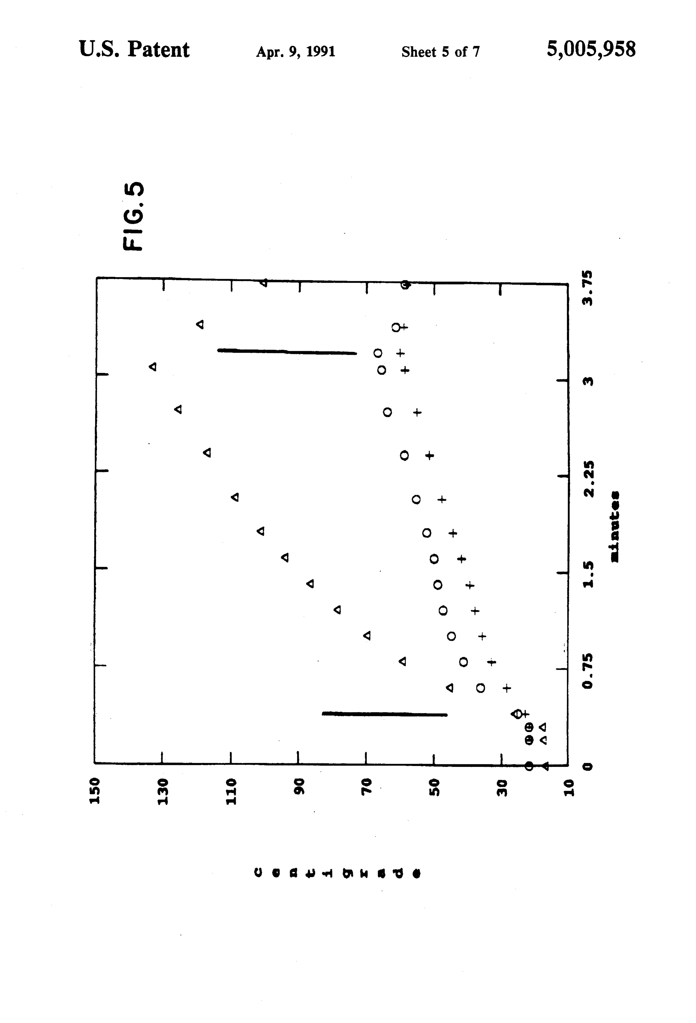
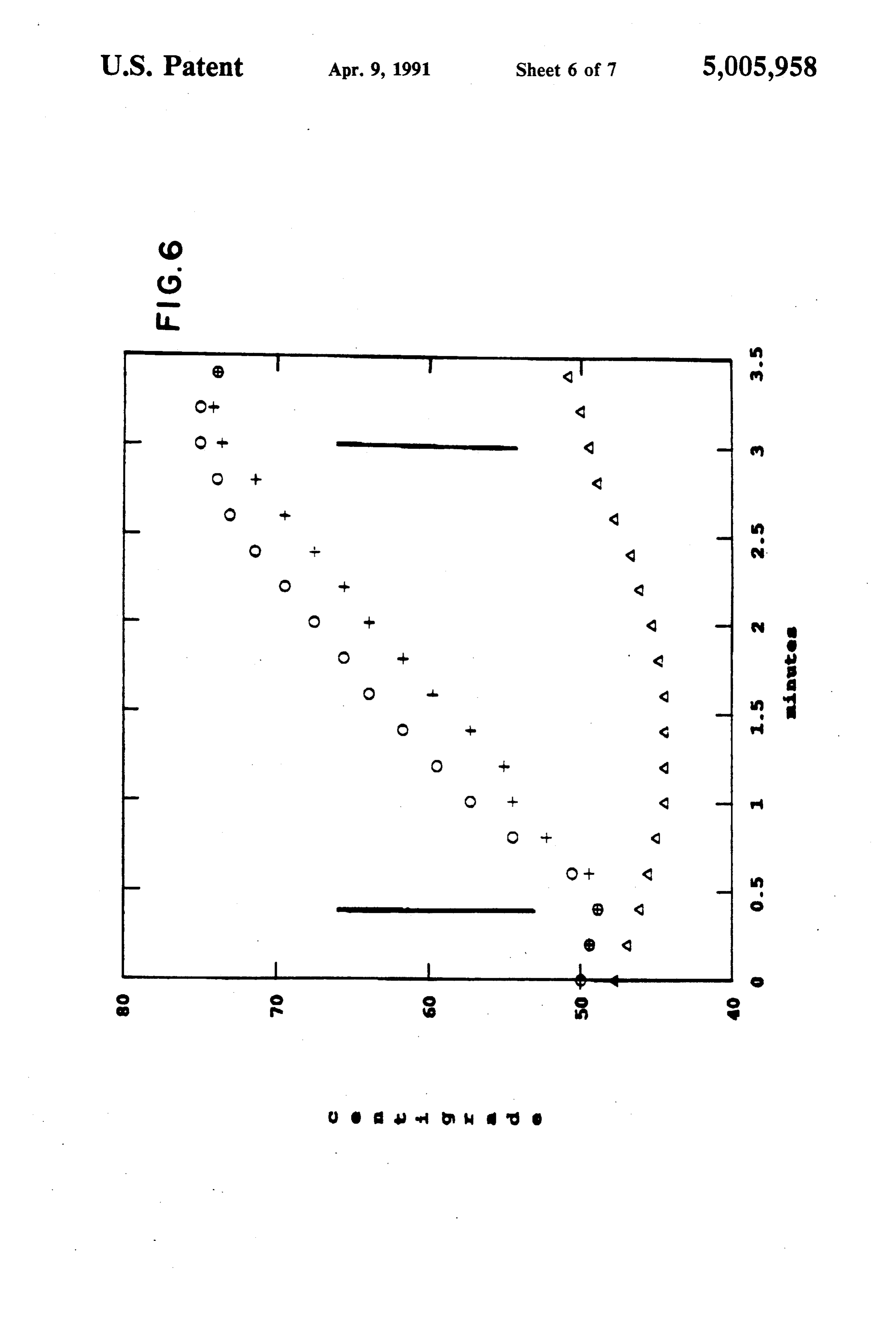
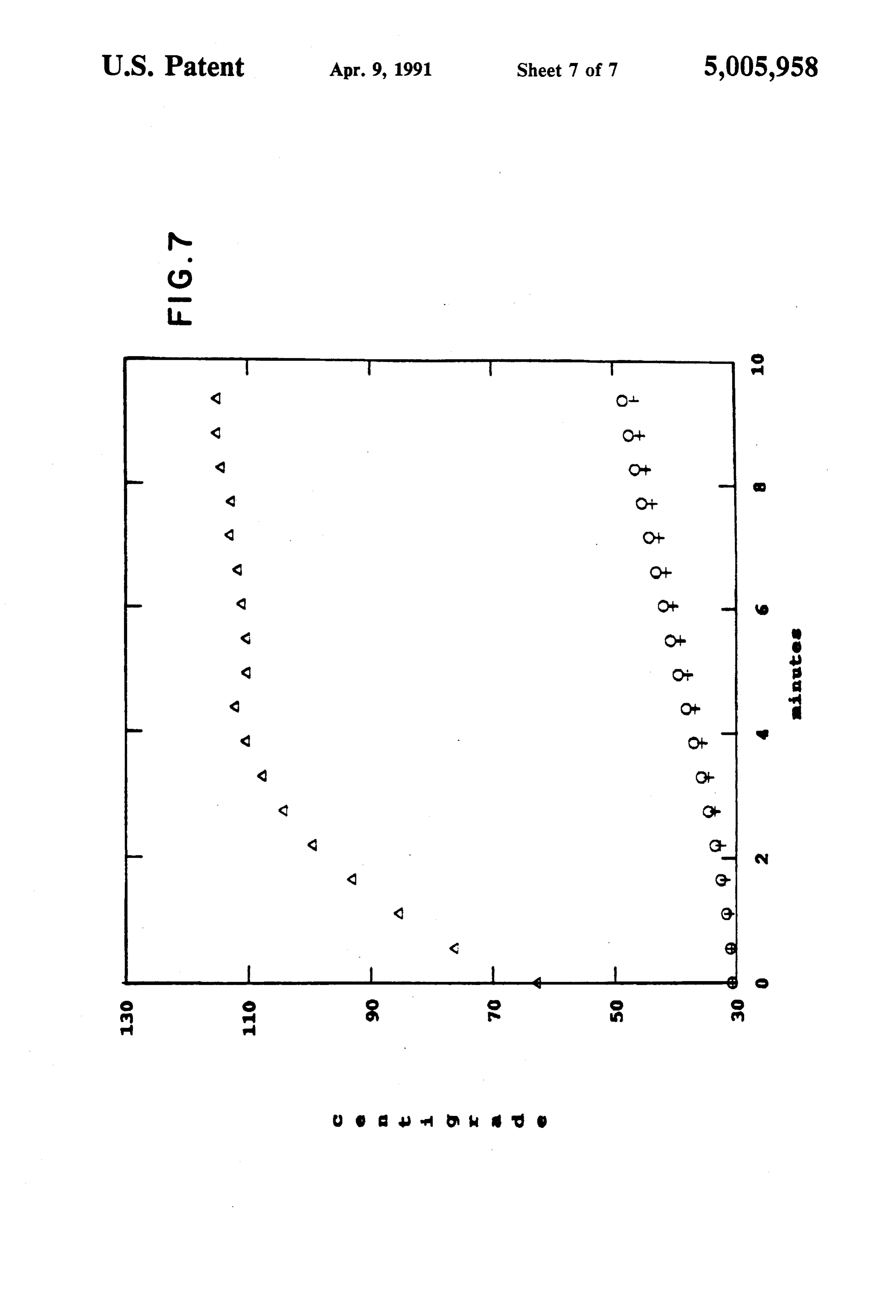
invention; The vessel was then filled with immersion oil (1160, FIGS. 3 and 4 illustrate operation of a second stage R.P. Cargille Laboratories, Cedar Grove, N.J.) which device in practice of the invention; and was selected for its high index of refraction and trans FIGS. 5, 6 and 7 illustrate results of procedures to missivity over the solar spectrum. The index of refrac determine exit irradiance in practice of the invention. tion was measured using a hollow prism spectrograph at
DETAILED DESCRIPTION
various visible wavelengths of mercury. The infrared index was extrapolated using the Cauchy equation and
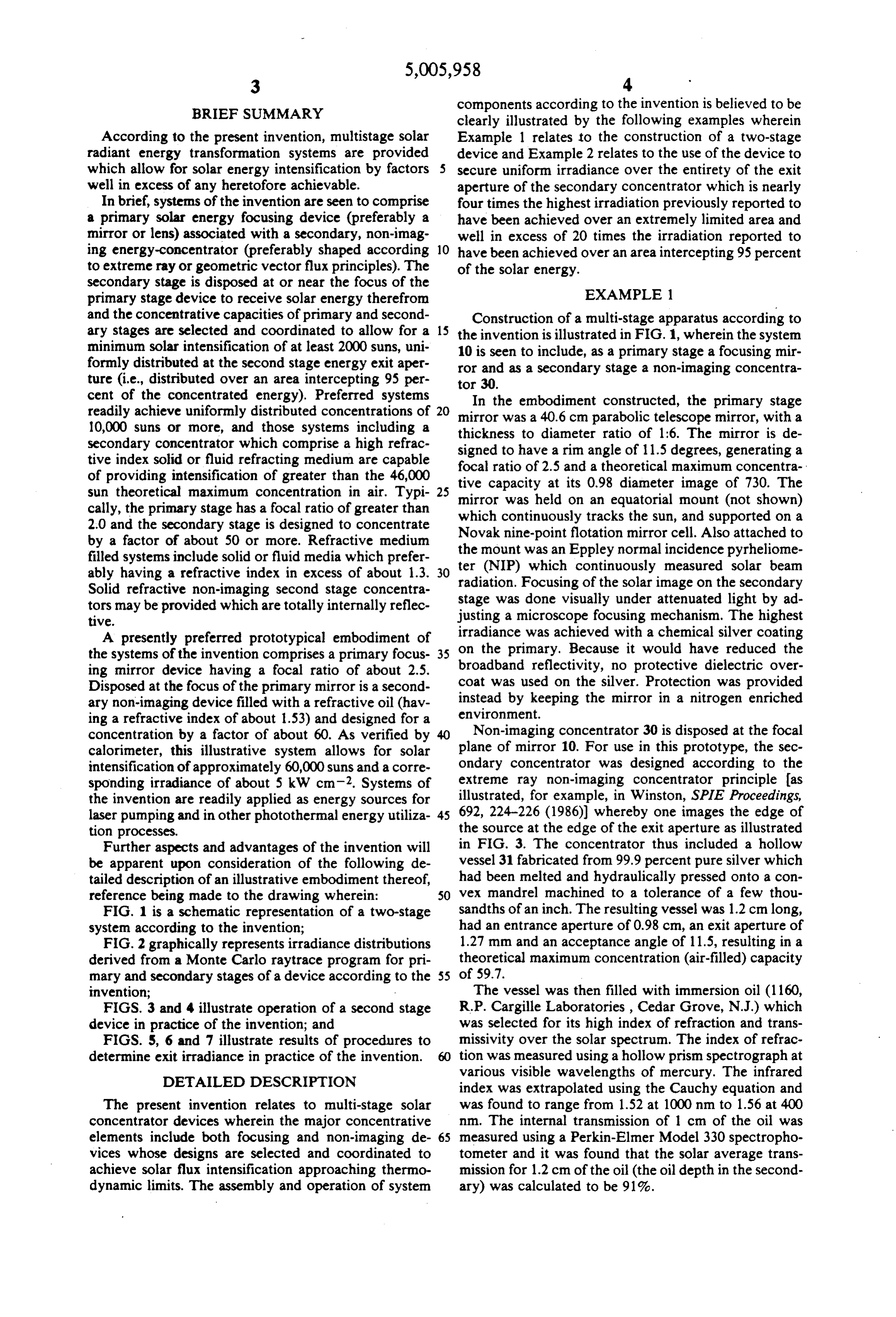
The present invention relates to multi-stage solar was found to range from 1.52 at 1000 nm to 1.56 at 400 concentrator devices wherein the major concentrative nm. The internal transmission of 1 cm of the oil was elements include both focusing and non-imaging de 65 measured using a Perkin-Elmer Model 330 spectropho vices whose designs are selected and coordinated to tometer and it was found that the solar average trans achieve solar flux intensification approaching thermo mission for 1.2 cm of the oil (the oil depth in the second dynamic limits. The assembly and operation of system ary) was calculated to be 91%.
Page 11
The vessel was capped by a plano-convex lens 31 two factors: the average brightness is nearly equal to the (Schott BK-7) which has an index of 1.51 in the visible. thermodynamic limit, and the local brightness must not See FIG. 4. The secondary stage was assembled in the exceed the limit:
following sequence. First, the lens was mounted in be The following example relates to projection and ac tween the empty vessel and a flange which has an aper tual measurement of the efficiency in solar flux concen ture the size of the solar image. Next, the oil was in tration of the prototype multi-stage system of Example jected with a syringe through the exit aperture. Finally, 1.
the complete secondary is kept under vacuum until bubbles and dissolved gases are removed. EXAMPLE 2 In order to reduce the amount of heating in the sec 10 Deviations from ideal performance resulting from the ondary, a filter was constructed to remove light that would be absorbed by the oil in the secondary. The optical the materials and design employed in assembly of system of Example 1 were calculated as follows in ideal filter for this job consists of two thin anti-reflec order to ascertain tion coated glass windows surrounding an optimized energy incidence andthegeometriclikely variance of actual solar projection. Among the thickness of the same oil used in the secondary. A 1 cm 15 primary stage losses were an approximately 3% loss due thickness was chosen on the basis of a tradeoff between lowering absorption in the secondary and maintaining a to reflection inefficiency of the primary mirror and an high throughput. The overall effect of the filter was to approximately 15% loss due to extensive, mirror shad halve the absorption in the secondary while reducing ing as a result of extensive, substantially oversized sup the net transmission by only 3.7%. port elements employed to support the secondary con By placing a nonimaging secondary device 30 in the centrator calorimeter measuring device between the focal plane of the parabolic mirror 20, an irradiance at mirror and the solar source. The net primary receiver the thermodynamic limit can be produced uniformly efficiency was 82.4%. Projected design and material over the entire exit aperture. Furthermore, because the losses in the secondary stage totalled 24.2% based on an secondary stage is filled with a material with index of 25 estimated 1.5% loss due to lens reflection, a 2.9% loss refraction (n) greater than one, the thermodynamic due to skew rays (the secondary stage being designed in limit is increased by a factor of n. In a two-stage sys the meridional plane), a 12.7% loss due to energy ab tem, the secondary stage entrance aperture is made to sorption of the immersion oil, a 7% loss due to intraves coincide with the solar image, and the acceptance angle sel reflections and a 2.4% loss due to lens oversizing of the secondary is made to coincide with the rim angle needed to insure retention of the refractive fluid. The of the primary and the etendue is conserved. The index 30 net projected 75.8% efficiency of the secondary stage, of refraction and the acceptance angle of the secondary when considered with the 82.4% net primary stage determine its concentration, according to the theoreti efficiency result in a projected overall efficiency of cal limit: 62.4% of the geometric limit with a resultant projected
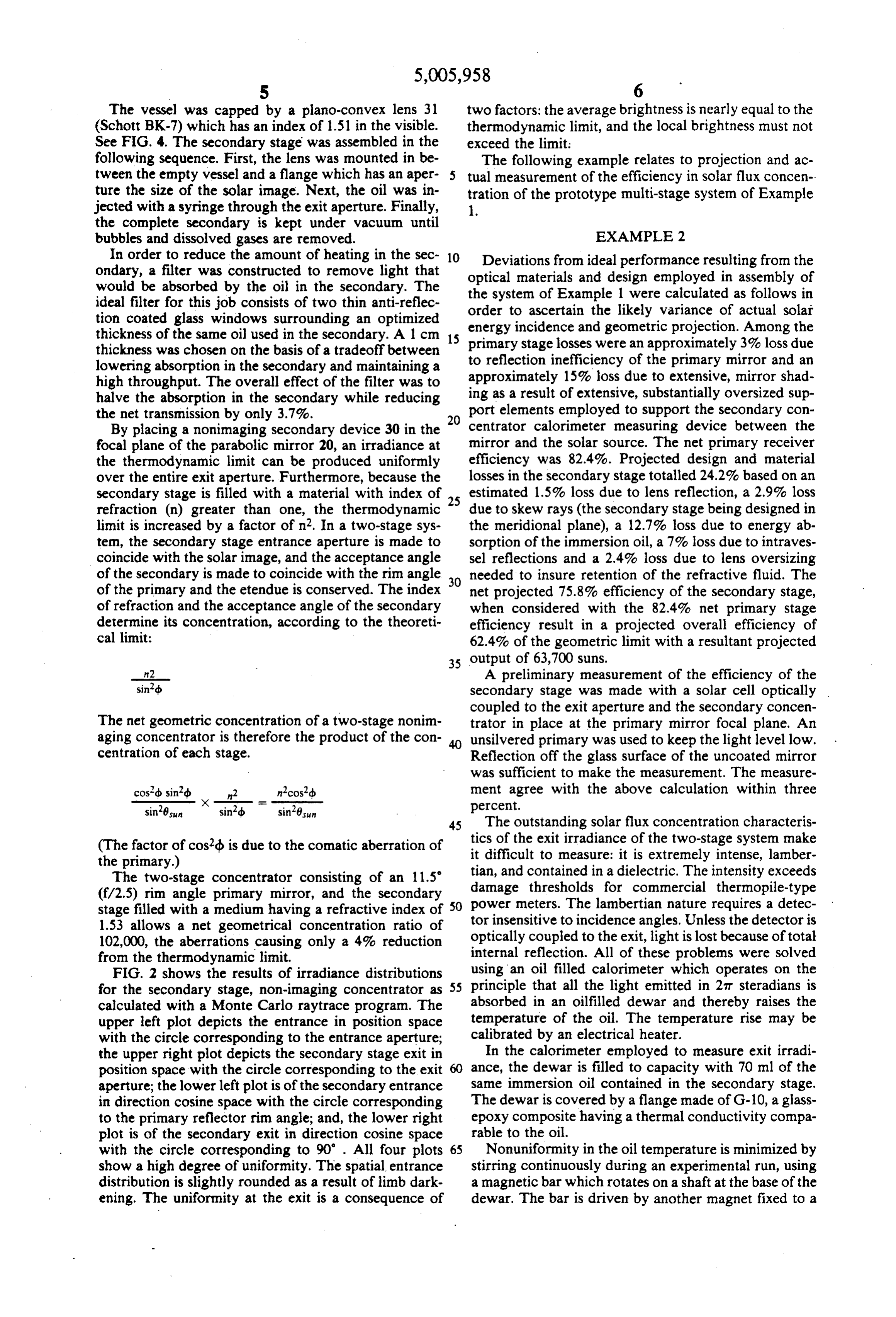
n2 A preliminary measurement of the efficiency of the sind secondary stage was made with a solar cell optically coupled to the exit aperture and the secondary concen
The net geometric concentration of a two-stage nonim trator in place at the primary mirror focal plane. An aging concentrator is therefore the product of the con unsilvered primary was used to keep the light level low. centration of each stage. Reflection off the glass surface of the uncoated mirror was sufficient to make the measurement. The measure cosd sind n2 nicos?db ment agree with the above calculation within three sin'8sun x -sind = -sin’8sun percent.
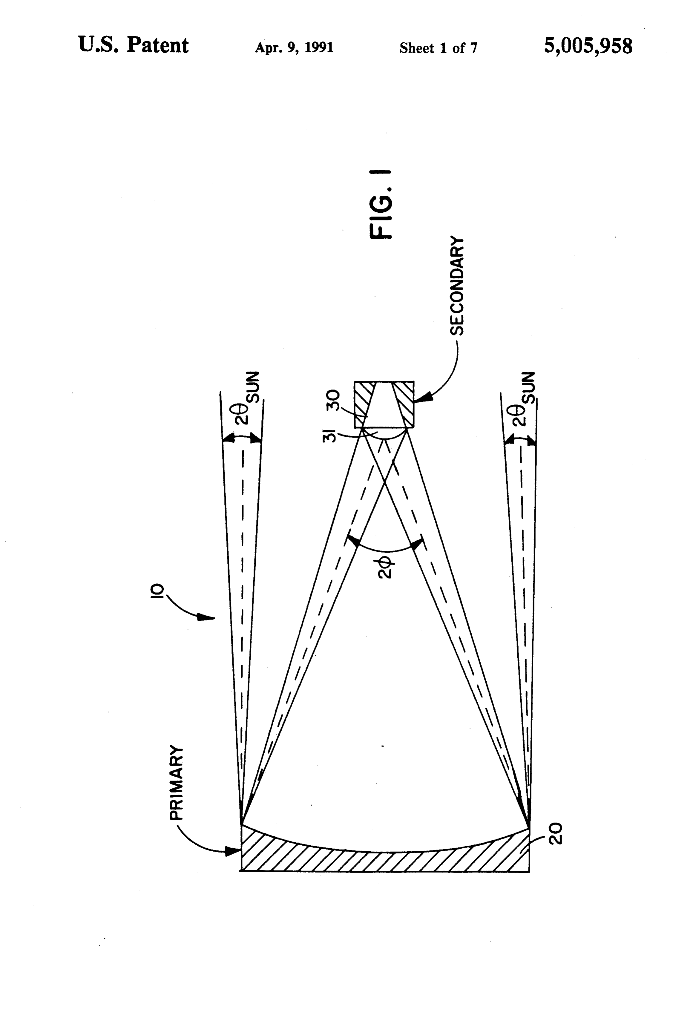
45 The outstanding solar flux concentration characteris
(The factor of cosd is due to the comatic aberration of tics of the exit irradiance of the two-stage system make the primary.) it difficult to measure: it is extremely intense, lamber The two-stage concentrator consisting of an 11.5 tian, and contained in a dielectric. The intensity exceeds (f/2.5) rim angle primary mirror, and the secondary damage thresholds for commercial thermopile-type stage filled with a medium having a refractive index of 50 power meters. The lambertian nature requires a detec 1.53 allows a net geometrical concentration ratio of tor insensitive to incidence angles. Unless the detector is optically coupled to the exit, light is lost because of total 102,000, the aberrations causing only a 4% reduction internal from the thermodynamic limit. reflection. All of these problems were solved FIG. 2 shows the results of irradiance distributions using an oil filled calorimeter which operates on the for the secondary stage, non-imaging concentrator as 55 principle that all the light emitted in 27T steradians is calculated with a Monte Carlo raytrace program. The absorbed in an oilfilled dewar and thereby raises the upper left plot depicts the entrance in position space temperature of the oil. The temperature rise may be with the circle corresponding to the entrance aperture; calibrated by an electrical heater. the upper right plot depicts the secondary stage exit in In the calorimeter employed to measure exit irradi position space with the circle corresponding to the exit ance, the dewar is filled to capacity with 70 ml of the aperture; the lower left plot is of the secondary entrance same immersion oil contained in the secondary stage. in direction cosine space with the circle corresponding The dewar is covered by a flange made of G-10, a glass to the primary reflector rim angle; and, the lower right epoxy composite having a thermal conductivity compa plot is of the secondary exit in direction cosine space rable to the oil.
with the circle corresponding to 90' . All four plots 65 Nonuniformity in the oil temperature is minimized by show a high degree of uniformity. The spatial entrance stirring continuously during an experimental run, using distribution is slightly rounded as a result of limb dark a magnetic bar which rotates on a shaft at the base of the ening. The unifornity at the exit is a consequence of dewar. The bar is driven by another magnet fixed to a
Page 12
notor outside the dewar. The heating caused by the same as during the solar heating experiment: the dewar stirring process is negligible. was upside-down, and the oil was stirred. The warm-up The heater employed for calibration was composed curves are shown in FIG. 7. The temperature rises were of Teflon sewn with nichrone wire, and had a resis calibrated by the electrical heater.
tance of 9 ohms. The DC electrical power was deter A value for h of 947-100 m2 C-1 was obtained. mined from the product of the measured current and Therefore, Qu is 4.1 W and Qelis 1.3 W. With this (7%) measured four-wire voltage.
Two light-shielded nichrome-constantan thermocou correction, a value of Port of 61.4 W is determined. ples were at different, shallow and deep positions in the ance of about by
Dividing Pop the exit aperture area gives an irradi
oil. Without shielding, the thermocouples warm up 10 The irradiance ratio is defined as the ratio of the very quickly from direct optical absorption. A third thermocouple is inserted tightly into the body of the irradiance rect exiting the concentrator to the incident di irradiance as measured using a normal incidence cast silver secondary concentrator vessel. pyranometer (NIP). The NIP measures all of the inci A high irradiance testing procedure was performed dent irradiance contained within its 2.75 acceptance by first measuring the temperature rise of the oil when 15 angle and because the sun subtends the primary is illuminated. Typical warm-up curves are measurement includes circumsolar only 0.27", the NIP radiation. The cir shown in FIG. 5. This Figure plots temperature versus cumsolar to beam (circumsolar plus direct) ratio was time during solar heating with triangles, circles and measured using a solar cell. The cell was placed in the crosses respectively indicating the concentrator vessel primary and shallow and deep thermocouple readings, and verti 20 the size offocal plane. A mask with an aperture equal to cal bars indicating the opening and closing of the pri light was attenuatedimage the solar was mounted on the cell. The with aluminum coated glass. The mary mirror to sunlight. The average rate of tempera short circuit current was measured with an without the ture rise, ATsun/Alt was taken from the temperature at mask. The resulting circumsolar the starting point (primary open) and at the isothermal 10%. The ratio of the exit irradiance ratio was found to be ending point (primary closed). Readings from the two 25 to the direct insola thermocouples in the oil were averaged. The final tem tion was thus determined to be on the order of perature was chosen low enough so that the oil refrac 60,000-5,000 suns.
tive index and vessel reflectivity are not significantly Numerous modification and variations in practice of reduced. The boiling point of the oil is 370 C. at one the the invention are expected to occur to those skilled in atmosphere pressure. The average rate of temperature 30 art upon consideration of the above illustrative ex rise for this run was 0.2428 C./sec., and the average amples. As previously indicated, systems of the inven beam insolation was 888 Wm2. tion are susceptible to application in the provision of Right after the oil has cooled, the temperature rise energy for pumping lasers. The laser design contem due to electrical heating was measured with the primary plated for a solid state laser rod has one end of the rod mirror completely blocked. The heater warmup curves 35 optically coupled to the secondary exit aperture. This are shown in FIG. 6. The average rate of temperature end is coated with a dielectric mirror which is transpar rise ATel/At was determined from the isothermal points ent to the pump light but reflective at the emission at which the heater was turned on and off (vertical wavelength. The other end of the rod is either uncoated bars). The average rate of temperature rise was 0.161" for an external output mirror or coated with a partially C./sec. The electrical power, Pel, was 51 Watts. transparent dielectric mirror. The rod sides are un In the case of the solar heating, the secondary vessel coated and the rod maintains high pump concentration temperature was higher than that of the oil. This means using total internal reflection. Preliminary estimates of that an amount of heat Qun is transferred by convection substantial comparative efficiencies of solar pumped from the secondary to the oil. The reverse occurs when dye lasers in keeping with the invention (compared, for the electrical heater is turned on; the oil gives up an 45 example, to argon ion pumped lasers) take into account amount of heat Qel to the secondary. The convective the fact that the overall efficiency of the system is essen heat transfer, though small, must be included to deter tially limited only by the efficiency of the dye laser mine the true optical power, Pop. Once Qsun and Qel are component itself in solar pumped devices. determined, the optical power is calculated by It will be apparent to those skilled in the art that 50 delivery of solar energy to the primary mirror or lens
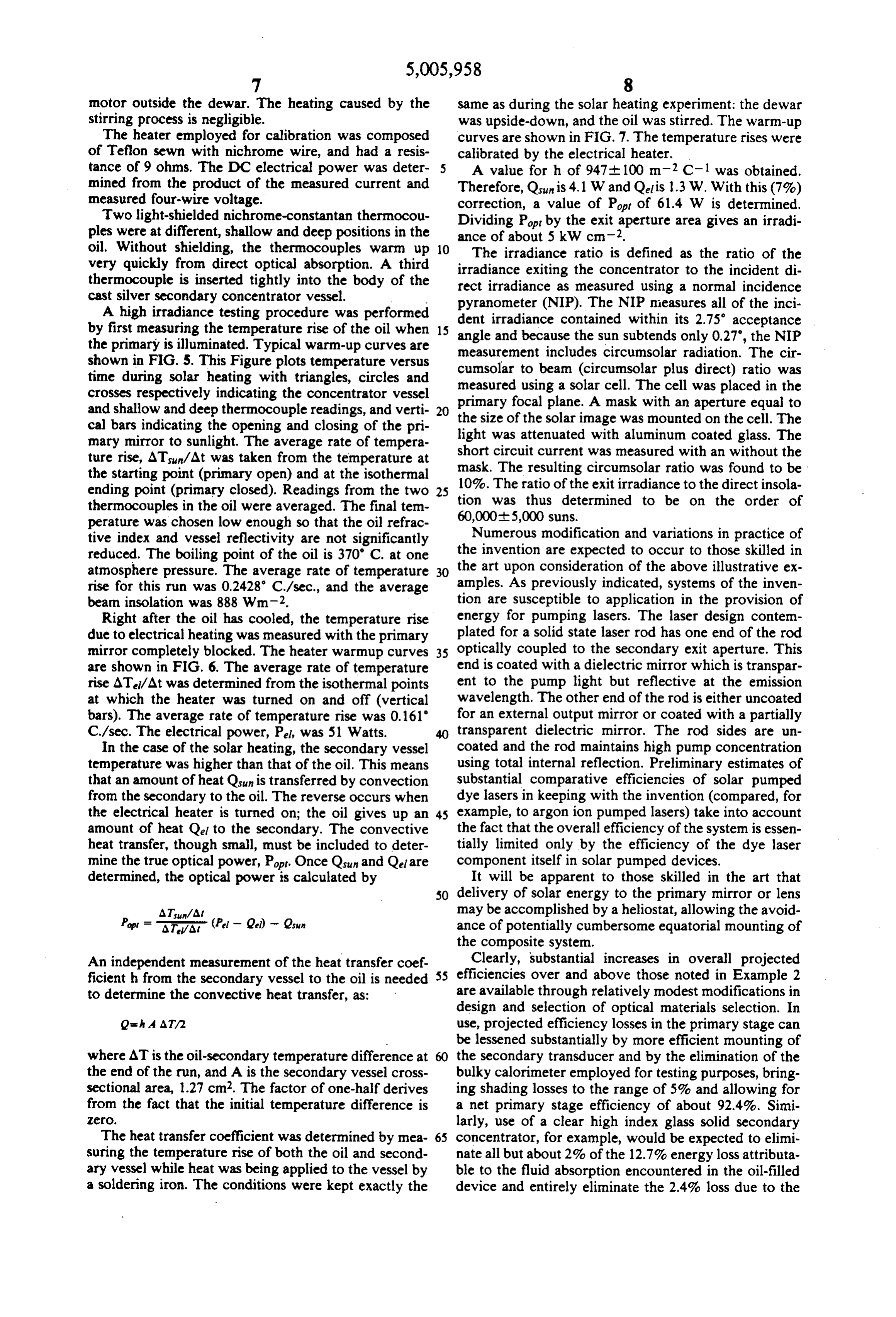
ATsun/At may be accomplished by a heliostat, allowing the avoid Pop F AA- (P - Q) - Qun ance of potentially cumbersome equatorial mounting of the composite system.
Clearly, substantial increases in overall projected
An independent measurement of the heat transfer coef 55 efficiencies ficienth from the secondary vessel to the oil is needed over and above those noted in Example 2 to determine the convective heat transfer, as: are available through relatively modest modifications in design and selection of optical materials selection. In
Q= A AT/2 use, projected efficiency losses in the primary stage can be lessened substantially by more efficient mounting of where AT is the oil-secondary temperature difference at the secondary transducer and by the elimination of the the end of the run, and A is the secondary vessel cross bulky calorimeter employed for testing purposes, bring sectional area, 1.27 cm2. The factor of one-half derives ing shading losses to the range of 5% and allowing for from the fact that the initial temperature difference is a net primary stage efficiency of about 92.4%. Simi O. larly, use of a clear high index glass solid secondary The heat transfer coefficient was determined by mea 65 concentrator, for example, would be expected to elimi suring the temperature rise of both the oil and second nate all but about 2% of the 12.7% energy loss attributa ary vessel while heat was being applied to the vessel by ble to the fluid absorption encountered in the oil-filled a soldering iron. The conditions were kept exactly the device and entirely eliminate the 2.4% loss due to the
Page 13
lens oversizing (required to safely "contain' the oil). 6. The system according to claim 5 wherein said Skew ray losses may also be eliminated by flow line primary stage device has a focal ratio of 2.5 or more. designs and intravessel reflections would be made negli 7. The system according to claim 1 wherein said gible through use of a totally internally reflective sec secondary stage non-imaging means for concentrative ondary concentrator. Net secondary stage efficiencies transmission of solar energy has a concentrative capac on the order of about 94% could thus be projected and ity8.ofThe greater than 50.
the combined effect of both primary and secondary secondary system according to claim 1 wherein said efficiencies could thus provide for a net system effi transmissionstage non-imaging means for concentrative of solar energy comprises a non-imaging ciency on the order of 85% rather than 62.4% achieved 10 transducer shaped according to the extreme ray design by the prototype. principle.
Only such limitations as appear in the appended 9. The system according to claim 8 wherein said claims should restrict the scope of the present invention. transducer shape is non-parabolic. What is claimed is: 10. The system according to claim 1 wherein said 1. A multi-stage solar radiant energy transformation 15 secondary stage non-imaging means for concentrative system, said system comprising: transmission of solar energy comprises a non-imaging (a) as a primary stage, a means for focusing solar transducer shaped according to the geometric vector energy; flux principle.
(b) as a secondary stage, a non-imaging means for 20 11. The system according to claim 1 wherein said concentrative transmission of solar energy to an secondarytransmission stage non-imaging means for concentrative of solar energy comprises a refractive me energy exit aperture, said secondary stage disposed in energy receiving dium having an index of refraction greater than 1.0 12. The system according to claim 11 wherein the relation to said primary stage solar energy focus refractive index of said medium is 1.4. or more. ing means, and the concentrative capacities of 25 13. The system according to claim 11 wherein said said primary and secondary stages selected to refractive medium is a solid.
provide a net solar flux intensification of at least 14. The system according to claim 13 wherein the 2000 uniformly distributed at the secondary solid refractive medium is clear high index glass. stage energy exit aperture. 15. The system according to claim 13 wherein said 2. The system according to claim 1 wherein the con 30 solid refractive medium is totally internally reflective. centrative capacities of said primary and secondary 16. The system according to claim 11 wherein said edges provide a net solar flux intensification of greater refractive medium is a liquid.
than 46,000 uniformly distributed at the secondary stage fluid 17. The system according to claim 16 wherein said energy exit aperture. refractive medium is an oil. 35. 18. A system according to claim 1 wherein said sec 3. The system according to claim 1 wherein said ondary stage means for concentrative transmission of primary stage comprises a focusing mirror device.
4. The system according to claim 1 wherein said solar energy provides a solar energy exit angle of less
primary stage comprises a focusing lens device. 19. A system according to claim 1 further comprising 5. The system according to claim 3 or 4 wherein said heliostat means for directing solar energy to said pri primary stage device has a focal ratio of greater than mary stage.
2.0. sk sk k
Provenance
- Collection
- Cited prior art
- Original PDF
- patentimages.storage.googleapis.com →
- Filed
- 1989-10-16
- Pages
- 13
- Method
- pdftotext (the PDF's own text layer) + pdftoppm 300dpi page scans
- Source
- Google Patents bibliographic record
- Granted
- 1991-04-09
- Inventors
- Roland Winston; Philip L. Gleckman; Joseph J. O'Gallagher; Arch Development Corp
- Transcribed from
- patentimages.storage.googleapis.com →