patent · US5587057
Highly conductive liquid media electrocoagulation
24 December 1996
Page 1 — bibliographic record
United States Patent (19) 11 Patent Number: 5,587,057 Metzler et al. 45 Date of Patent: Dec. 24, 1996 54 HIGHLY CONDUCTIVE LIQUID MEDIA 4,285,805 8/1981 Stegelman ............................... 208/13 ELECTROCOAGULATION 4,350,590 9/1982 Robinson ...... ... 204/661 4,378,276 3/1983 Liggett et al. . . 204/149 (75) Inventors: David M. A. Metzler, 1001 Winchester, 27. S.y
S. adet al.
OOrecad C
SEGE St Mt
Albert L. 4,872,959 10/1989 Herbst et al. .....
4. 4,917,782 4/1990 Davies ...... ... 205/743 73) Assignec: payid
M. A. Metzler, Kansas City, 4,988,427 1/1991 Wright .................................... 204/661 Primary Examiner-Arun S. Phasge 21 Appl. No.: 163,683 Assistant Examiner William T. Leader Attorney, Agent, or Firm-Litman, McMahon and Brown, 22 Filed: Dec. 7, 1993 L.L.C.
Related U.S. Application Data 57) ABSTRACT
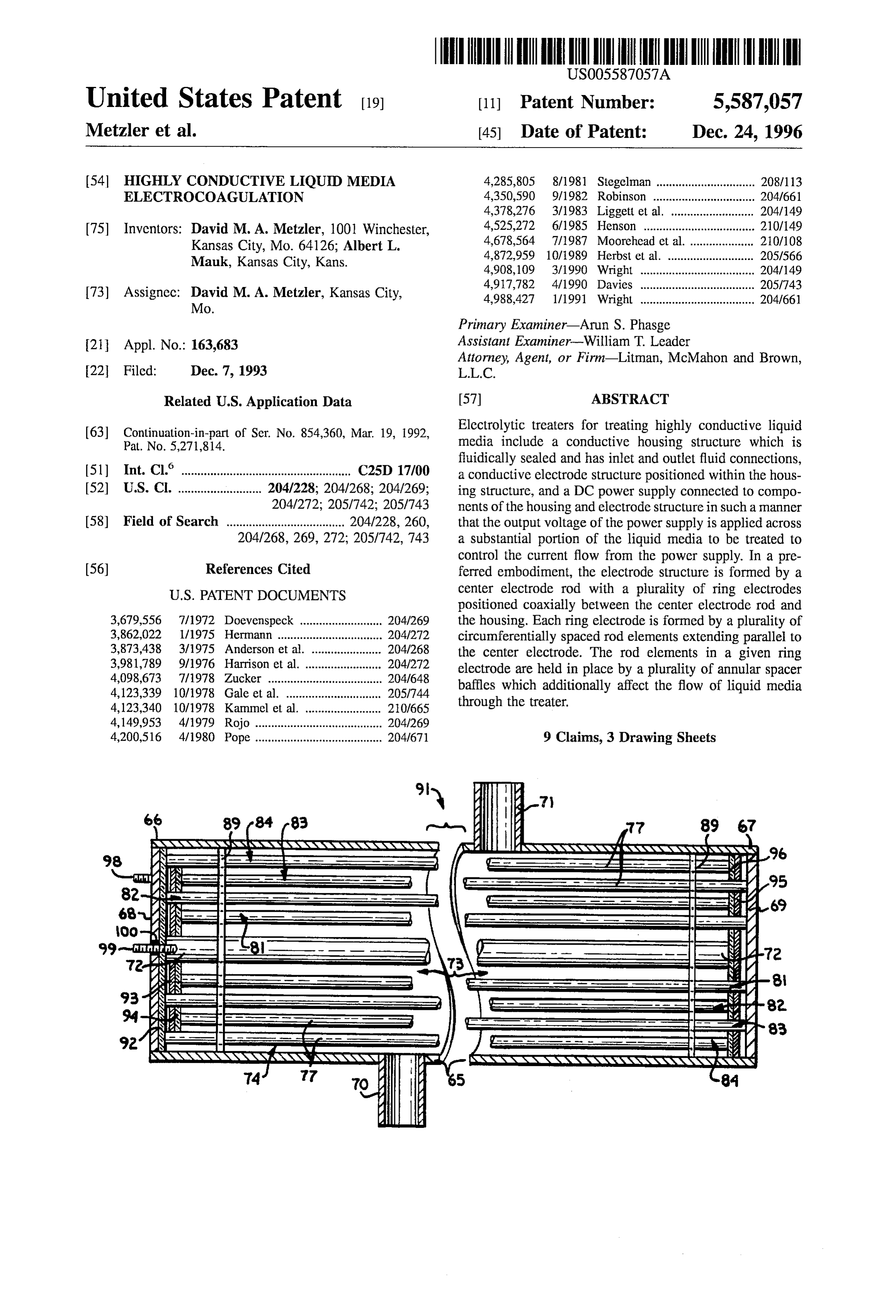
of Ser. No. 854,360, Mar. 19, 1992, Electrolytic treaters for treating highly conductive liquid media include a conductive housing structure which is 6 fluidically sealed and has inlet and outlet fluid connections, (51) Int. Cl. .................................................... C25D 17700 a conductive electrode structure positioned within the hous (52) U.S. Cl. .......................... 204/228; 204/268; 204/269; ing structure, and a DC power supply connected to compo 204/272; 205/742; 205/743 ments of the housing and electrode structure in Such a manner 58) Field of Search ..................................... 204/228, 260, that the output voltage of the power supply is applied across 204/268,269, 272; 205/742, 743 a substantial portion of the liquid media to be treated to control the current flow from the power supply. In a pre (56) References Cited ferred embodiment, the electrode structure is formed by a center electrode rod with a plurality of ring electrodes
3,679,556 7/1972 Doevenspeck ....... ... 204/269 the housing. Each ring electrode is formed by a plurality of 3,862,022 1/1975 Hermann .............. ... 204/272 circumferentially spaced rod elements extending parallel to 3,873,438 3/1975 Anderson et al. ... ... 204/268 the center electrode. The rod elements in a given ring
2,3. electrode are held in place by a plurality of annular spacer 4,123,339 10/1978 Gale et al. ....... ... 2051744 ball aditionally affect the flow of liquid media 4,123,340 10/1978 Kammel et al. . ... 20/665 ough the trealer.
4,149,953 4/1979 Rojo ............. ... 204/269 4,200,516 4/1980 Pope ........................................ 2041671 9 Claims, 3 Drawing Sheets
NASASNNNNNNNNNNYNNNNNNNNNN NZ NNNNNNNNYS NaNNYaYa YaYaNYaYa NaNNNYS 96 98. SEE EEE E. 28S 2. BSE EEE EEE 95
2. 2S Race e2 Oo-KSKN R 'EEE 22NE a/
area DeY
94 2ss EEEEEEE a.
Lee sessess E.
NYNYYYYYYYYYYNNNNNNNYN N KNNNNRS
Page 2
Drawing sheet — no readable text.
Page 3
Drawing sheet — no readable text.
Page 4
Drawing sheet — no readable text.
Page 5
HIGHLY CONDUCTIVE LIQUID MEDIA sludges and other contaminant sludges which added to the ELECTROCOAGULATION cost of disposal. Many current systems for performing electrolytic treatments are batch and dump methods which
CROSS REFERENCE TO RELATED have a high labor cost, since each batch is individually APPLICATIONS sampled, treated, and separated prior to beginning the sec ond batch.
Thc prescnt application is a continuation in part of Ser.
On-line electrolytic systems, as opposed to batch systems,
No. 07/854,360 filed Mar 19, 1992 on THIN FILM ELEC require large spaces for process retention time. Retention
TROCOAGULATION FOR REMOVAL OF CONTAMI
NANTS FROM LIQUID MEDIA, now U.S. Pat. No. 5,271, 10 time is critical for thc on-line system to obtain treatment 814 issucd Dec. 21, 1993. standards. Retention time can be shortened with higher voltage and more electrical power consumption. On-line
BACKGROUND OF THE INVENTION systems usually require a larger electrical supply, due in part to the retention time and the voltage required to electrically
In attempting to control environmental pollution from charge the pipe mass which is delivering the charge and industries, human waste, and naturally decomposing miner 15 transporting the liquid through the system. Capital costs are als and chemicals, a wide variety of chemical and mechani high and the cost for electrical power to operate the system cal processes have been developed. is expensive. Since the required voltage and amperage Chemical methods havc attempted to cause a predeter across the poles is high the resulting flux is such that the mined reaction between chemical additives and impurities 20 piping deteriorates quickly, and maintenance for replacing contained within an aqueous solution. The most common the piping is frequent.
reactions arc designed to cause coalescences of the impuri Other electrolytic devices have solved many of the prob tics and the chemical additives. As the coalescing occurs the lems of size, cost, and electrical power consumption in the materials flocculate and the particles which are then formed prior art. However, none has accomplished the treatment of collect in laycrs, or "layer' according to their specific 25 highly conductive waters such as sea water, acid quench gravity within the aqueous solution. Many times, to effec waters, mineral waters with salts, and neutralized water high tively remove the chemically flocculated contaminants, in sulfates. High concentrations of conductive contaminates additional chemicals are added to increase the size of the have caused short circuiting of previous devices, such that particles and, thus, the specific gravity of the particle. only limited applications of treatments of such solutions Increasing the size of the floc with additional chemical 30 have been accomplished. Those previous treatments were additives causes more rapid settling and better defined accomplished in some cases by dilution of the solutions with segregated layering within the solution. Air can be added to non-conductive materials. However, the resulting low effi some solutions to cause a more rapid rise of the flocculated ciency has caused this practice to be discontinued due to the particles when the formed particles have a lighter specific lack of economic feasibility.
gravity than the base solution. Combinations of chemicals 35 Accordingly, there is a need for an efficient, low cost and air can be uscd for complex aqueous solutions that have system which embodies the best of all previous systems, yet more than one contaminant. allows treatment of highly conductive solutions and remains Mechanical methods are designed to achieve similar flexible to treat a wide variety of other waste streams results as chemical additives, but to a lesser degree of purity on-line, with minimal maintenance and energy cost. in the final aqueous solution. Filters, centrifuges, plate 40
Separators, and clarifiers are the most common mechanical SUMMARY OF THE INVENTION methods employed to remove contaminants from aqueous solutions. In most cases the impurities that are removed The present invention provides configurations of treaters mechanically are suspended solids or dissolved particles that and processes using such treaters which are especially are flocculated by changes in process temperature or reten 45 adapted for electrolytically treating liquid media having high tion time in the processed solution. conductivities. The present invention approaches the prob Over two decades ago, the chemical and mechanical lem of electrolytically treating high conductivity liquids by methods of treating the aqueous solutions were thought to be configuring the treaters so that within the treaters, the liquid adequate treatment prior to disposal. Disposal of the treated medium is divided into portions by sections of the elec aqueous solution into the oceans, streams, lakes, and under 50 trodes. The output voltage of the power supply is applied ground wells were common. Tests have shown that small across multiple portions of the liquid thereby dividing the amounts of impurities that escaped treatment from chemical total voltage across the multiple liquid portions whereby the or mechanical process or a combination of both processes resistance seen by the total voltage is the sum of the have accumulated in soils, ground waters, lakes, and river resistances of the multiple liquid portions connected in beds. Many rivers and streams are now considered to be 55 series. This "series resistance summation' or power supply waste sites. Lakes have been drained and their lake beds voltage division results in a lower current draw from the have been hauled away to be treated as hazardous waste. power supply than if the liquid portions were connected in Many times the chemical residue left from an original parallel. Thus, more economical power supplies can be reaction which was used to remove a waste from industrial employed. In addition, more effective electrolytic treatment aqueous solutions became the residual waste and required 60 occurs in some cases, since some contaminants are coagul additional chemicals and/or processing but did not receive lated at the relatively lower current rates provided by the additional processing, and the aqueous solution was treaters of the present invention. unsafely discharged to the natural environment. A preferred treater of the present invention is formed by Causing the coalescence of contaminants without the an elongated, cylindrical conductive housing closed at oppo addition of chemicals has been successfully performed by 65 site ends to form a cylindrical treater chamber and has electrolytic treatment for several years. However, the pre respective fluid connections positioned near the opposite vious electrolytic processes created large quantities of metal ends. A conductive center rod extends coaxially through the
Page 6
center of the chamber and is insulated from thc housing. In In the treaters of the third and fourth embodiments, the the annular space between the center rod and thc cylindrical housing and inner electrode are cach formed in axial sec wall of the housing, a plurality of concentric passive elec tions wherein adjacent sections are electrically insulated trode rings, formed by circumferentially spaced passive from one another, and an electrode section is aligned with a electrode rods, extend the length of the treater chamber. In respective housing section. The third and fourth embodi a preferred embodiment, the passive rods of each ring are ments are similar in physical characteristics. However, the positioned in parallel relation, are electrically intercon electrical interconnection of the housing and electrode sec nected, and are supported by baffle rings which additionally tions and the manner of connecting the power supply thereto cause turbulence to liquid media ?lowing through the cham differ between the embodiments. The third and fourth ber. In the preferred treater, four passive electrode rings are 10 embodiments are intended for treating liquid media of employed; however, more or fewer passive electrode rings relatively high viscosity and of relatively high conductivity. could be used, depending upon the application. For this reason, the power supply of each embodiment is Opposite polarity terminals of a DC power supply are connected to the housing and electrode sections in such a connected respectively to the housing and the centcr rod. manner as to divide the output voltage of the power supply The passive electrode rings "float' electrically, that is, they 15 across multiple sections of a liquid within the treater. are not connected directly to the power supply terminals. The housing and electrode sections of the third embodi With a conductive liquid in the treater chamber, the rings of ment are interconnected in such a manner that the polarities electrode elements divide the volume of liquid into concen of the electric fields between corresponding sets of housing tric portions. The voltage applied to the housing and center and electrode sections do not spatially reverse from set to rod is divided radially across the concentric liquid portions 20 adjacent set. This is accomplished by connecting a first whereby a higher resistance is presented to the voltage of the power supply terminal to a first endmost housing section, power supply than if the entire voltage were applied between connecting the corresponding first endmost electrode section a given electrode ring and the radially adjacent ring, center to the adjacent or second housing section, connecting the rod, or housing. The supporting baffle rings are positioned second electrode section the third housing section, and so axially along the length of the chamber and cause turbulence 25 forth. This staggered pattern of connections is continued to in the liquid to promote mixing of treated and untreated the opposite end of the treater, with the opposite endmost, or portions of the liquid to thereby result in more complete last, electrode section being connected to the opposite power treatment of the liquid as a whole. supply terminal from the one connected to the first housing The configuration of the preferred embodiment of the section. The resistance presented to the power supply with treater of the present invention can be adapted for treating 30 the above described connection configuration is higher than liquids of relatively moderate conductivities by connecting if a solid, electrically continuous center electrode were the rings of rod electrodes differently from the preferred provided within a solid housing, thus providing a lower embodiment. In a modified embodiment of the treater, the current draw to the power Supply. housing is interconnected with the second and fourth elec The housing and electrode sections of the fourth embodi trode rings, radially inward from the housing. Similarly, the 35 ment are interconnected in such a manner that the polarities center rod is interconnected with the first and third electrode of the electric fields between corresponding sets of a housing rings. The housing, along with the second and fourth elec section and electrode section spatially reverse from one set trode rings, is connected to one pole of the power supply, to the next adjacent Set. Starting at one end, a first power while the center rod, along with the first and third electrode supply terminal is connected to one of the first sections, such rings, are connected to an oppositic pole of the power Supply 40 as the first center electrode section. The corresponding or from the housing. With the electrodes thus connected, elec first housing section is connected to the second or adjacent tric fields of radially alternating polarity are provided to a housing section. The second electrode section is connected liquid having a radial component of movement through the to the third electrode section, and the third housing section treater chamber. A radial component to the direction of is connected to the fourth housing section. The interconnec liquid flow is provided by the baffle rings which support the 45 tion pattern continues to the opposite end of the treater. The rods of the electrode rings. The electrocoagulation of some last housing or electrode section which is not connected to contaminants is enhanced by travel through spatially alter an adjacent section is then connected to the second power nating electric field polarities. supply terminal of opposite polarity from the first power The preferred embodiment of the treaters of the present supply terminal.
invention and the second or modified embodiment described 50 The electrocoagulation treaters of the present invention above are suitable for electrolytically treating liquid media are employed in treatment systems which include instru having relatively low viscosities. The present invention mentation for monitoring pressure and temperature differ provides a third embodiment and a fourth embodiment entials across the treater and current draw from the power which are especially configured for treating liquid media supply. In general, pressure differential is monitored to having relatively high viscosities. The third and fourth 55 detect clogging of the treater. The treater is fluidically embodiments are each formed by an elongated cylindrical connected to inlet and outlet conduits in such a manner that housing having an inner electrode structure positioned if the treater becomes clogged, the direction of flow through coaxially therein. The housing is closed at opposite ends to the treater can be reversed, without changing the flow form a treater chamber. Fluid connections are provided near direction through the inlet and outlet conduits to relieve the the opposite ends of the treater to provide for the entry and 60 clog. Temperature rise in liquid exiting the treater is a exit of liquid media. The inner electrode structure has a measure of the electrical efficiency of the process. An shape resembling an auger in some respects, formed by a excessive temperature rise indicates an excess of current. In center rod with helical flighting extending radially and along general, an excessive temperature rise causes the treatment the center rod to define a closed helical shape. The closed current to be reduced. However, a large temperature rise is helical shape is employed to promote turbulence in, and 65 desirable in some cases, such as where biological contami consequent mixing of, treated and untreated portions of the nants are present in the media. The overall electrical polarity relatively viscous liquids flowing through the treater. can be periodically reversed for treatment of media in which
Page 7
electrocoagulation is enhanced by such polarity reversal. extending helically about and along the center rod; to Alternatively, it might be desirable to reverse the polarity provide Such a moderate viscosity treater apparatus in which whcn flow direction is reversed. the housing and center electrode are formed in axial sections which are mutually insulated and wherein corresponding
OBJECTS AND ADVANTAGES OF THE sections of the housing and center electrode are axially INVENTION aligned; to provide an embodiment of such a moderate viscosity treater wherein the housing and electrode sections
The principal objects of the present invention are: to are mutually interconnected and connected to a power provide an improved electrocoagulation system for coalesc Supply in such a manner as to provide electric fields between ing contaminants in liquid media to facilitate subsequent 10 corresponding sets of a housing section and a center elec mcchanical separation of the contaminants; to provide such trode section which do not spatially reverse from one treater a system which is particularly adapted for the electrolytic section to the next; to provide another embodiment of such treatment of highly conductive liquid media; to provide such a moderate viscosity treater wherein the housing and elec a system which avoids inadequacies of prior treatment trode sections are mutually interconnected and connected to Systems; to provide such a system having the capability of 5 a power supply in such a manner as to provide electric fields monitoring the pressure differential across the treater appa between corresponding sets of a housing section and a center ratus and the ability to conveniently reverse the flow direc electrode section which spatially reverse from one treater tion through the treater to unclog the treater; to provide such section to the next; and to provide such treater apparatus and a system with the capability of monitoring temperature rise electrolytic treatment systems particularly for high conduc in solutions being treated and for automatically adjusting 20 tivity liquid media which are economical to manufacture and current flow between the DC power supply poles to control maintain, which are effective and efficient in operation, and thc ticmperature rise; to provide such a system having the which are particularly well adapted for their intended pur capability of maintaining a high temperature rise in selected pose.
solutions to destroy biological contaminants therein; to Other objects and advantages of this invention will provide such a system in which the treater and the process 25 become apparent from the following description taken in in general are scalable to accommodate a wide range of conjunction with the accompanying drawings wherein are Solution volume rates; to provide such a system which is set forth, by way of illustration and example, certain suitable for treating a great variety of solutions of contami embodiments of this invention.
nants; to provide treater apparatus for treating high conduc The drawings constitute a part of this specification, tivity liquid media in which the output voltage of a power 30 include exemplary embodiments of the present invention, supply connected thereto is divided across multiple sections and illustrate various objects and features thereof. of the liquid in the treater whereby the resistances of the
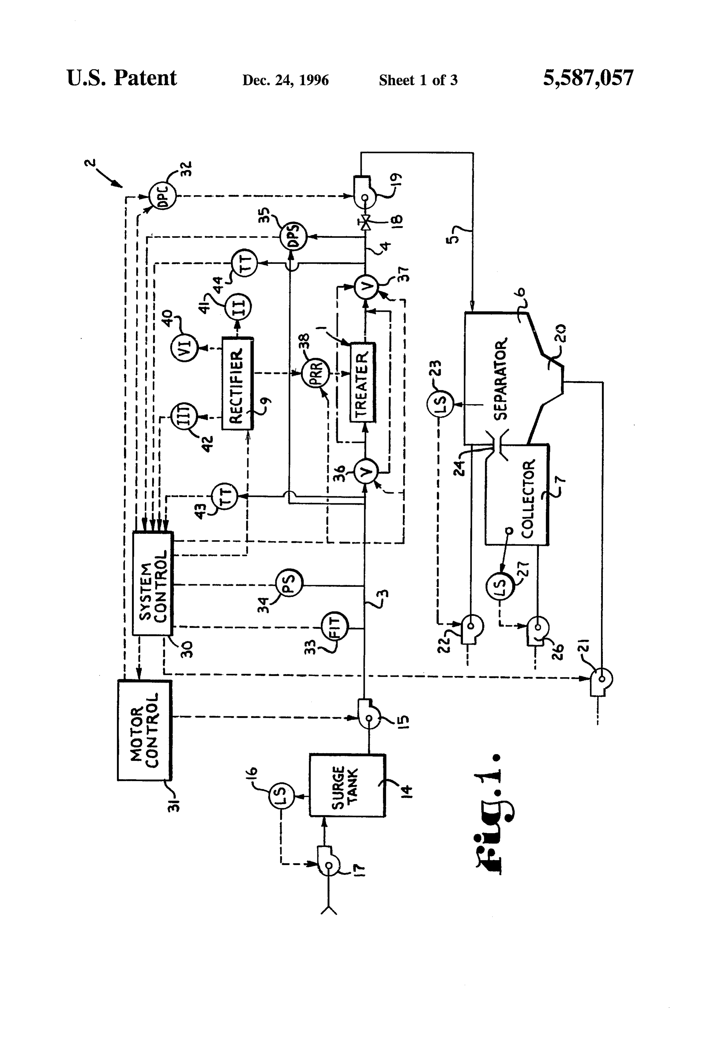
Sections of liquid are summed in series to control the current BRIEF DESCRIPTION OF THE DRAWINGS flow from the power supply; to provide treater apparatus for FIG. 1 is a block diagram of a process employing an clectrolytically treating high conductivity liquid media of 35 apparatus for highly conductive liquid media electrocoagul both low viscosities and moderate viscosities, such as oils,
Suspensions of oils and fats, suspensions of sludges, and the lation for removal of contaminants from liquid media which like; to provide such a treater apparatus including internal embodies the present invention.
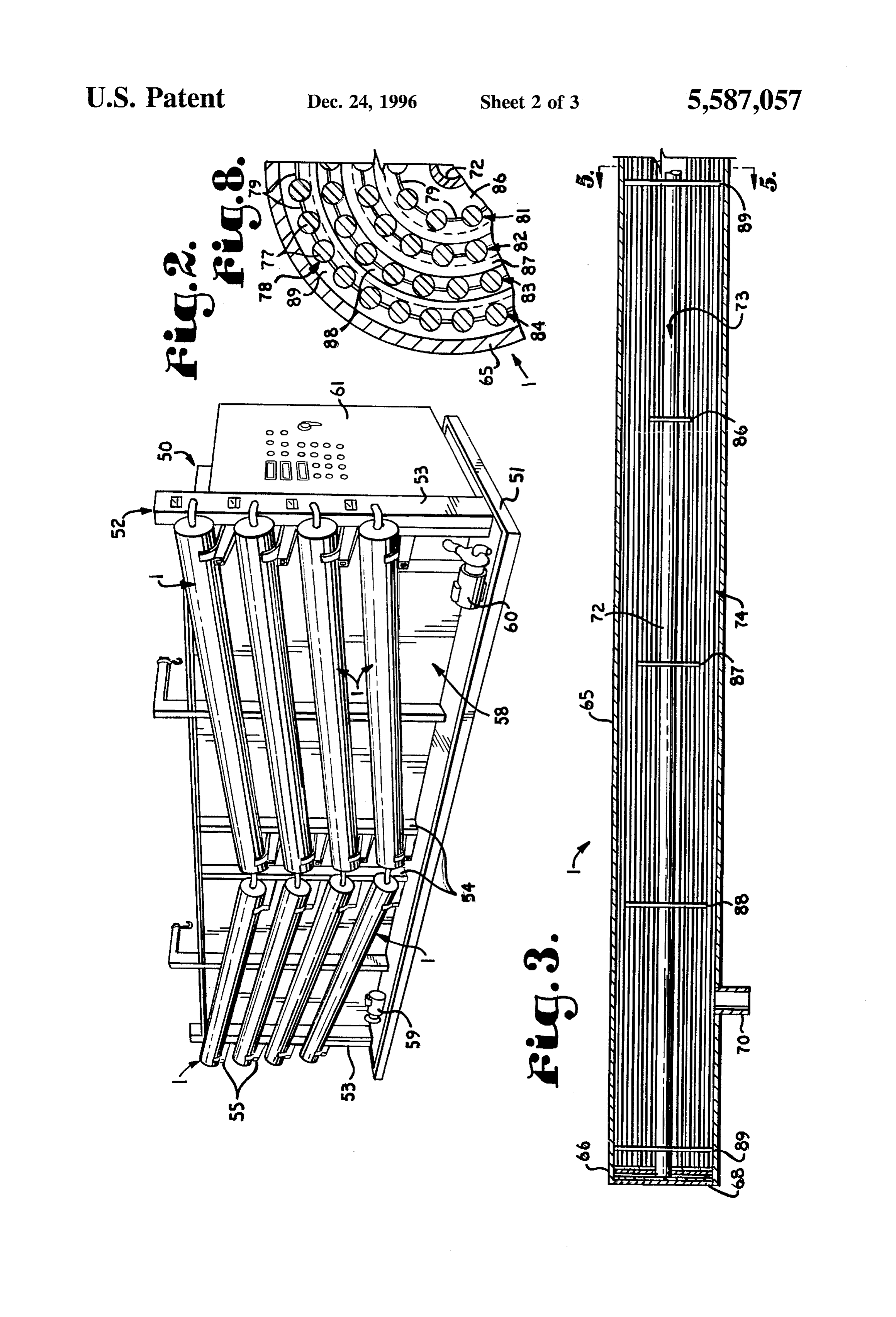
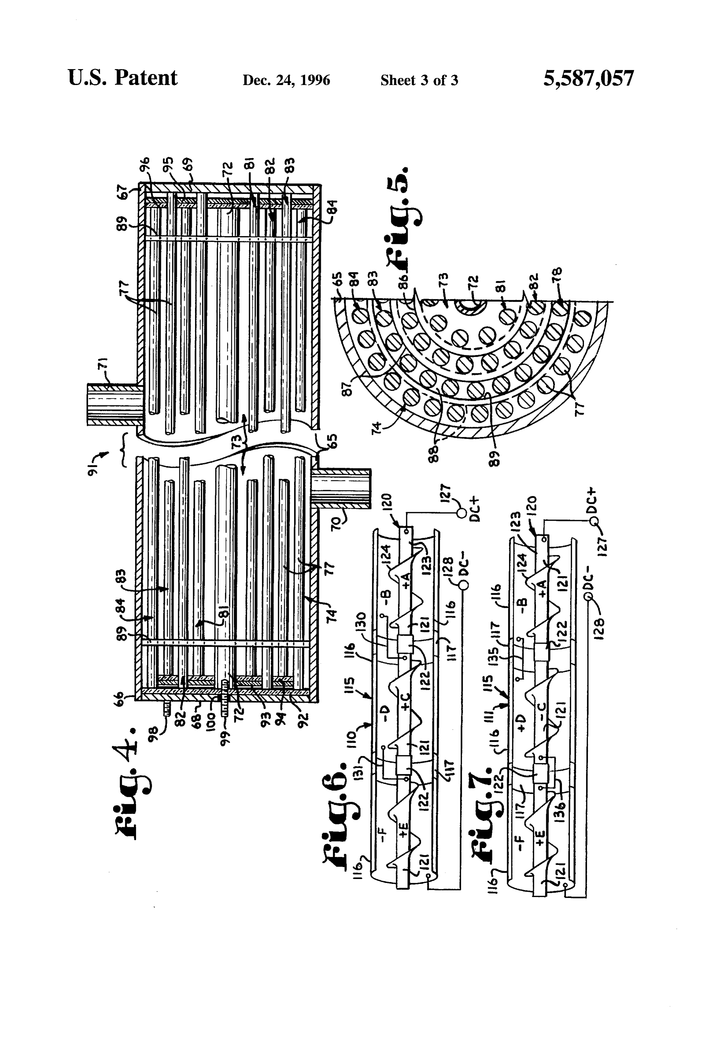
mcans for causing turbulence in liquid media flowing there FIG. 2 is a perspective view of an embodiment of appa through to promote more complete treatment of such media; 40 ratus for practicing the process of FIG. 1 for highly con to provide a treater apparatus for low viscosity liquid media ductive liquid media electrocoagulation. which is formed of an elongated cylindrical housing forming FIG. 3 is a fragmentary diagrammatic longitudinal sec an outer electrode, a center rod forming an inner electrode, tional view of an electrocoagulation treater for highly con and concentric rings of axially extending and circumferen ductive media for use in the process of FIGS. 1 or 2. tially spaced conductive rod elements, the rods in each ring 45 FIG. 4 is a greatly enlarged fragmentary diagrammatic electrode being interconnected; to provide such a treater longitudinal sectional view of the treater illustrated in FIG. apparatus wherein the ring electrodes are not connected 3 and showing components of the treater in greater detail. directly to the power supply terminals but are connected FIG. 5 is a further enlarged half transverse sectional view indirectly through the conductive liquid within the treater to taken on line 5-5 of FIG. 3 and illustrates details of the housing and center electrode whereby the ring electrodes 50 electrode rod elements and spacer members of the treater. define sections of liquid with the resistances of the sections FIG. 6 is a fragmentary diagrammatic longitudinal sec placed in series across the power supply voltage to thereby tional view of a first modified embodiment of an electroco divide the power supply voltage; to provide a modified embodiment of such a treater apparatus for liquid media of agulation treater for highly conductive liquid media employ moderate conductivities in which the ring electrodes are 55 ingFIG. an auger shaped inner electrode structure. 7 is a view similar to FIG. 6 and illustrates modified connected in alternation to the housing and center electrodes embodiment of the treater of FIG. 6 with an alternative to provide electric fields of spatially alternating polarity; to provide such treater apparatus having rings of axially electrical interconnection arrangement. extending rods wherein the rods are held in position by FIG. 8 is a view similar to FIG. 5 and illustrates details of annular baffle members which are positioned to cause tur 60 electrical interconnection of the rod elements of the ring bulence within the flowing liquid media; to provide embodi electrodes.
ments of such an electrolytic treater for high conductivity DETAILED DESCRIPTION OF THE media which are particularly adapted for treating liquid INVENTION media of moderate viscosities; to provide such treater appa ratus including an elongated cylindrical housing forming an 65 As required, detailed embodiments of the present inven outer electrode and an inner electrode having a shape tion are disclosed herein; however, it is to be understood that resembling an auger formed by a center rod with flighting the disclosed embodiments are merely exemplary of the
Page 8
invention, which may be embodied in various forms. There tank 6. Conversely, if the coalesced contaminants float, the fore, specific structural and functional details disclosed effluent is below the floc. In situation where some contami herein are not to be interpreted as limiting, but mercly as a nants settle while others float, the efflucnt is between the basis for the claims and as a representative basis for teaching contaminant levels. A collector tap 24 is positioned to flow one skilled in the art to variously employ the present the clarified effluent into the collector tank 7 where it may invention in virtually any appropriately detailed structure. be pumped by a collector pump 26, as controlled by a level Referring to the drawings in more detail: switch 27, to a site of disposal such as a waterway if permitted or to a process for further treatment if necessary,
The reference numeral 1 generally designates an electro or the effluent may be recycled to an industrial process from lytic coagulation or electrocoagulation apparatus which 10 which it was received.
cmbodies the present invention. The apparatus 1 is in an The process 2 is monitored and controlled by a system electrocoagulation treatment process or system 2 illustrated controller 30 which may be in the nature of a conventional in FIG. 1 for the flocculation of contaminants in liquid media personal computer with appropriate software and interfaces and the removal of the flocculated contaminants from the or a dedicated type of computer, such as a programmable liquid media. In general, the treater apparatus or treatcr 1 15 controller (PLC). The supply and discharge pumps 15 and receives a solution having the contaminants therein from a 19 are controlled by way of a main motor control circuit 31, supply conduit 3 and discharges the solution through dis with finer adjustments to the operation of the discharge charge conduits 4 and 5 to a separator tank 6 wherein pump 19 provided by a discharge pump control (DPC) mechanical separation of the contaminants is facilitated by circuit 32. The system controller 30 receives inputs from the coalescence of the contaminants. The coalesced contami supply conduit 3 by way of a flow indicator transmitter (FIT) nants, depending on the specific gravity of the particular 20 33 and a pressure switch (PS) 34. A differential pressure contaminants, may be separated by settling or by flotation in switch (DPS) 35 is adjusted to sense a selected pressure the separator tank 6. The clarified cffluent is drawn from the differential between the supply conduit 3 and the discharge Separator tank or separator 6 into a collector tank 7 and, if conduit 4 and sends a signal to the controller 30 upon the sufficiently purified, may be recycled or sent to an outflow 25 pressure differential exceeding the set point, thereby indi cating clogging. This causes the controller 30 to change the such as a stream or river or, if necessary, is sent to another state of a supply valve 36 and a discharge valve 37 to reverse process (not shown) for further treatment. The removed flow direction through the treater 1. At the same time, a contaminants, depending on their nature, may also be polarity reversing relay (PRR) 38 is controlled to change its recycled. The treater apparatus 1 of the present invention is state so that the polarities of the electrodes of the treater 1 particularly adapted for treating liquid media having a high 30 are reversed.
electrical conductivity. The rectifier or DC power supply 9 is provided with a A major problem in the electrolytic treatment of highly local voltage indicator (VI) 40 and a local current indicator conductive liquid media is the tendency of the media to draw (II) 41 as well as a current indicator transmitter (IIT) 42 high levels of current, or even short circuit, the power supply which allows the controller 30 to monitor current flow or rectifier 9 of the process 2. In addition to the possible 35 through the treater 1. Temperature transmitters (TT) 43 and occurrence of damage to the power supply 9 and accelerated 44 monitor the temperature of liquid entering and exiting the deterioration or consumption of the electrodes within the treater 1. The controller 30 monitors the temperature rise of treater 1 from relatively high current levels, it is important liquid passing through the treater 1 as one basis for control to control the level of current flow through the treater 1 ling the current output of the rectifier 9 to thereby control the because some contaminants are coagulated more effectively 40 electrical efficiency of the process 2. In most cases, a current at relatively lower levels of current flow. In the treater 1 of level which causes heating of the treated liquid beyond a the present invention, the level of current draw is controlled selected amount is wasteful, and the current output of the to some extent by the use of multiple section electrodes rectifier 9 is lowered accordingly. On the other hand, if the which, with media to be treated in the treater 1, divide the process 2 is intended to destroy biological contaminants in output voltage of the power supply 9 across multiple resis 45 the treated liquid, then the rectifier 9 is controlled to a tance sections formed by corresponding electrode sections maintain a desired temperature rise. and portions of the liquid media to thereby lower the current FIG. 2 illustrates an exemplary embodiment of major draw from the power supply 9. portions of the electrolytic liquid media treatment process 2 Referring to FIG. 1, the supply conduit 3 receives liquid shown in FIG. 1. The process assembly 50 includes a base to be treated from a surge tank 14 through a supply pump 15. 50 51 with a framework 52 extending upwardly therefrom. The level within the surge tank 14 is controlled by a level Corner standards 53 and medial standards 54 of the frame switch 16 controlling a fill pump 17 which receives the work 52 have a plurality of outwardly extending arms 55 liquid from an external source, such as another industrial which support a plurality of treater apparatus or treaters 1. process (not shown). On the discharge side of the treater 1, The treaters 1 may be fluidically connected in series, in a pressure throttle 18 in the discharge conduit 4 cooperates 55 parallel, or in various types of series-parallel arrangements with the supply pump 15 and a discharge pump 19 to control according to the requirements of the process 2 and the the flow of the liquid through the treater 1. The discharge character of the contaminants in the liquid media being pump 19 feeds the separator 6 through the outer discharge treated. The framework 52 also supports a tank 58, such as conduit 5. the surge tank 14 of FIG. 1, which holds a quantity of the The separator 6 may be an inclined plate separator or 60 liquid to be treated. Pumps 59 and 60 (plumbing not shown) clarifier which collects denser sludge to a lower trough 20 are provided on the base 51 and correspond respectively to from which the sludge may be drawn off by a sludge pump the supply pump 15 and the discharge pump 19 of FIG. 1. 21 to a collection vessel for further processing, recycling, Finally, the framework 52 supports a control housing 61 disposal, or the like. Lighter floc may be skimmed off the top which houses the system controller 30, the rectifier or power of the separator 6 by a skim pump 22 as controlled by a level 65 supply 9, and other instrumentation of the process 2. switch 23. In a liquid in which the coalesced contaminants FIGS. 3-5 illustrate a preferred embodiment of the treater settle out, the clarified effluent is at the top of the separator apparatus 1 of the present invention. The treater 1 generally
Page 9
includes an elongated cylindrical housing 65 which is closed 78 depends on its relative proximity to the housing 65 and all opposite ends 66 and 67 by respective end walls 68 and center electrode 72 and the resistance of the annular layers 69 (FIG. 4). The housing 65 has first and sccond fluid of fluid between the given ring electrode 78 and the housing connections 70 and 71, either of which may function as an 65 and center electrode 72. Since the rods 77 of a ring inlet connection or an outlet connection. A center electrode electrode 78 are mutually interconnected, all such rods 77 rod or tube 72 extends axially through the housing 65. The have the same polarity and magnitude of voltage. housing 65 and center rod 72 are formed of conductive The rods 77 and their arrangement in the ring electrodes matcrials. The materials from which the housing 65 and 78 controls the current flow between the housing 65 and the center rod 72 are constructed need not be the same. The clongated annular space between the center rod 72 and center electrode 72 to a substantially radial direction housing 65 comprises a treater or treatment chamber 73 and 10 whereby the sum of the resistances of the layers of liquid is occupical by an electrode structure 74, as will be detailed between the housing 65 and center electrode 72 is applied below. across the output voltage of the power supply 9. Without the rods 77 arranged in the ring electrodes 78, the current from
The electrode structure 74 is formed by a plurality of the power-supply axially extending electrode elements or rods 77 which 9 may be confined to a small area where 5 the center electrode 72 is closest to the housing 65, such as extend parallel to the center rod 72. The rods 77 are preferably arranged in circumferentially spaced relation to in an area in which the center electrode 72 droops toward the form concentric rings which are positioned in coaxial rela housing 65 under the influence of gravity. tion with the center rod 72. The rods 77 within a given ring The treater 1 of a general configuration as shown in FIG. arc interconnected clectrically to define a ring electrode 78 20 3 with the rods 77 of each ring electrode 78 mutually (FIGS. 5 and 8), as by wires or conductive bars 79. Alter interconnected, but wherein the ring electrodes 78 are not natively, other means may be employed to interconnect the directly connected to the power supply 9, is appropriate for rods 77 comprising the ring electrodes, such as conductive treating liquid media of very high conductivity. The general means (not shown) incorporated into the baffles 86-89. In configuration of such a treater is also useful for treating the illustrated treater 1, there are four ring electrodes posi 25 liquid media of somewhat lower conductivity where it is tioned coaxially: 81, 82, 83, and 84. The rods 77 of the ring also desirable to subject the liquid to electric fields of clectrodes 78 are held in place by respective annular baffles spatially reversing polarity, by the manner of interconnec through which the rods 77 extend. At least two baffles are tion of the rods 77 in a modified treater apparatus 91 shown associated with each ring electrode 78. The rods 77 of the in FIG. 4.
inner most ring electrode 81 are mounted in baffles 86. 30 The rods 77 of ring electrodes 82 and 84 extend on the left Similarly, the rods 77 of ring electrodes 82, 83, and 84 are (as viewed) to an end insulation plate 92 and are intercon mounted respectively in baffles 87, 88, and 89. nected with the center electrode 72, as by being welded to The annular baffles 86-89 are preferably formed of an a connection plate 93. The leftmost ends of the rods 77 of the insulating and chemically inert material, such as certain ring electrodes 81 and 83 are insulated from the connection kinds of synthetic resins. The baffles 86-89 are sized so that 35 plate 93 by an insulation plate 94. Similarly, at the right end their inner and outer edges engage the rods 77 of radially of the treater 91, the rightmost ends of the rods 77 of the ring adjacent ring electrodes 78. An inner edge of the inner baffle electrodes 81 and 83 extend to the end plate 69 of the 86 cngages the center electrode 72, and an outer edge of the housing 65 and are interconnected, as by being welded to a outer baffle 89 engages the inner surface of the housing 65. connection plate 95. The rightmost ends of the rods 77 of the The engagement of the edges of the baffles 86-89 with the 40 ring electrodes 82 and 84 are insulated from the connection rods 77 in multiple places provides additional positional plate 95 by an insulation plate 96. A housing terminal 98 is stability to the rods 77, which may be somewhat flexible, provided on the end plate 68, and a center electrode terminal and reduces variations in the spacing between the rods 77 of 99 extends through an insulating bushing 100 to the center the various ring electrodes 78. electrode 72. By this arrangement, the housing 65 and ring The members 86-89 are referred to as baffles because, in 45 electrodes 83 and 81 are connected to one pole of the power addition to support functions, the members 86-89 are supply 9, and the center electrode 72 and the ring electrodes intended to affect the flow of liquids through the treater 82 and 84 are connected to an opposite pole of the power chamber 73. Liquids flowing through the treater 1 are forced supply 9. The polarities of the electric fields between adja around the baffles 86-89 thereby introducing turbulence in cent ring electrodes 78 reverses from one annular section the liquids which promotes mixing of portions which have 50 between a set of ring electrodes 78 and the next radially received various degrees of electrolytic treatment. Such adjacent section. The baffles 86-89 force liquid media mixing results in more even and complete treatment of the flowing through the treater 91 to move radially between the liquid media flowing through the treater 1. ring electrodes 81–84 to provide even treatment of the With a conductive liquid in the treater chamber 73 and a liquid.
DC voltage applied from the rectifier or power supply 9 to 55 The treater 1 of FIGS. 3 and 8 and the treater 91 of FIG. the housing 65 and center electrode 72, electrical currents 4 are intended for the electrolytic treatment of liquids having flow between the housing 65 and center electrode 72 in a low viscosities. FIGS. 6 and 7 diagrammatically illustrate direction which depends on the polarity of the power supply treaters 110 and 111 respectively which are intended for connections thereto. The ring electrodes 78, in effect, form treating liquids of moderate viscosity and relatively high "foraminous" or porous cylindrical electrodes through 60 conductivity, such as some sludges and oils carrying con which the liquid media can flow and function to distribute taminants which render them highly conductive. The treaters and even out the flow of current through the liquid. Since the 110 and 111 are structurally similar, but components thereof rods 77 of a given ring electrode 78 are not connected are interconnected differently. The same reference numerals directly to the power supply 9, the voltage applied to the will be used in FIGS. 6 and 7 for comparable components. housing 65 and center electrode 72 is applied to the rods 77 65 Each of the treaters 110 and 111 is formed by an elongated by conduction through the liquid media. The polarity and cylindrical outer housing 115, which may be similar to the magnitude of voltage on the rods 77 of a given ring electrode housing 65 of the treaters 1 and 91, as far as fluidic
Page 10
considerations are concerned. In the treaters 110 and 111, positive with respect to housing section B, electrode section each housing 115 is formed by conductive housing sections C is negative with respect to housing section D, and elec 116 which are connected in line by insulative housing trode section E is positive with respect to housing section F. section connectors 117. An clectrode structure 120 is posi Thus, clectric fields of spatially reversing polarities arc tioned coaxially within the housing 115. The electrode experienced by a liquid passing through the treater 111. structure 120 is formed of conductive electrode sections 121 While the term "housing' may appear to be contrasted which are connected in line by insulative clectrode section with the term "electrode' herein, it should be understood connectors 122. The illustrated electrode structure 120 has that the housings described in connection with the treaters 1, the appearance of an auger, and each electrode section 121 91, 110, and 111 also function as electrodes. The materials is formed by a center rod 123 with a conductive vanc or 10 from which the electrode elements of the treaters 1,91, 110, flighting 124 wrapped helically thereabout to form, in effect, and 111 are formed are selected according to the types of a closed helical structure. The flighting 124 causes turbu contaminants and carrier liquids involved in the electroco lence in a liquid flowing through the treaters 110 or 111 to agulation processes. In some cases, the electrode materials mix portions of the liquid, to thereby promote more even are chemically involved in the electrocoagulation reactions, treatment of the liquid media. whereby the portions of the electrodes are consumed. In The electrode sections 121 arc labeled A, C, and E; and 15 other cases, the electrode materials function catalytically. the housing sections 116 are labeled B, D, and F. Addition Finally, the electrode materials may not react chemically at ally, cach of the sections 116 and 121 carries a polarity all with the contaminants or solvents containing them. indicator (a plus or a minus symbol) based on the manner of It is to be understood that while certain forms of the connection of components of the treaters 110 and 111 to a 20 present invention have been illustrated and described herein, positive DC power supply terminal 127 and a negative DC it is not to be limited to the specific forms or arrangement of power supply terminal 128, such as the terminals of the parts described and shown.
rectifier or power supply 9 of FIG. 1. What is claimed and desired to be secured by Letters The treater 110 of FIG. 6 is intended for the treatment of Patent is as follows:
liquid media which do not benefit, as far as electrocoagul 25 prising:1. An electrolytic treater apparatus for liquids and com lation properties, from travel through electric fields of spa tially reversing polarities. As in the treater 1, the treater 110 (a) an elongated tubular housing formed of conductive is intended for treatment of liquid media having high con material and closed at opposite ends to form an elon ductivity such that it is desirable to apply the power Supply gated treater chamber;
voltage across substantial portions of the liquid media to 30 (b) means forming a first fluid connection and a second increase the resistance presented to the power supply 9. This fluid connection positioned respectively adjacent said is accomplished in the illustrated treater 110 by connecting opposite ends and defining a flow path through said the positive power supply terminal 127 to the electrode treater chamber, section A, connecting the corresponding housing section B (c) power supply means having a first power supply to the next adjacent electrode section C by a conductor 130, 35 terminal and a second power supply terminal of oppo connecting the housing section D to the electrode section E site polarities and having an output voltage; by a conductor 131, and connecting the housing section F to (d) an elongated electrode structure extending through the negative power supply terminal 128. While the illus said chamber, said electrode structure having multiple trated treater 110 shows only three such sets of sections, the conductive sections insulated from one another, pattern would be the same for any number of sets of sections. 40 (e) said power Supply means being connected to said It can be demonstrated, using conventional DC circuit housing and said electrode structure in such a manner analysis, that with such a connection pattern, electrode that, with a conductive liquid present in said chamber, sections A, C, and E will all be positive with respect to said output voltage is divided across said electrode housing sections B, D, and F, whereby no polarity reversals structure Sections; and of electric fields will be experienced by a liquid travelling 45 through the treater 110. (f) flow reversing valve means fluidically connected to In contrast to the treater 110, the treater 111 is intended for said first and second fluid connections and being reversibly operable to flow a fluid through said flow treating liquid media in which the contaminants are more path in a first direction from the first connection to the readily electrocoagulated by passage of the media through second connection or in the reverse direction from the electric fields of reversing polarity. In the illustrated treater 50 second connection to the first connection. 111, the positive power supply terminal 127 is connected to 2. An apparatus as set forth in claim 1 and including: electrode section A, corresponding housing section B is connected to adjacent housing section D by a conductor 135; (a) differential pressure sensor means connected to mea electrode section C is connected to adjacent electrode sec sure a pressure differential between liquid entering said tion E, and housing section F is connected to the negative 55 first fluid connection and liquid exiting said second power supply terminal 128. It should be noted that with an fluid connection; and odd number of sets of sections 116 and 121, one power (b) control means connected to said differential pressure supply terminal will be connected to an end electrode sensor means and operative to activate said flow revers section and the opposite power supply terminal will be ing valve means in response to the measured differen connected to an end housing section. However, with an even 60 tial pressure exceeding a selected value. number of sets of sections 116 and 121, both power supply 3. An electrolytic treater apparatus for liquids and com terminals will be connected to the same type of end sections, prising:
either both end electrode sections 121 or both end housing (a) an elongated tubular housing formed of conductive sections 116. material and closed at opposite ends to form an elon It can be demonstrated, using conventional DC circuit 65 gated treater chamber;
analysis, that with the connection pattern described and (b) means forming a first fluid connection and a second shown in FIG. 7 for the treater 111, electrode section A is fluid connection positioned respectively adjacent said
Page 11
opposite ends and defining a flow path through said (c) power supply means having a first power supply trcater chambcr; terminal and a second power supply terminal of oppo (c) power supply means having a first power supply site polarities and having an output voltage; terminal and a second power supply terminal of oppo (d) an elongated electrode structure extending through sitc polarities and having an output voltage; said chamber, said electrode structure having multiple (d) an clongated electrodc structure extending through conductive sections insulated from one another, said chamber, said electrode structure having multiple (e) said power supply means being connected to said conductive sections insulated from onc another, electrode structure in such a manner as to provide (c) said power supply means being connected to said electric fields of spatially reversing polarity to a liquid housing and said electrode structure in such a manner O passing through said chamber; that, with a conductivc liquid present in said chamber, (f) temperature differential sensor means connected to said output voltage is divided across said electrode measure a temperature differential between liquid structure sections; entering said first fluid connection and liquid exiting (f) tempcrature differential sensor means connected to said second fluid connection; and measure a temperature differential between liquid 15 (g) control means connected to said power supply means, entering said first fluid connection and liquid exiting having said temperature sensor means connected said second fluid connection; and thereto, and controlling a current flow between said (g) control means connected to said power supply means, terminals in response to the measured temperature having said temperature sensor means connected differential.
thereto, and controlling a current flow between said 7. An electrolytic treater apparatus for liquids and com terminals in response to the measured temperature prising:
differential. (a) an elongated tubular housing formed of conductive 4. An electrolytic treater apparatus for liquids and com material and closed at opposite ends to form an elon prising: gated cylindrical treater chamber, (a) an elongated tubular housing formed of conductive 25 (b) means forming a first fluid connection and a second material and closed at opposite ends to form an elon fluid connection positioned respectively adjacent said gated treater chamber; opposite ends and defining a flow path through said (b) means forming a first fluid connection and a second treater chamber;
fluid connection positioned respectively adjacent said 30 (c) an elongated center electrode assembly positioned opposite ends and defining a flow path through said coaxially within said cylindrical chamber, said elec treater chamber; trode assembly being formed of conductive material (c) power Supply means having a first power supply and having a closed helical shape; terminal and a second power supply terminal of oppo (d) power supply means having a pair of terminals of site polarities and having an output voltage; 35 opposite polarity, one of said terminals being connected (d) an elongated electrode structure extending through to said housing and the other of said terminals being said chamber, said electrode structure having multiple connected to said electrode; and conductive sections insulated from one another, (e) flow reversing valve means fluidically connected to (c) said power supply means being connected to said said first and second fluid connections and being clectrode structure in such a manner as to provide 40 reversibly operable to flow a fluid through said flow electric fields of spatially reversing polarity to a liquid path in a first direction from the first connection to the passing through said chamber; and second connection or in the reverse direction from the (f) flow reversing valve means fluidically connected to second connection to the first connection. said first and second fluid connections and being 45 prising: 8. An electrolytic treater apparatus for liquids and com reversibly operable to flow a fluid through said fluid path in a first direction from the first connection to the (a) an elongated tubular housing formed of conductive second connection or in the reverse direction from the material and closed at opposite ends to form an elon second connection to the first connection. gated cylindrical treater chamber; 5. An apparatus as set forth in claim 4 and including: (b) means forming a first fluid connection and a second (a) differential pressure sensor means connected to mea 50 fluid connection positioned respectively adjacent said sure a pressure differential between liquid entering said opposite ends and defining a flow path through said first fluid connection and liquid exiting said second treater chamber, fluid connection; and (c) an elongated center electrode assembly positioned (b) control means connected to said differential pressure 55 coaxially within said cylindrical chamber, said elec sensor means and operative to activate said flow revers trode assembly being formed of conductive material ing valve means in response to the measured differen and having a closed helical shape; tial pressure exceeding a selected value. (d) power supply means having a pair of terminals of 6. An electrolytic treater apparatus for liquids and com opposite polarity, one of said terminals being connected prising: 60 to said housing and the other of said terminals being (a) an elongated tubular housing formed of conductive connected to said electrode; material and closed at opposite ends to form an elon (e) flow reversing valve means fluidically connected to gated treater chamber; said first and second fluid connections and being (b) means forming a first fluid connection and a second reversibly operable to flow a fluid through said flow fluid connection positioned respectively adjacent said 65 path in a first direction from the first connection to the opposite ends and defining a flow path through said second connection or in the reverse direction from the treater chamber; second connection to the first connection;
Page 12
(f) differential pressure sensor means connected to mea trode assembly being formed of conductive material sure a pressure differential between liquid entering said and having a closed helical shape; first fluid connection and liquid exiting said second (d) power Supply means having a pair of terminals of fluid connection; and (g) control means connected to said differential pressure opposite polarity, one of said terminals being connected sensor means and operative to activate said flow revers to said housing and the other of said terminals being ing valve means in response to the measurcd differen connected to said electrode assembly; tial pressure exceeding a selected value. (c) temperature differential sensor means connected to 9. An electrolytic treater apparatus for liquids and com measure a temperature differential between liquid prising: O entering said first fluid connection and liquid exiting (a) an elongated tubular housing formed of conductive said second fluid connection; and material and closed at opposite ends to form an elon gated cylindrical treater chamber; (f) control means connected to said power Supply means, (b) means forming a first fluid connection and a second 15 having said temperature sensor means connected fluid connection positioned respectively adjacent said thereto, and controlling a current flow between said opposite ends and defining a flow path through said terminals in response to the measured temperature treater chamber, differential.
(c) an elongated center electrode assembly positioned coaxially within said cylindrical chamber, said clec
Provenance
- Collection
- Cited prior art
- Original PDF
- patentimages.storage.googleapis.com →
- Filed
- 1993-12-07
- Pages
- 12
- Method
- pdftotext (the PDF's own text layer) + pdftoppm 300dpi page scans
- Source
- Google Patents bibliographic record
- Granted
- 1996-12-24
- Inventors
- David M. A. Metzler; Albert L. Mauk
- Transcribed from
- patentimages.storage.googleapis.com →