patent · US5408970
Electronically controlled continuous flow fuel system
25 April 1995
Page 1 — bibliographic record
United States Patent (19) 11 Patent Number: 5,408,970 Burkhard et al. 45 Date of Patent: Apr. 25, 1995 54 ELECTRONICALLY CONTROLLED 4,676,214 6/1987 Kato et al. .......................... 123/447 CONTINUOUS FLOW FUEL SYSTEM Primary Examiner-Carroll B. Dority 75 Inventors: James F. Burkhard, Spencerport; Attorney, Agent, or Firm-Karl F. Barr, Jr. Kenneth J. Dauer, Avon; William H. 57 ABSTRACT
Pettit, Rochester, all of N.Y.
An electronically controlled fuel system for use with a 73) Assignee: General Motors Corporation, Detroit, continuous, non-cyclical process has a fuel manifold to Mich. which pressurized fuel from a source is supplied and 21 Appl. No.: 236,980 through which the fuel is metered, to an end use com bustor, by a periodically energizable pulse-width modu 22 Filed: May 2, 1994 lated, solenoid actuated valve. The pulsed fuel output of I51 Int. Cl°............................................. FO2M 37/00 the valve is exposed to an accumulator which operates 52 U.S. C. .................................... 123/447; 123/467; on the output to reduce the amplitude of the pulsations 431/30, 431/121 effectively integrating them out of the fuel flow, result 58) Field of Search .................. 123/447, 467; 431/30, ing in a substantially continuous supply of fuel. A purge 431/121 system may be integrated into the fuel manifold and has (56) References Cited a second solenoid actuated valve member which is op erable, upon fuel system shut-down, to direct pressur
3,777,726 12/1973 Knapp et al. ....................... 123/447 4,280,464 7/1981 Kanai et al. ......................... 123/447 3 Claims, 4 Drawing Sheets
IGNITION
MODULE
AIR
METER BLOWER
ECM
Page 2
Drawing sheet — no readable text.
Page 3
Drawing sheet — no readable text.
Page 4
Drawing sheet — no readable text.
Page 5
Drawing sheet — no readable text.
Page 6
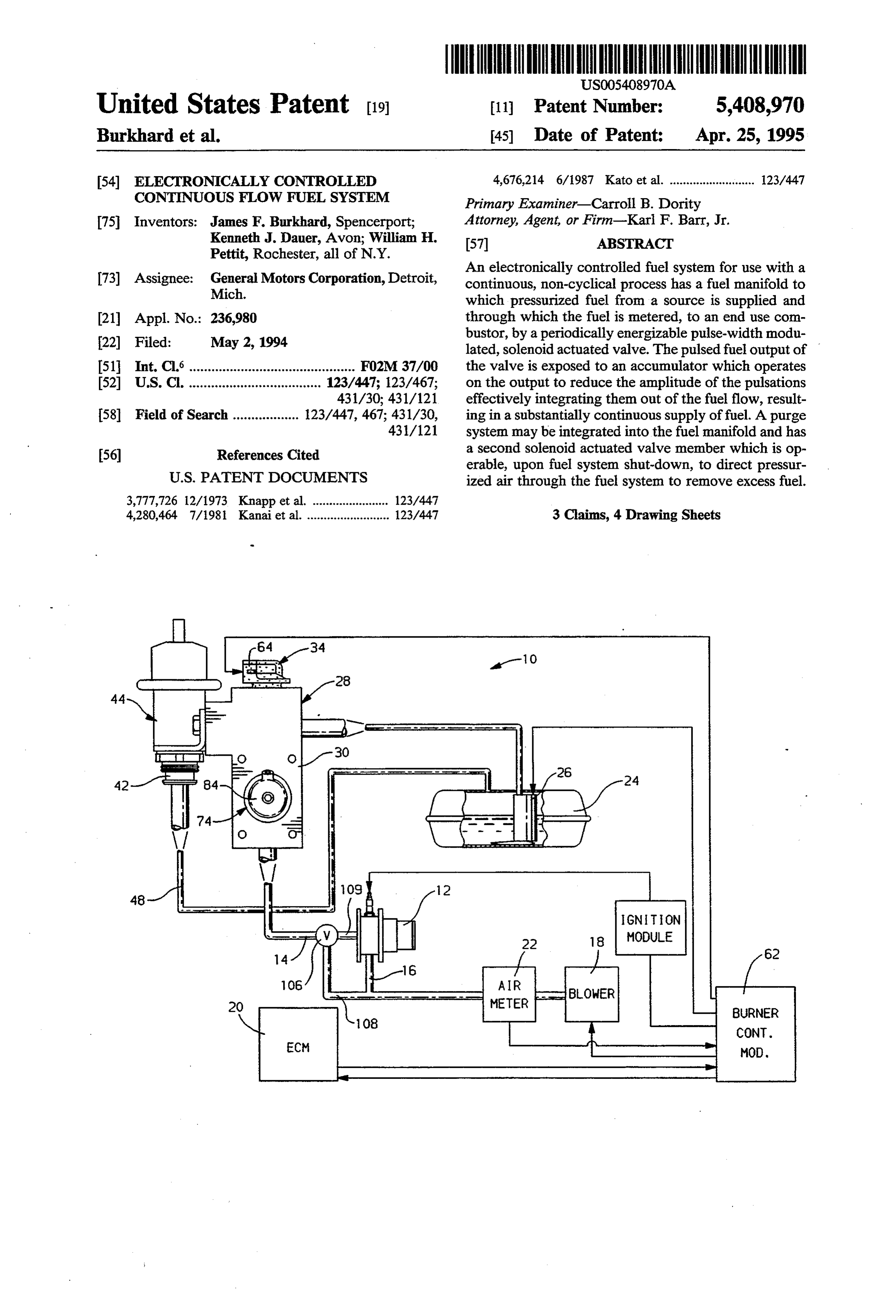
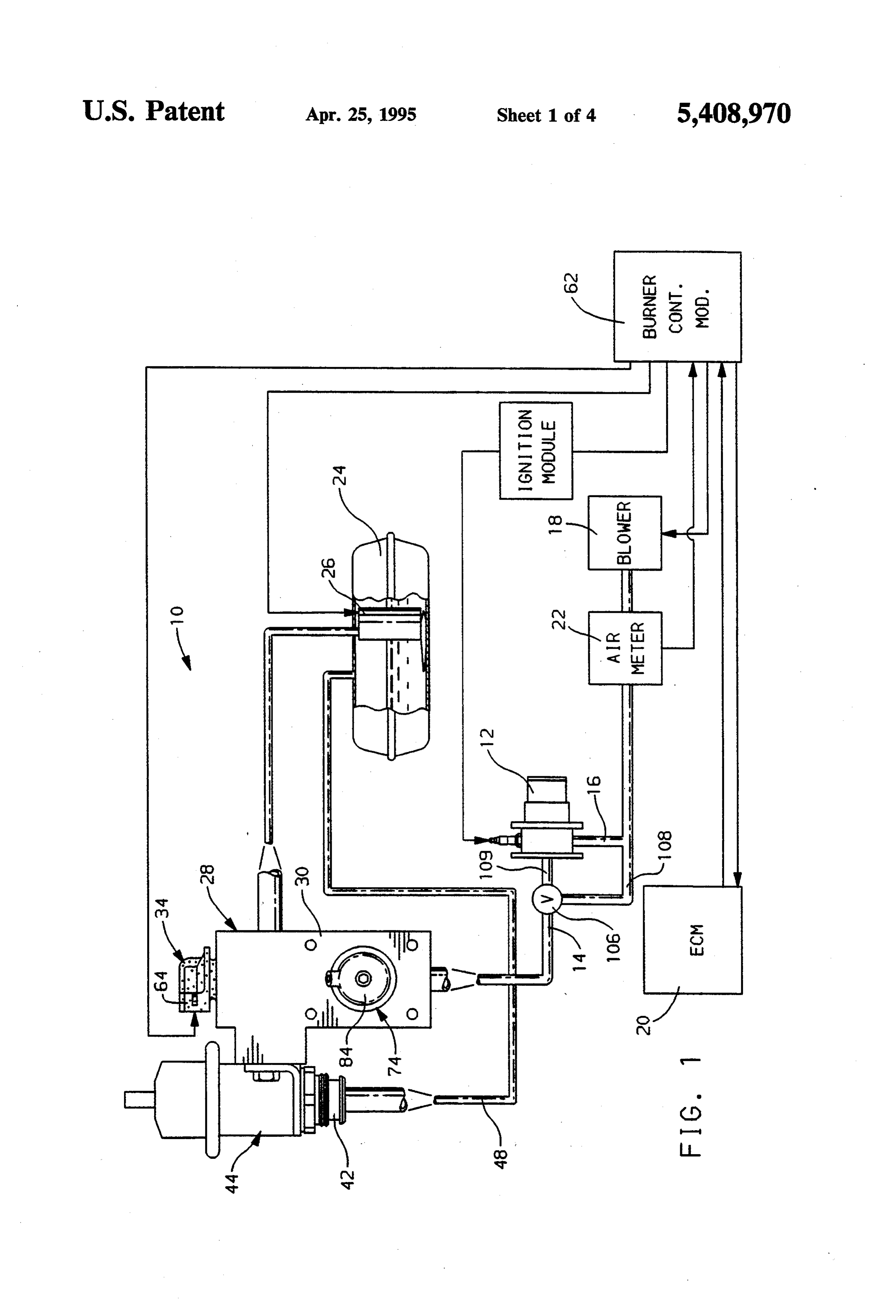
EECTRONICALLY CONTROLLED BRIEF DESCRIPTION OF THE DRAWINGS CONTINUOUS FLOW FUEL SYSTEM FIG. 1 is a schematic diagram of a fuel system em bodying features of the present invention;
TECHNICAL FIELD FIG. 2 is a plan view of the fuel manifold assembly of This invention relates to fuel systems for end-use the present invention;
devices requiring continuous flow and, in particular, to blyFIG.
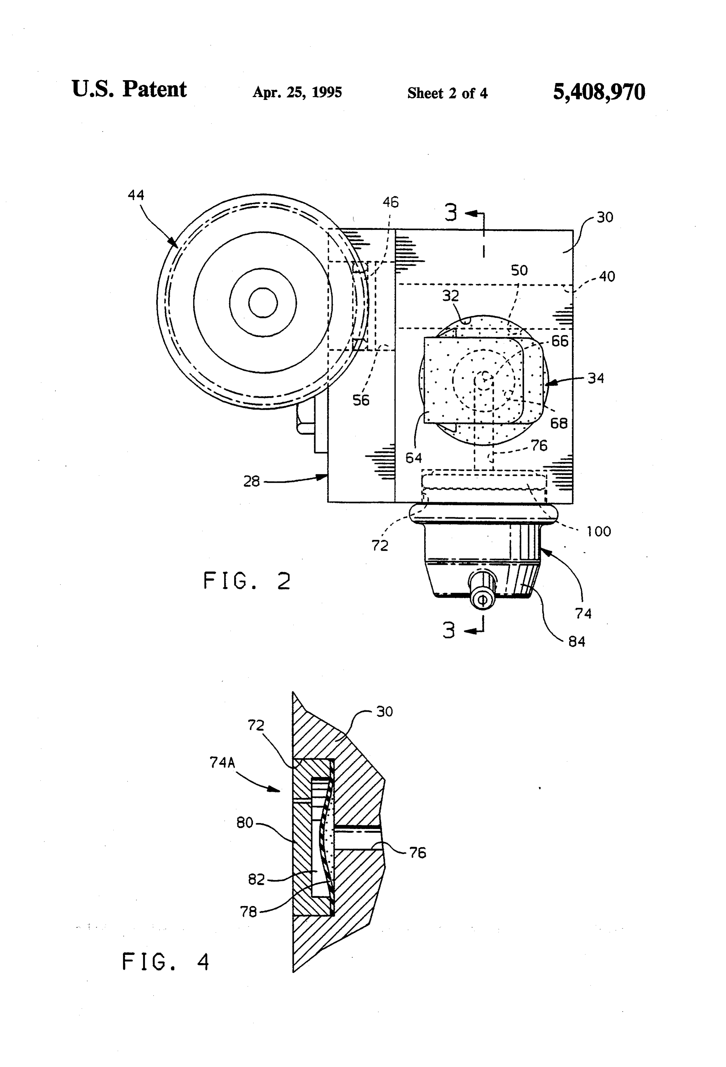
3 is a sectional view of the fuel manifold assem
FIG. 2, taken along line 3-3;
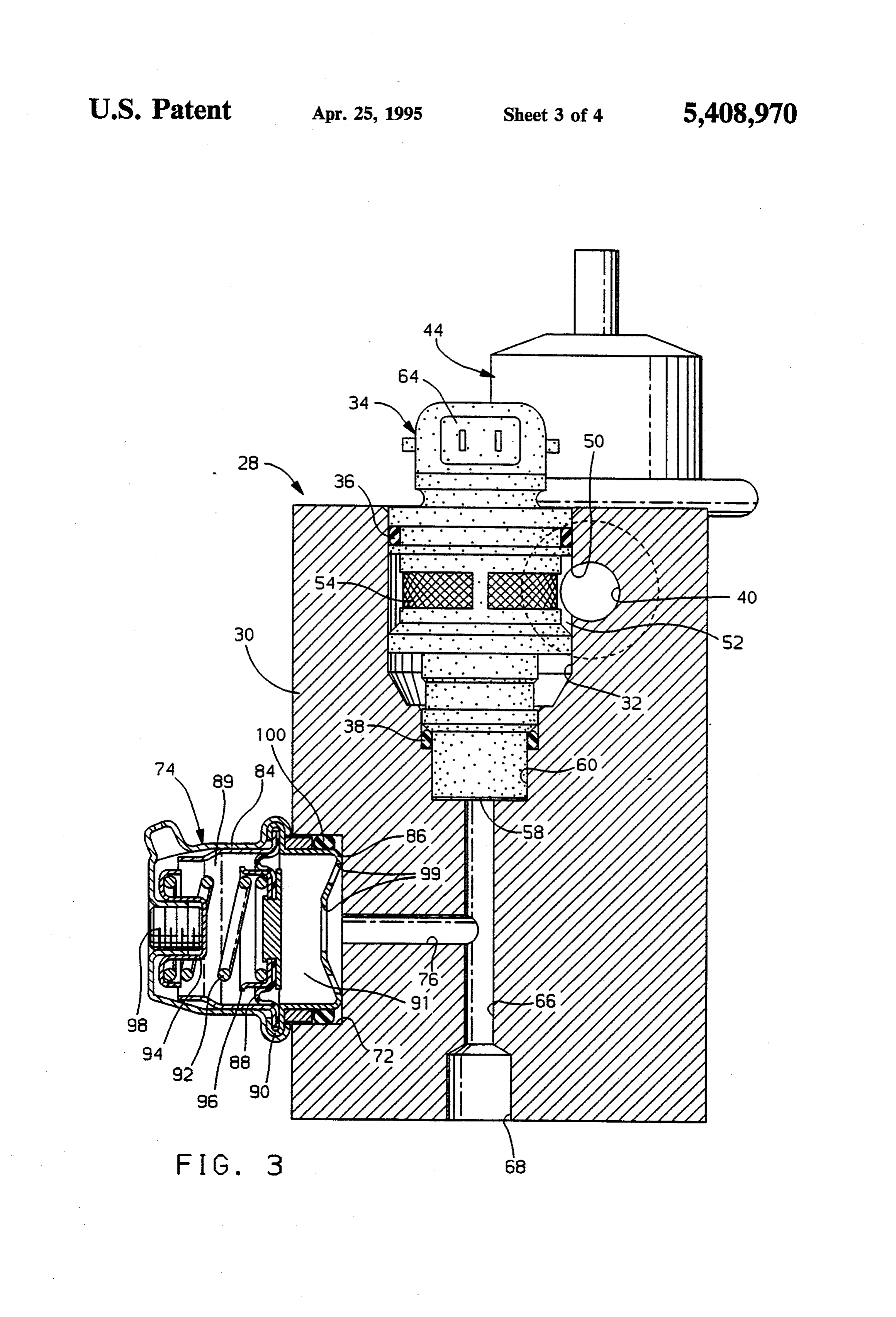
an electronically controlled, continuous flow fuel sys FIG. 4 is a partial, sectional view of one embodiment tem having an electromagnetic fuel injector for meter 10 of an accumulator, of the present invention; and ing fuel. FIG. 5 is a sectional view of a second embodiment of BACKGROUND the fuel manifold assembly of the present invention. Continuous cycle processes such as those employed DESCRIPTION OF THE PREFERRED in automotive burner applications, gas turbines, Stirling 15 EMBODIMENTS engines and steam engines typically require that fuel be In FIG. 1 there is illustrated a system layout for an supplied in precise quantities at a continuous rate of automotive burner. Such a burner may have application delivery. Conventional electromagnetic solenoid actu in the preheating of engine coolant, exhaust treatment ated valves are used to supply fuel to cyclic processes devices, or may be used to regenerate particulate traps such as Otto and Diesel engines in which an electrical used to filter the exhaust gas of certain internal combus supply current is pulse-width modulated to vary the tion engines. Such a system has numerous potential open time of the valve to correspond with engine tim configurations and components with only one such ing, performance demands, and other understood prin contemplated system shown for illustrative purposes. ciples. By varying the open time of an essentially fixed The burner system, referred to generally as 10, includes orifice, the flow rate over time can be precisely con 25 a burner or combustor 12 to which the combustion trolled. With this means of fuel delivery, however, the components of fuel and air are supplied via conduits 14 output from the valve is pulsed at the same frequency at and 16, respectively. A pressurized source for combus which the valve is operated. These pulsations are unde tion air may be blower 18 which receives a control signal from Burner Control Module (BCM) 62 based on sirable for use in continuous processes as they may 30 vehicle affect overall efficiency, increase emissions, increase from airand system inputs including flow information audible noise generated during operation and impact is drawn on by 22. meter A source of fuel such as fuel tank 24 fuel pump 26 to supply pressurized fuel robustness of the end use device.
for the combustor 12. In an automotive application, the
SUMMARY OF THE INVENTION fuel pump 26 will supply pressurized fuel not only for 35 the combustor 12, which may operate on an intermittent
The present invention is directed to an electronically basis, controlled fuel system for use with a continuous, non diesel but also for the vehicle prime mover such as a cyclical process such a an automotive burner system. the fuel pump caninternal or gasoline not be combustion engine. As such, relied on to precisely control
The subject fuel system utilizes an electromagnetic the fuel quantity, pressure and delivery of fuel to the solenoid actuated valve, such as a fuel injector, which is combustor 12.
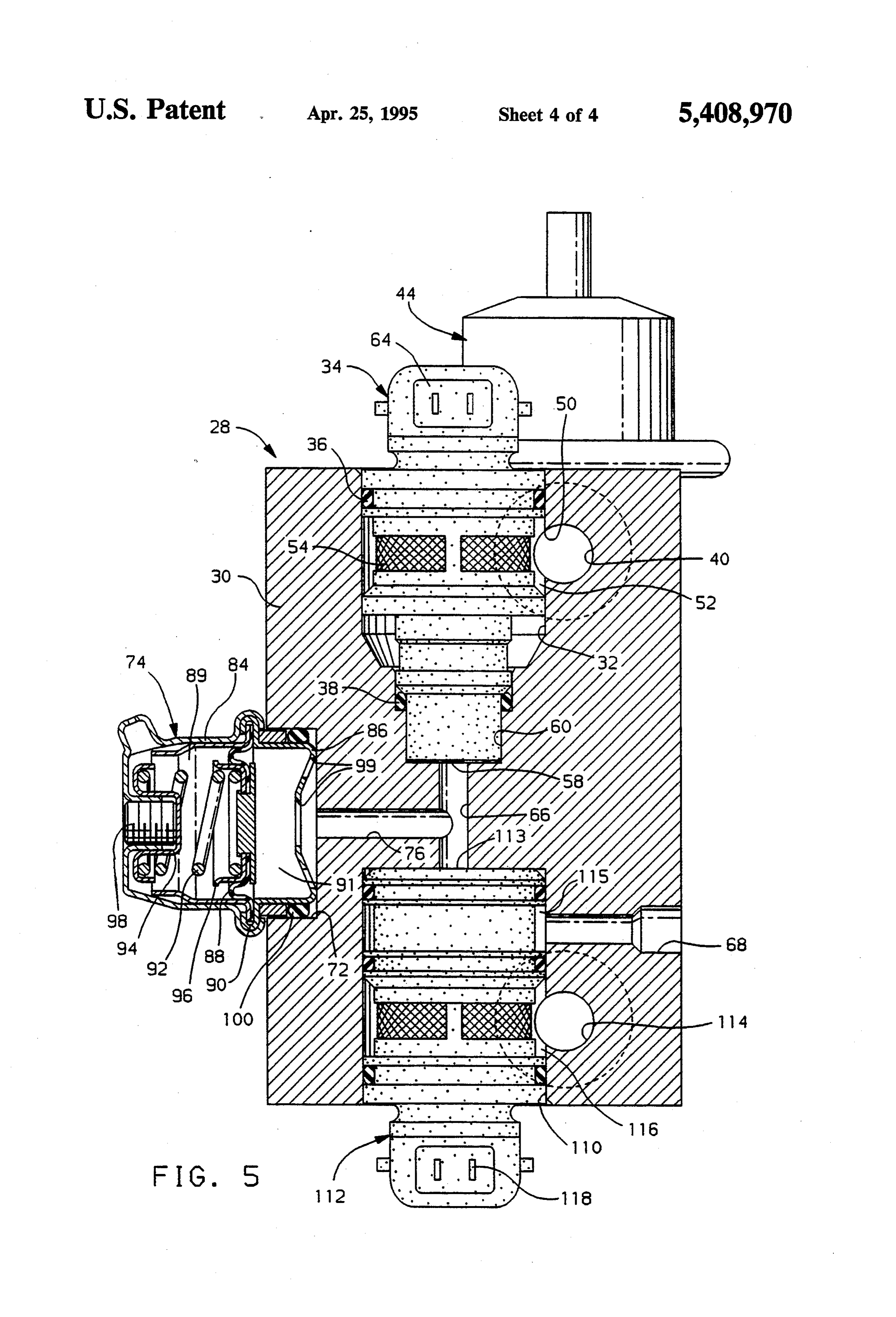
pulse-width modulated through a controller to dis A fuel manifold assembly 28, shown in FIGS. 1, 2 and charge a desired, metered quantity of fuel to the end-use 3 provides the necessary conditioning and metering of combustor. The metered and pulsed output of the injec the fuel supply from pump 26, required for optimum tor is subjected to a reduction in amplitude or severity operation of the combustor 12, or other end use device. of the pulses through the addition of an accumulator 45 The fuel manifold comprises a block 30 constructed of which is disposed between the outlet of the fuel injector material which has the appropriate durability for such a and the inlet of the combustor. The accumulator oper fuel environment. The block 30 has a first, cylindrical, ates, upon introduction of a fuel pulse, to fill with a stepped diameterbore 32 which is adapted to receive a portion of the fuel from the metered pulse of fuel while periodically energizable, electromagnetic solenoid actu directing the remainder of the metered pulse of fuel to 50 ated metering valve such as fuel injector 34. Resilient the combustor. Following the termination of the pulse, sealing members 36 and 38 are disposed between the and prior to the introduction of a subsequent fuel pulse, injector 34 and the wall of the bore 32 to prevent migra the fuel within the accumulator is discharged, to the end tion of fuel out of the injector or from the inlet region of use combustor and, as a result, the amplitude of the fuel 55 the injector to the outlet region, respectively. The injec pulses are minimized and a substantially continuous fuel of tor may be retained within the manifold block 30 by any supply is provided. a number of known methods. The present invention advantageously provides a 30.AThe fuel supply passage 40 transits the manifold block passage has a first outlet 56 which is configured substantially continuous flow of fuel to a continuous to receive cycle process thereby improving efficiency, emissions, 60 mounted tothe inlet 46 of a fuel pressure regulator 44 robustness and noise characteristics over a system sup sure regulator outer an portion of the block 30. The pres plying a pulsed supply of fuel while taking advantage of with fuel return conduitoutlet has an 42 which communicates 48, for return of excess fuel to the precise fuel metering characteristics of the electro magnetic fuel injector and the ease of control for such a fuel well source 24. The pressure regulator 44 operates in a known manner to maintain fuel, within fuel supply device using pulse-width modulated, electronic control. 65 passage 40 of block 30, at a regulated pressure. Fuel Other objects, features, and advantages of the inven supply passage 40 has a second outlet 50 at the intersec tion will become apparent by reference to the following tion of the passage 40 and the annular fuel inlet region description and to the drawings. 52 of the cylindrical injector bore 32. Fuel entering
Page 7
through second outlet 50 circulates within the annular exerted on the diaphragm 88. The use of spring member region 52 and enters injector 34 through inlet openings 92 to exert an opposing force on the diaphragm 88 pro 54. Excessfuel exits fuel manifoldblock 30 through first vides exceptional tolerance to varying ambient condi outlet 56 where it is discharged to conduit 48 for return tions and fuels as the spring force, once set, remains a to the fuel tank 24. In addition to inlet openings 54, the COnStant.
injector 34 has an outlet 58 for discharging fuel which is Accumulator 74 may comprise any of a number of metered therethrough. The outlet resides in the outlet configurations. A second embodiment of the accumula region 60 of the bore 32 which is isolated from the inlet tor, referenced by numeral 74A, for use with the present region 52 by resilient sealing member 38. During system invention is shown in FIG. 4. In this embodiment, the operation, the ECM20 supplies an enabling signal to the O accumulator 74A has an elastomeric diaphragm 78 dis burner control module 62 which, in turn, transmits a posed in the bore 72 such that it covers one end of pulse-width modulated signal to the fuel injector 34 via branch passage 76 to prevent fuel leakage from the terminal 64, thereby actuating the injector for delivery manifold block 30. The diaphragm 78 is held in its posi of a desired fuel flow rate determined by the percent tion over the branch passage outlet by a cover 80 which (%) on, or open time of the solenoid actuated valve. 15 defines an open space 82 above a portion of the dia A second fuel passage 66 in manifold block 30 com phragm. As the injector 34 meters a pulse of fuel into municates with the outlet 58 of fuel injector 34. The outlet passage 66 and branch passage 76, the flexible second fuel passage 66 receives the pulsed, metered fuel diaphragm 78 flexes outwardly, into the open space 82 from the injector outlet 58 and conducts the fuel to within cover 80, effectively increasing the volume of manifold outlet 68. The outlet 68 in manifold 30 re 20 branch passage 76 and reducing the effective output of ceives one end of fuel conduit 14, while the other end of the injector 34. Consequently, upon termination of the the conduit delivers fuel to the combustor 12. fuel pulse, the expanded diaphragm 78 of the accumula Fluid discharged from injector 34 is pulsed at the tor 74A contracts, forcing fuel through conduit 76 and same frequency at which the valve is actuated, resulting passage 66, thereby continuing the discharge of fuel in a pulsating fuel supply which is undesirable for con 25 from the manifold 30. In such manner, the amplitude of tinuous cycle processes such as burner 12. Fuel mani each pulse of fuel is reduced such that the pulsations are fold block 30 includes a second, cylindrical bore 72 integrated out of the metered fuel to provide a substan which is adapted to receive an accumulator 74. The tially continuous flow of fuel to the burner 12. bore 72 communicates with second fuel passage 66 Durability of the combustor nozzle may dictate that a through branch passage 76 allowing the accumulator to 30 means of purging the nozzle, usually with air, be en operate on the metered, pulsed fuel supply departing ployed in the fuel system to eliminate fuel coking and the outlet 58 of the fuel injector 34. The accumulator varnishing from occurring during high temperature has a modular, or cartridge design intended to simplify excursions after system shut down. Purging can either assembly and servicing of the fuel system. The accumu pull residual fuel back from the combustor 12 or blow it lator 74 includes a two piece housing having members 35 through the combustor. In either case, it is desirable to 84,86, respectively. A diaphragm 88 extends across the minimize the volume of fuel between the metering de interior of the housing to effectively divide the interior vice and the combustor so as to lessen the impact on into two chambers 89,91. The diaphragm 88 is fixed in burner emissions and reduce the time for system fill and, position at seam 90 where the housings 84.86 are therefore, system ignition. The system illustrated in crimped together. A biasing member such as spring 92 is FIG. 1 uses a separate air purge valve 106 closely adja positioned in chamber 89 of the divided housing. The cent to the end use combustor 12. Upon termination of spring is captured at one end by adjustable retainer 94 burner operation, the purge valve 106, which may be a and at its other end by spring seat 96 which communi solenoid operated three-way valve, is actuated to block cates with the diaphragm 88. As such, the spring 92 the fuel line 14 from the fuel manifold 28 to the combus exerts a biasing force on diaphragm 88 which may be 45 tor 12. Simultaneously, pressurized air from blower 18 modified through threaded adjusting nut 98 of retainer is allowed to pass through branch 108 of conduit 16 94. The housing member 86 is configured to be seated through the valve 106 and to the combustor 12 to within cylindrical bore 72 of the manifold block 30. A thereby remove any excess fuel from the short fuel line resilient sealing member such as O-ring 100 establishes a segment 109 between the valve 106 and the burner 12. leak-tight seal between the accumulator and cylinder 50 The use of a separate purge valve 106 as shown in FIG. bore 72. Chamber 91 of the divided housing is open to 1 allows the purge valve to be advantageously posi branch passage 76 through one or more openings 99 in tioned with respect to the combustor, however, a sepa the lower housing member 86. As the injector 34 meters rate valve assembly is required.
a pulse of fuel into outlet passage 66 and branch passage An alternative fuel system is that shown in FIG. 5, in 76, the flexible diaphragm 88 moves into chamber 89, 55 which features described above and in FIGS. 1-4 have defined by housing member 84, against the bias of like numerals. In the alternative design disclosed, mani spring member 92, effectively increasing the volume of fold block 30 of fuel manifold assembly 28 includes a branch passage 76 and reducing the effective output of third cylindrical, stepped bore 110 which is configured the injector 34. Upon termination of the fuel pulse, the to receive a purge valve assembly 112. Any one of expanded diaphragm 88 of the accumulator 74 contracts 60 several types of purge valves may be used to achieve under the bias of spring 92, thereby continuing the dis the stated purpose such as the electromagnetic solenoid charge of fuel from the manifold 34. In such manner, the actuated three position valve 112 illustrated. The bore amplitude of each pulse of fuel is reduced such that the 110 operates as a terminus for second fuel passage 66 pulsations are integrated out of the metered fuel to and metered fuel injected into passage 66 by fuel injec provide a substantially continuous flow of fuel to the 65 tor 34 enters bore 110 and valve inlet 113. burner 12. The effective damping of the fuel pulses by During operation of burner/combustor 12, fuel enter accumulator 74 may be adjusted by rotation of the ad ing valve inlet 113 is allowed to pass, unimpeded, justment nut 98 to increase or decrease the spring bias through purge valve 112 to outlet region 115 where the
Page 8
fuel exits manifold block 30 through outlet 68. An air from said valve, to fill with fuel and, upon termination inlet passage 114 supplies pressurized air to the inlet of said therein, thereby reducing the amplitude of said region 116 of the purge valve 112 which, upon receipt pulse of fuel, wherein fuel supplied to an end use com of an enabling electrical signal from controller 62, via bustor from said system is substantially continuous. electrical terminal 118, blocks the passage of fuel from 2. A fuel system for supplying a precisely metered, conduit 66 to outlet 68 and meters purge air through the substantially continuous flow of fuel to an end use com valve 112 to manifold outlet passage 68 where the pres bustor comprising, a periodically energizable electro surized air forces fuel within the manifold block 30 and magnetic solenoid actuated metering valve having an associated fuel line 109, between the block 30 and the inlet configured to receive pressurized fuel from a combustor 12, to be cleared of excess fuel. 10 source, an outlet for discharging fuel, metered through The fuel system disclosed provides the simplicity and said valve, and means for receiving a periodic electrical controllability of a solenoid valve based fuel system for signal application to a continuous cycle process end-use de permitoperable to open and close said metering valve to vice. A fuel distribution manifold incorporates an elas system further pulses metered of fuel to exit said outlet, said fuel tomeric pulse accumulator which integrates or averages 15 between said metering valvea outlet comprising fuel conduit extending and said end use out the on and off pulses supplied by the metering injec combustor, said conduit including an accumulator oper tor into one substantially continuous flow suitable for able, upon receipt by said conduit of a metered pulse of use in noncyclical devices. In applications which re fuel from said valve, to fill with a portion of said fuel quire intermittent operation of the combustor, a purge from said metered pulse and, upon termination of said system for the disclosed fuel supply system is also pro 20 metered pulse of fuel, to discharge said accumulated vided. The purge system empties the fuel system of fuel thereby reducing the amplitude of each pulse of residual fuel following combustor shut-down to prevent fuel, wherein fuel supplied to said end use combustor is choking of fuel and the associated durability concerns substantially inherent with such action. continuous.
The foregoing description of the preferred embodi 25 3. A fuel system for supplying a precisely metered, ment of the invention as been presented for the purpose substantially continuous flow of fuel to an end use com of illustration and description. It is not intended to be bustor comprising, a fuel manifold having a first, exhaustive nor is it intended to limit the invention to the stepped bore adapted to receive a periodically energiz precise form disclosed. It will be apparent to those having able electro-magnetic solenoid actuated metering valve skilled in the art that the disclosed embodiments may be 30 an inlet configured to receive pressurized fuel, modified in light of the above teachings. The embodi an outlet for discharging fuel metered through said ments described were chosen to provide an illustration valve, and means for receiving a periodic signal opera of the principles of the invention and its practical appli ble to open and close said metering valve to permit cation to thereby enable one of ordinary skill in the art metered pulses of fuel to exit said outlet, a first fuel to utilize the invention in various embodiments and with 35 passage transiting said manifold, and having an inlet various modifications as are suited to the particular use adapted to receive pressurized fuel from a source, a first contemplated. Therefore the foregoing description is to outlet, in communication with said first stepped bore to be considered exemplary, rather than limiting, and the supply fuel to said inlet of said metering valve, and a true scope of the invention is that described in the fol second outlet adapted to return excess fuel to said lowing claims. source, a second fuel passage in communication with, The embodiments of the invention in which an exclu and adapted to receive fuel from said outlet of said sive property or privilege is claimed are defined as metering valve and extending to a manifold outlet hav follows: ing means for connection with said end use combustor, 1. A fuel system comprising an electromagnetic sole and a second bore, in communication with said second noid actuated valve configured to receive pressurized 45 fuel passage, and having fuel accumulating means dis fuel from a source and a pulse width modulated electri posed therein, said accumulator operable, upon receipt cal signal from a controller, said signal operable to by said second fuel passage of a metered pulse of fuel periodically energize said valve to thereby open and from said valve, to fill with a portion of the fuel from close said valve and permit metered pulses of fuel to exit said metered pulse and, upon termination of said me therefrom, a fuel conduit configured to receive said 50 tered pulse of fuel, to discharge said accumulated por metered pulses of fuel from said valve and conduct said tion of fuel to said passage to thereby reduce the ampli fuel to an end use combustor, and an accumulator in tude of each pulse of fuel, wherein fuel supplied to said communication with said fuel conduit and operable, manifold outlet is substantially continuous. upon receipt by said conduit of a metered fuel pulse :k k is k
Provenance
- Collection
- Cited prior art
- Original PDF
- patentimages.storage.googleapis.com →
- Filed
- 1994-05-02
- Pages
- 8
- Method
- pdftotext (the PDF's own text layer) + pdftoppm 300dpi page scans
- Source
- Google Patents bibliographic record
- Granted
- 1995-04-25
- Inventors
- James F. Burkhard; Kenneth J. Dauer; William H. Pettit; General Motors Corp
- Transcribed from
- patentimages.storage.googleapis.com →