patent · US1729242
Valveless internal-combustion engine
24 September 1929
Page 1
Drawing sheet — no readable text.
Page 2
Sept. 24, 1929. L. J. BREGERE 1,729,242
WALWELESS INTERNAL COMBUSTION ENGINE
ZZZ. &ZIAUIN
SykSS
Šxix. W 7 QN
Nyas
rim
Sns
Louis Joseph 6 regere
NVENT OR;
By Cattook
Wil, Attorney,
Page 3
Drawing sheet — no readable text.
Page 4
Drawing sheet — no readable text.
Page 5
Patented Sept. 24, 1929 1729,242
UNITED STATES PATENT OFFICE W
Lou Is JOSEPH BREGERE, OF NEUILLY-suR-SEINE, FRANCE
WAVELESS INTERNAL-COMBUSTION ENGINE
Application filed March 22, 1924, Serial No. 701,011, and in France March 30, 1923. right-handportion of Fig.1, the same pistons
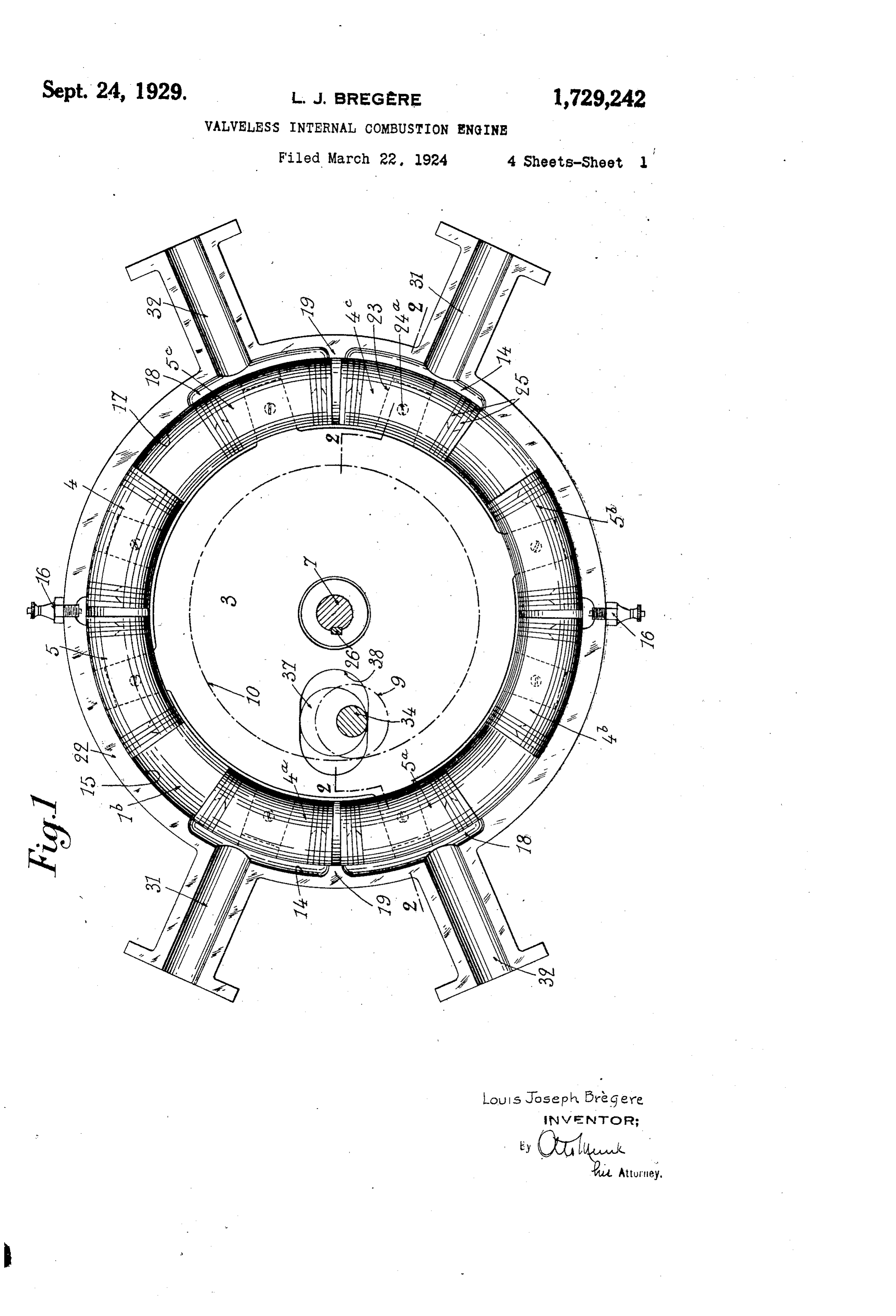
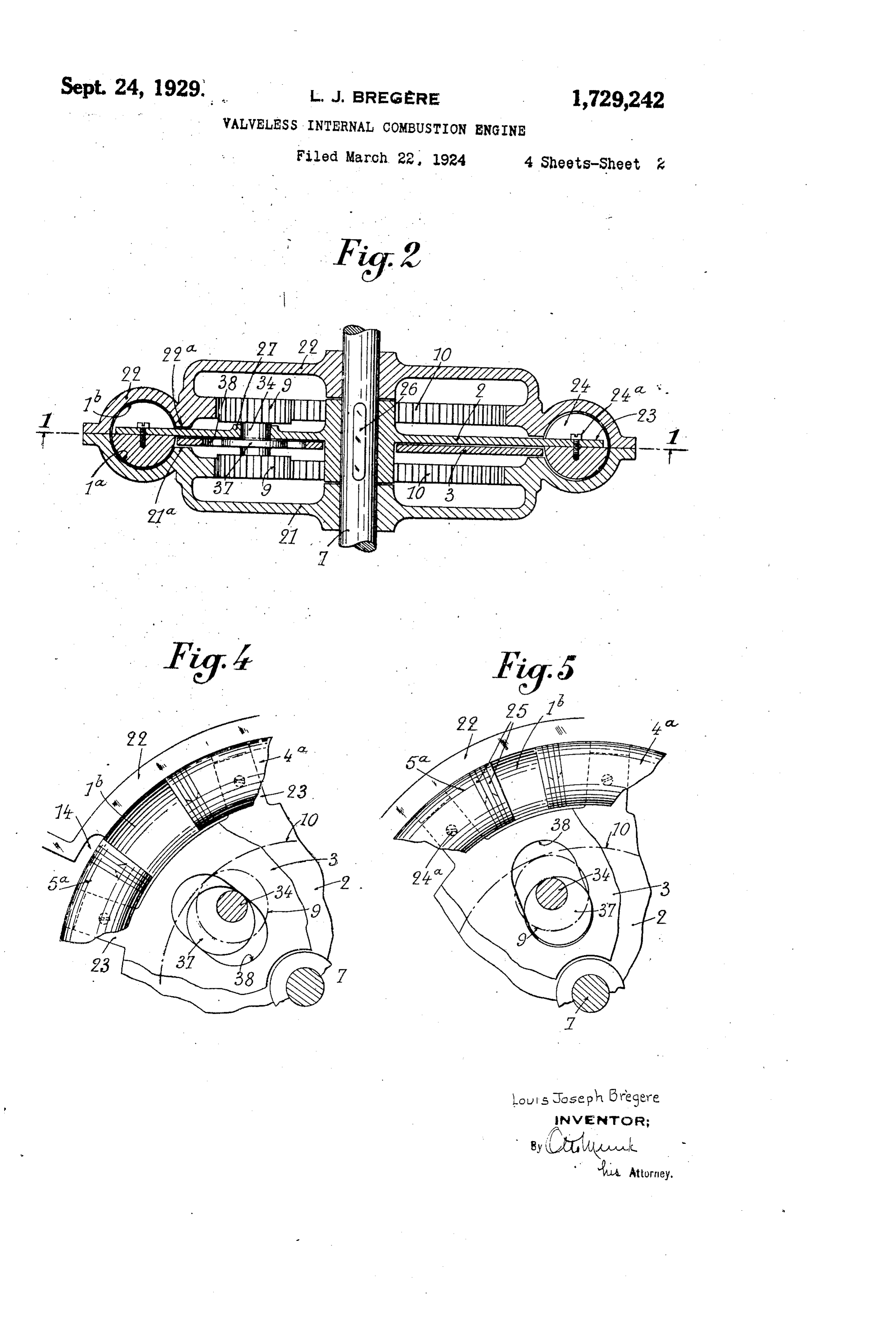
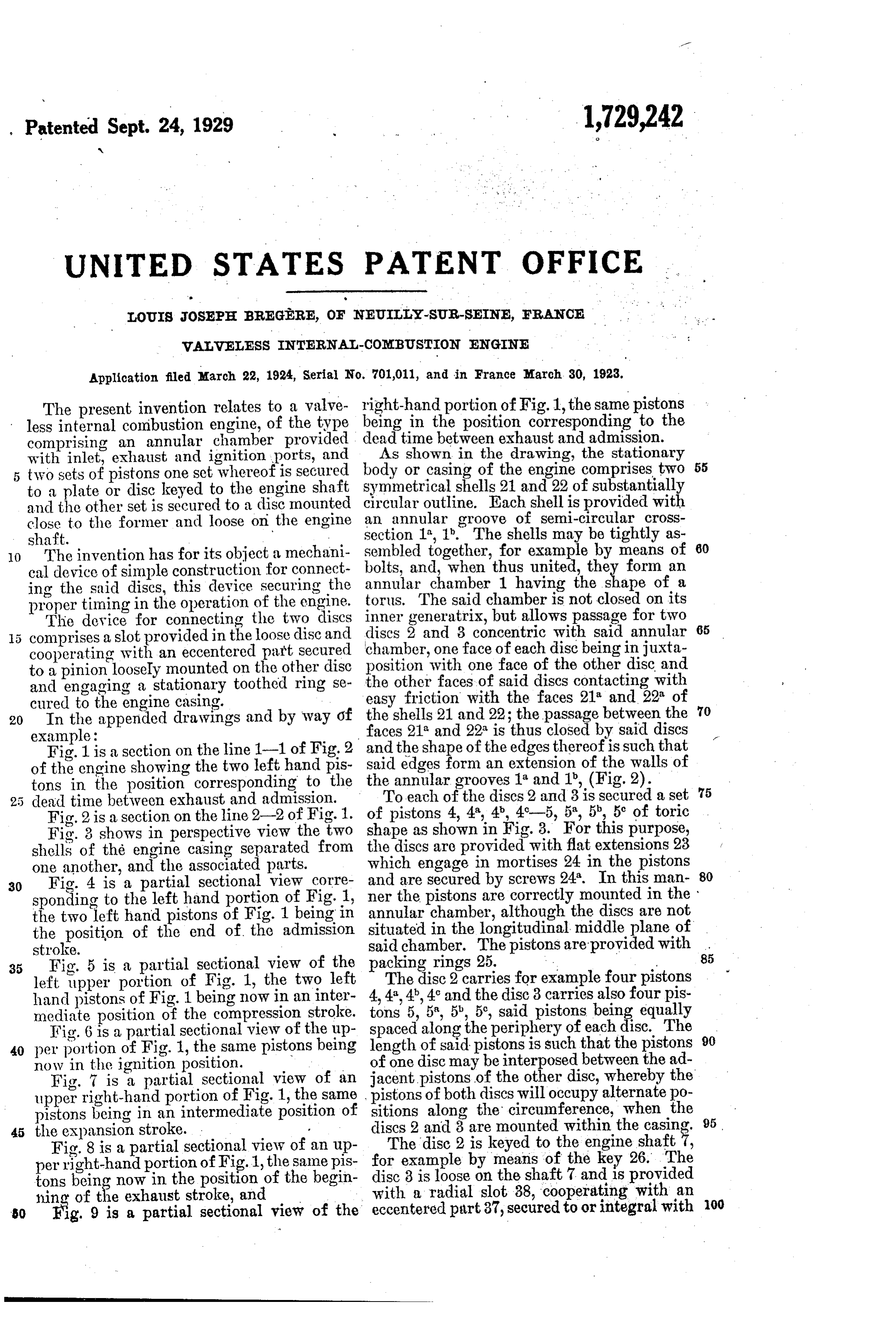
The present invention relates to a valve being less internal combustion engine, of the type in the position corresponding to the comprising an annular chamber provided dead time between exhaust and admission. with inlet, exhaust and ignition ports, and As shown in the drawing, the stationary 55 two sets of pistons one set whereof is secured body or easing of the engine comprises two to a plate or disc keyed to the engine shaft Symmetrical shells 21 and 22 of substantially and the other set is secured to a disc mounted circular outline. Each shell is provided with close to the former and loose on the engine an annular groove of semi-circular cross shaft. Section 1", 1". The shells may be tightly as O The invention has for its object a mechani sembled together, for example by means of 60 cal device of simple construction for connect bolts, and, when thus united, they form an annular chamber 1 having the shape of a ing the said discs, this device securing the torus. The said chamber is not closed on its proper timing in the operation of the engine.
The device for connecting the two discs inner generatrix, but allows passage for two 65 5 comprises a slot provided in the loose disc and discs 2 and 3 concentric with said annular cooperating with an eccentered part Secured chamber, one face of each disc being injuxta position with one face of the other disc and to a pinion loosely mounted on the other disc the other faces of said discs contacting with and engaging a stationary toothed ring Se cured to the engine casing. easy friction with the faces 21 and 22 of 70 20 In the appended drawings and by way of the shells 21 and 22; the passage between the example: faces 21 and 22 is thus closed by said discs Fig. 1 is a section on the line 1-1 of Fig. 2 and the shape of the edges thereof is such that of the engine showing the two left hand pis said edges form an extension of the walls of tons in the position corresponding to the theToannular grooves 1 and 1, (Fig.2). each of the discs 2 and 3 is secured a set 75 5 dead time between exhaust and admission.
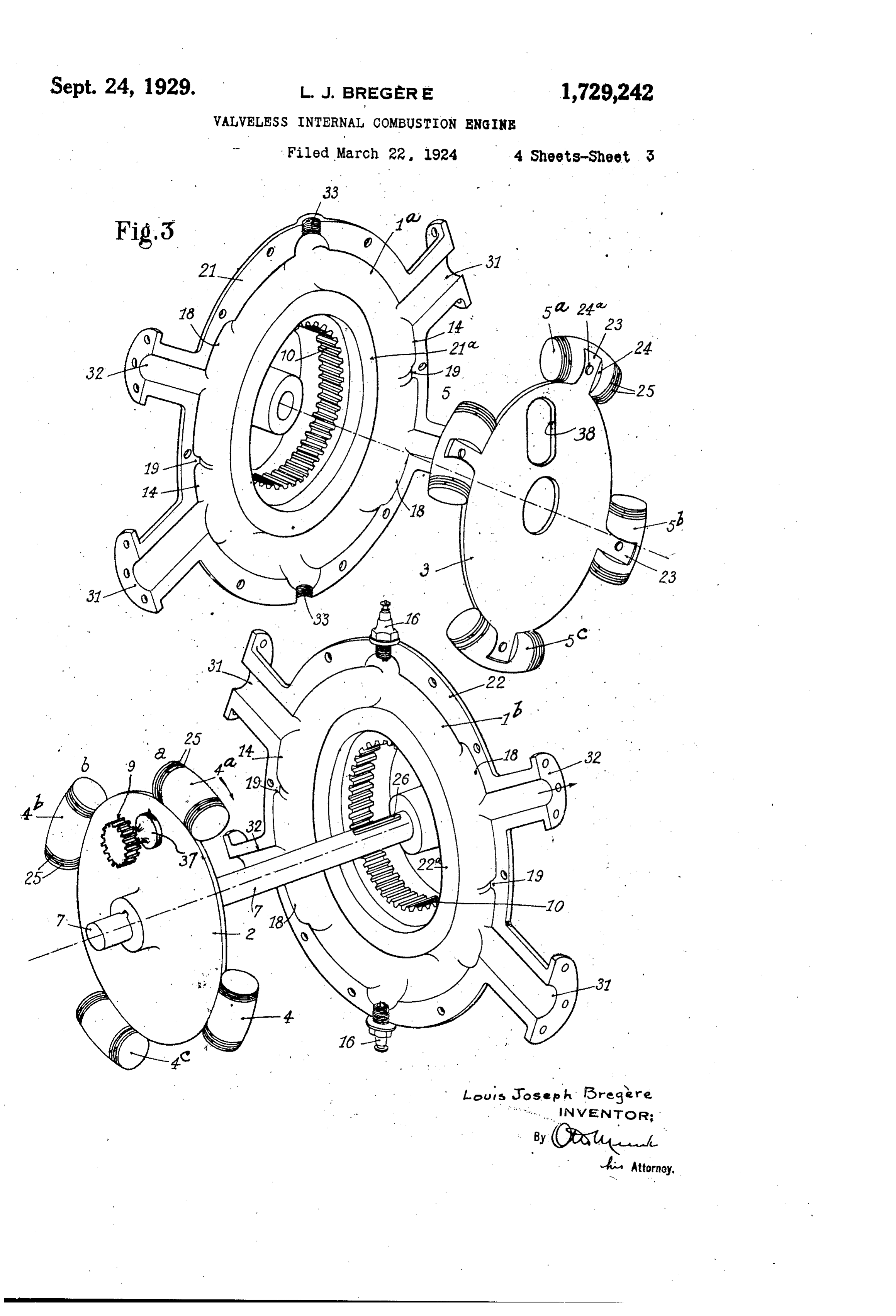
Fig. 2 is a section on the line 2-2 of Fig.1. of pistons 4, 4, 4b, 49-5, 5, 5, 5 of toric Fig. 3 shows in perspective view the two shape as shown in Fig. 3. For this purpose, shells of the engine casing separated from the discs are provided with flat extensions 23 one another, and the associated parts. which engage in mortises 24 in the pistons 80 30 Fig. 4 is a partial sectional view corre ner and are secured by screws 24. In this man sponding to the left hand portion of Fig. 1, the pistons are correctly mounted in the the two left hand pistons of Fig. 1 being in annular chamber, although the discs are not the position of the end of the admission situated in the longitudinal middle plane of said chamber. The pistons are provided with 85
35 Fig. 5 is a partial sectional view of the packing rings 25.
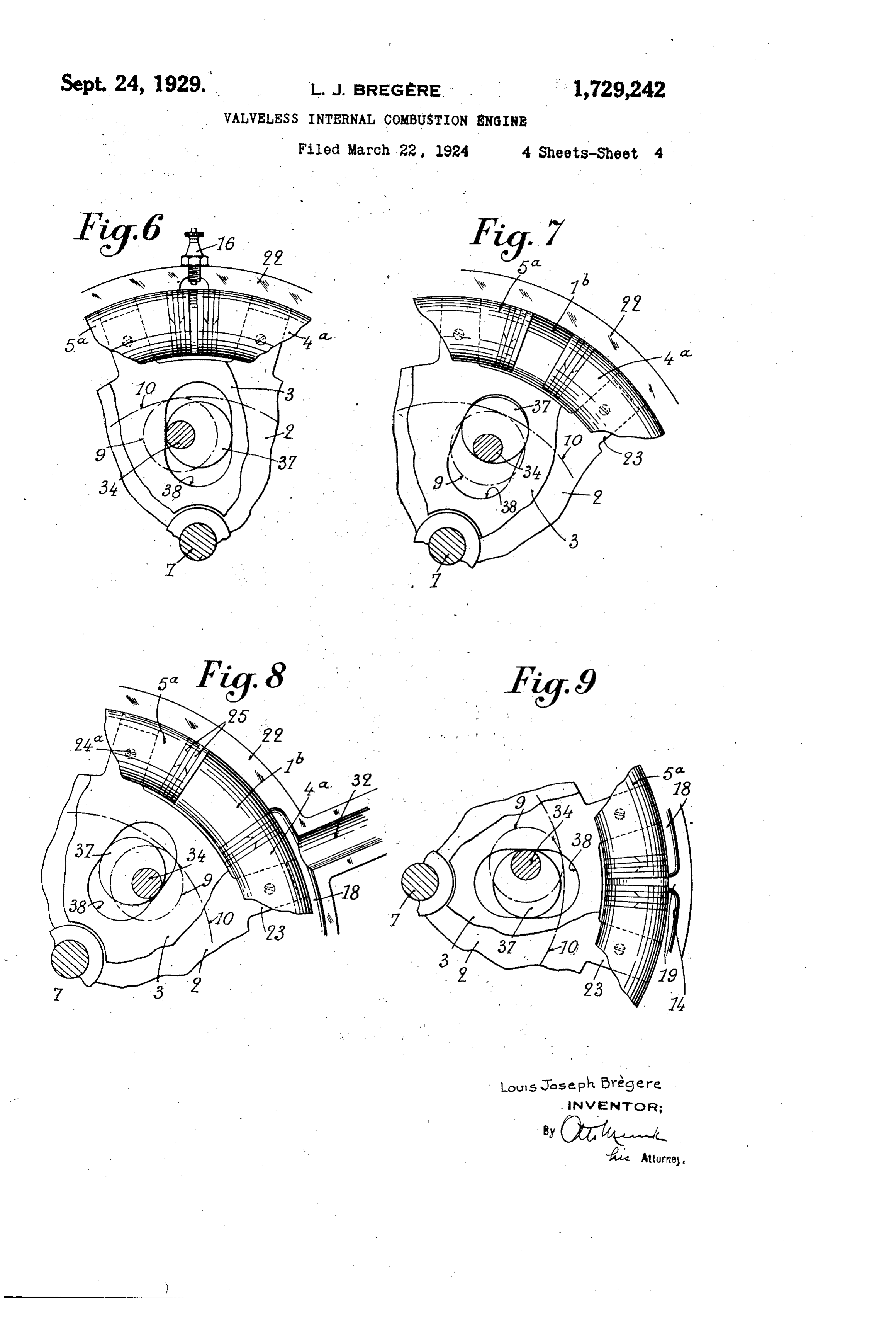
left upper portion of Fig. 1, the two left The disc 2 carries for example four pistons hand pistons of Fig. 1 being now in an inter 4,4', 4', 4' and the disc 3 carries also four pis mediate position of the compression stroke. tons 5, 5", 5", 5, said pistons being equally Fig. 6 is a partial sectional view of the up spaced along the periphery of each disc. The 90 40 per portion of Fig. 1, the same pistons being length of said pistons is such that the pistons now in the ignition position. of one disc may be interposed between the ad Fig. 7 is a partial sectional view of an jacent pistons of the other disc, whereby the upper right-hand portion of Fig. 1, the same pistons of both discs will occupy alternate po sitions2 and pistons being in an intermediate position of discs along3 are themounted circumference, when the within the casing. 95.
Fig. 8 is a partial sectional view of an up The disc 2 is keyed to the engine shaft per right-hand portion of Fig.1, the same pis for example by means of the key 26. The tons being now in the position of the begin disc 3 is loose on the shaft 7 and is provided hisig.of9theis exhaust stroke, and with a radial slot 38, cooperating with an O a partial sectional view of the eccentered part 37, secured to or integral with 00
Page 6
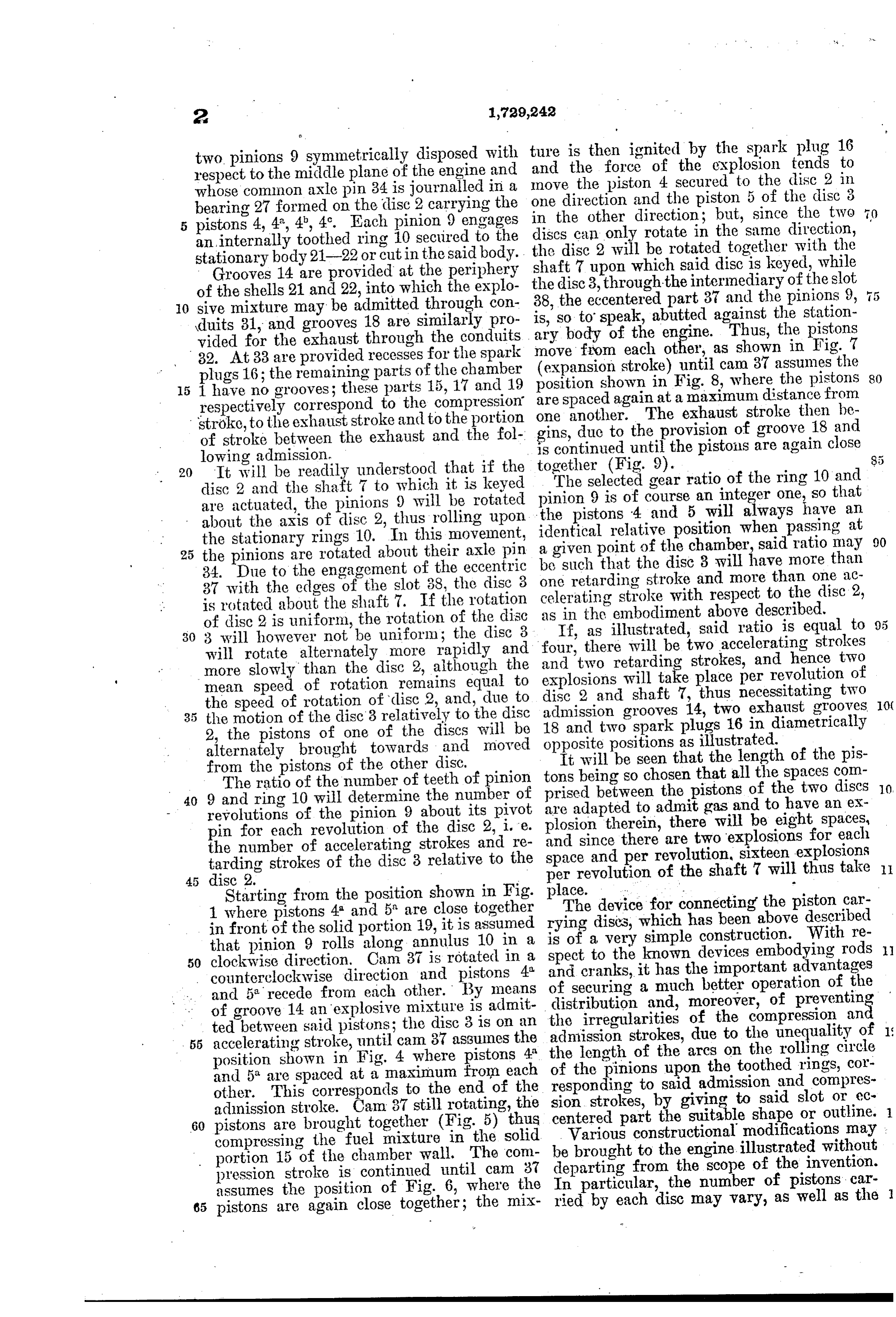
two pinions 9 symmetrically disposed with ture is then ignited by the spark plug 16 respect to the middle plane of the engine and movethe and force of the explosion tends to the piston 4 secured to the disc 2 in whose common axle pin 34 is journalled in a one direction bearing 27 formed on the disc 2 carrying the the other and the piston 5 of the disc 3 5 pistons 4,4', 4', 4'. Each pinion 9 engages in direction; but, since the two an internally toothed ring 10 secured to the discsdisccan only rotate in the same direction, stationary body 21-22 or cut in the said body. the shaft 7 2 will be rotated together with the upon which said disc is keyed, while
Grooves 14 are provided at the periphery the disc 3, through of the shells 21 and 22, into which the explo 38, the eccentered the intermediary of the slot 5 10 sive mixture may be admitted through con is, so to speak, abutted37against part and the pinions 9, duits 31, and grooves 18 are similarly pro ary body of the engine. Thus, the station vided for the exhaust through the conduits move from each other, as shown in pistons the
Fig. 7 32. At 33 are provided recesses for the spark (expansion stroke) until cam 37 assumes the plugs 16; the remaining parts of the chamber 15 1 have no grooves; these parts 15, 17 and 19 positionare spaced shown in Fig. 8, where the pistons 80 again at a maximum distance from respectively correspond to the compression one another.
stroke, to the exhaust stroke and to the portion gins, due to theThe exhaust stroke then be provision of groove 18 and of stroke between the exhaust and the fol is continued until the pistons are again close lowing admission. together (Fig. 9). 20 It will be readily understood that if the The selected gear ratio of the ring 10 and disc 2 and the shaft 7 to which it is keyed pinion 9 is of course an integer one, so that are actuated, the pinions 9 will be rotated the pistons 4 and 5 will always have an about the axis of disc 2, thus rolling upon identical relative position when passing at 90 the stationary rings 10. In this movement, 25 the pinions are rotated about their axle pin a given point of the chamber, said ratio may 34. Due to the engagement of the eccentric be one such that the disc 3 will have more than retarding stroke and more than one ac 37 with the edges of the slot 38, the disc 3 is rotated about the shaft 7. If the rotation celerating as in the stroke with respect to the disc 2, embodiment above described.
of disc 2 is uniform, the rotation of the disc If, as illustrated, said ratio is equal to 30 3 will however not be uniform; the disc 3 four, there will be will rotate alternately more rapidly and and two retarding strokes, and hencetwo accelerating strokes more slowly than the disc 2, although the explosions will take place per revolutiontwo of mean speed of rotation remains equal to disc 2 and shaft 7, thus necessitating two the speed of rotation of disc 2, and, due to 5 the motion of the disc 3 relatively to the disc admission 18 and two grooves 14, two exhaust grooves 10C spark plugs 16 in diametrically 2, the pistons of one of the discs will be opposite positions as illustrated. alternately brought towards and moved It will be seen that the length of the pis from the pistons of the other disc.
The ratio of the number of teeth of pinion prised between the pistonsallofthethespaces
40 9 and ring 10 will determine the number of are adapted to admit gas and to have andiscs two
revolutions of the pinion 9 about its pivot plosion therein, there will be eight spaces, pin for each revolution of the disc 2, i.e. and since there are two explosions for each the number of accelerating strokes and re space and per revolution, sixteen explosions tarding strokes of the disc 3 relative to the per revolution of the shaft 7 will thus take discStarting 2. from the position shown in Fig. place. -- 1 where pistons 4 and 5 are close together rying The device for connecting the piston car in front of the solid portion 19, it is assumed is of adiscs, which has been above described that pinion 9 rolls along annulus 10 in a spect tovery the simple construction. With re known devices embodying rods 50 clockwise direction, Cam 37 is rotated in a counterclockwise direction and pistons 4 and cranks, it has the important advantages and 5 recede from each other. By means of securing a much better operation of the distribution and, moreover, of preventing of groove 14 an explosive mixture is admit the irregularities of the compression an ted between said pistons; the disc 3 is on an admission strokes, due to the unequality of 55 accelerating stroke, until cam 37 assumes the position shown in Fig. 4 where pistons 4 the length of the arcs on the rolling circle and 5° are spaced at a maximum from each of the pinions upon the toothed rings, cor responding to said admission and compres other. This corresponds to the end of the sion strokes, by giving to said slot or ec admission stroke. Cam 37 still rotating, the 60 pistons are brought together (Fig. 5) thus centered part the suitable shape or outline. compressing the fuel mixture in the solid be broughtconstructional
to the engine illustrated without portion 15 of the chamber wall. The com departing from the scope of the invention. pression stroke is continued until cam 37 assumes the position of Fig. 6, where the In particular, the number of pistons, car 65 pistons are again close together; the mix ried by each disc may vary, as well as the
Page 7
ratio between the number of teeth on the pinions 9 and on the rings 10. The varia tion of this ratio allows of obtaining, for constant linear speeds of the piston, oper 5 ating speeds for the driving shaft which are variable according to said ratio. The mount ing of the pistons on the discs may be as desired. The periods of admission, compres sion, explosion and exhaust may be arranged 10 for different cycles; furthermore the principle of operation of this engine may be applied to compressors, pumps, etc., the main shaft being in such case driven by an engine or by any power transmission device.
15 Having now described my invention what I claim as new and desire to secure by Let ters Patent is:
s". An internal combustion engine comprising a body, a shaft rotatably supported by said 20 body, toothed rings secured to said body . and concentric with said shaft, an annular chamber within said body, inlet and exhaust ports in said chamber, two sets of pistons adapted to move within said chamber, and 25 respectively carried by two adjacent discs disposed on either side of the longitudinal middle plane of said chamber, one first disc being rigidly mounted on said shaft and the other disc being mounted loose on the same, 30 the pistons of one set alternating with the pistons of the other set, pinions rotatably mounted in said first disc and respectively adapted to engage said toothed rings, an ec centered part secured to one pinion and a slot 35 in said loose disc and cooperating with said eccentered part, whereby a reciprocating mo tion is imparted to the loose disc with respect to the other.
In testimony whereof I have signed my 40 name to this specification.
LOUIS JOSEPH BREGERE.
Provenance
- Collection
- Cited prior art
- Original PDF
- patentimages.storage.googleapis.com →
- Filed
- 1924-03-22
- Pages
- 7
- Method
- pdftotext (the PDF's own text layer) + pdftoppm 300dpi page scans
- Source
- Google Patents bibliographic record
- Granted
- 1929-09-24
- Inventors
- Bregere Louis Joseph
- Transcribed from
- patentimages.storage.googleapis.com →