patent · US1969839
Apparatus for absorbing solar energy
14 August 1934
Page 1
a APPARATUS. FOR ABSORBING SOLAR ENERGY . _ :
NANARANANAS
PLD fof lf erbhefr — 0 ; .
LLL SESS Froge7d JL. Govarve MY, GG hy YZ ify
SEZ.
Wiles 70
WD raheok :
Page 2
Patented Aug. 14, 1934
UNTER: STATES
PATENT OFFICE
: - APPARATUS FOR ABSORBING SOLAR —
Robert H. Goddard, Worcester, Mass.
Application October 30, 1930, Serial No. 492,267
_ 17 Claims,
_ This invention relates to apparatus by “which solar energy may be effectively. utilized” in the heating of water, the production of steam or the raising of any fluid to a higher temperature. ~
It is the general, object of my. ‘invention to provide apparatus for such purposes so designed that a relatively large heating action may ‘pe attained by use of a relatively small apparatus. ©
A further object of my invéntion is to provide apparatus which is simple in construction,..reliable and efficient in operation and ‘which. involves the use of no moving parts..
My improved apparatus produces: rapid. and complete vaporization of a liquid at high temperatures, with a minimum loss of heat during
_ the vaporizing operation.
My invention. further relates. to arrangements and combinations of parts which will be hereinafter described and more particularly pointed out in: the appended claims.
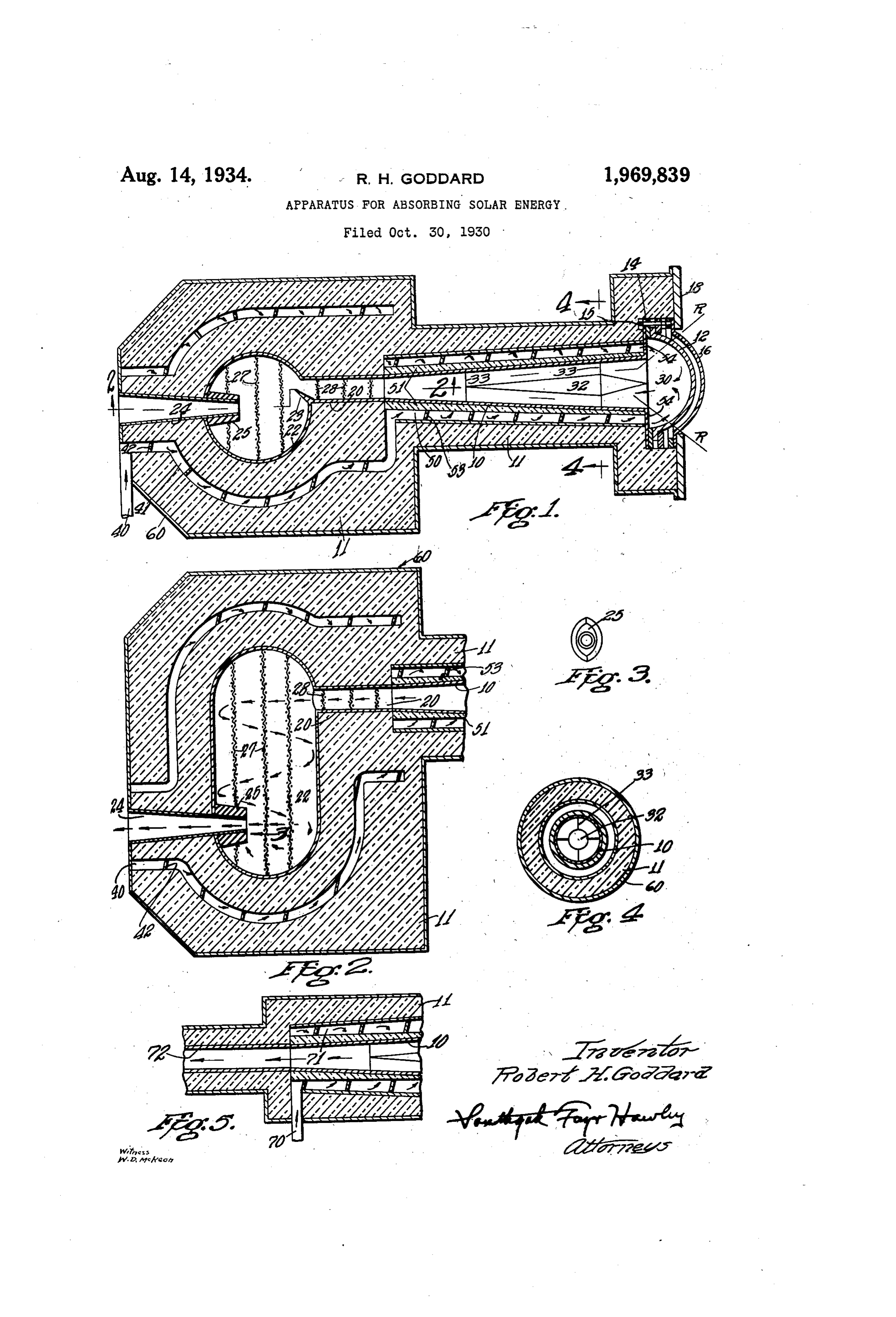
A preferred form of the jnvention is shown in the drawing, in which
Fig. 1 is a longitudinal sectional. view of my improved apparatus;
Fig. 2 is a partial sectional view, taken ‘along the line 2—2 in Fig. 1;_
Fig. 3 is an end view of a ‘detail part, looking in the direction of the arrow 3. in Fig. 2; .
Fig. 4 is a sectional elevation, taken | along the line. 4—4 in Fig. 1; and
Fig. 5 is a fragmentary sectional ‘view of & modified structure.
Referring to the’ drawing, my. “improved. heating apparatus comprises a relatively. long and preferably conical tube 10, suitably supported in a casing 11 of insulating material: The-length ‘of the. tube 10 should. be ‘substantially greater than twice its longest diameter. A substantially hemispherical window 12: of ‘quartz or very transparent glass is mounted at the large end of the ‘conical tube 10 and-is held in-position by clamping rings 14.and bolts 15. When. the apparatus us exposed to strong winds, a second. and outer similar window 16. is preferably mounted in spaced relation: to the window 12, .A. refractory ‘disc 18 may be. secured to the front of the .apparatus, protecting the. edge portions. of ‘the. windows from excessive heat.
The conical tube-10 is connected ‘at iter rear: end
through a-passage 20 to a mixing. and drying - chamber 22 which. is. preferably. of substantially ©
cylindrical form. A barrier 23. at: the-rear end
of the passage 20-restricts:the outlet of the pas--
sage fromthe chamber 22 and. causes the vapor
‘imember, 32 may be. of - hollow metal construc-
to flow in a substantially tangential direction as it enters the chamber 22,
A discharge passage 24 projects in ‘through the side of the chamber which is opposite to the passage 20 and provides for the discharge of 60 highly heated vapor from the mixing and drying chamber.
_ .The projecting innerend of the discharge passagé is preferably coated or built up to a sub-
‘stantially streamlike section, as indicated at 25 65.
in Fig. 3, thus reducing the interference with the rapid circulation of the liquid and vapor within the mixing chamber.
Fine mesh metal screens 27 are preferably provided in-the chamber 22 to effect the breaking 70 up and complete vaporization of any liquid entrained in the vapor entering the mixing chamber. Similar screens 28 may be provided in the passage 20 for a similar purpose. ;
‘The discharge passage 24 is preferably in the form. of an outwardly enlarged conical nozzle through which the highly heated vapors are discharged for heating or other desired purposes.
The conical tube 10 is preferably formed of relatively thin metal and is highly polished on its inner surface. The window 12 encloses a substantial fluid-circulating space 30 in front of the large end of the conical tube 10.
Assuming that this space and the interior of the tube.10 have been supplied with water or other fiuid in a manner to be described, the action of this part of the apparatus, when exposed to the heat of the sun,.is as follows:—
“Ultra violet or heat rays R traverse the fluid- ‘circulating space. 30 and are concentrated at a 99 point inside. of the large end of the conical tube ~ 10... These heat rays traverse the liquid in the tube 10 and are repeatedly reflected back and forth by the polished internal conical ‘surface of the tube, which, however, is. of such..slight ‘inclination that. ‘the rays are not to any substantial extent reflected. back into the space 30.
The heat of the rays R is thus rapidly absorbed by the.liquid'in the space 30 and tube 10, raising the temperature ‘thereof and causing vapor to be formed, which vapor is ‘discharged rearward through the. passage: 20 to the mixing chamber 22 in: which the vaporization ” is completed, the dry ‘vapor. being discharged through ‘the nozzle
“The ‘action within: the tube 10 may be facili-
‘tated: ‘by: nounting a spreading member 32- there-
in:‘said'member 32 being centrally located ‘in the tube 10 by guy wires 33, (Figs. 1 and 4). The
Page 3
tion and is preferably formed with two abutting conical portions, as clearly shown in Fig. 1.
In order to still further conserve heat, I feed the liquid to.be vaporized through an inlet pipe 40 to a space or passage 41 formed in the insulating material of the casing 11 but substantially spaced both from the chamber 22 and its con~ necting passages: and also from the outer wall of the apparatus. ‘This space or passage 41 is provided with spirally arranged partitions. 42 which cause the entering liquid to traverse a heli-
cal path and to repeatedly encircle the nozzle:
24, the chamber 22 and the connecting passage
the details herein disclosed, otherwise than as set forth in the claims, but what I claim is: —
1. Apparatus for absorbing solar energy comprising a conical tube having an internal refiecting surface, a transparent window through which solar heat rays are admitted to the larger end of said tube, a conduit through which a heat-absorbing fluid is. delivered to said ‘tube: through its larger open end, and means to conduct heated fluid from the smaller end of said tube, said
transparent window being substantially. semi-
spherical and inclosing a fluid-circulating space
Of substantial volume in front of said conical
The liquid then enters a space or passage 50.
which surrounds the conical tube 10 but is’‘spaced-
therefrom by a portion of insulating material, 51 which is of increased thickness toward the small
end of the tube where. the temperatures:- are-
higher.. -
* The passage 50°is “also provided: with spiral partitions 53 forming a second ‘helical path through. which the: liquid ‘is conducted’ to the front end of the tube 10° where it is discharged in a tangential direction through openings 54 into. the ‘circulating ~space °30' previously, described,
The outside of the apparatus is preferably provided ‘with'a metal casing 60,. impervious to air and particularly designed to protect the more or less porous insulating material from the action of wind.
Experiments with the apparatus indicate that
_ its high efficiency is due in part to the fact that
vaporization of the liquid ‘takes place throughout the entire body of the liquid in the conical tube "10 and is not confined to those portions of liquid in contact with the tube itself, which, due to its reflecting surface, does not absorb an appreciable amount of heat.
The liquid ‘traversing the passages 41° and 50 enclosing the inner heating portions ‘of ‘the apparatus serves to absorb. such heat as'may escape through the insulating material of ‘the ‘walls, but it is still -at relatively low temperature when it enters the circulating space 30 and ‘thus serves to prevent the window 42 from becoming over
heated.
It will also be noted that as the liquid enters the conical tube 10; the cooler portions of the liquid tend to move to the outside of the cone’ in contact with the reflecting metal, so that heat losses through the tube 10 are reduced and the temperature of the tube 10 ordinarily remains below that of the liquid and vapor flowing therethrough: The: provision of the inner ‘conical
‘member 32 makes the action of the apparatus
more definite ‘and rapid.
‘It- may be noted that the- ultra-violet rays tr: ansmitted by the window 12 when quartz is used are highly concentrated in the: tube’ 10 and have a, strong sterilizing action which is’ of great importance under certain circumstances.
In cases where it is not’ essential that ‘the
‘liquid be completely. vaporized, as where the liq-
uid is to be used for heating only, the mixing
chamber. and nozzle may. be" dispensed . with, as
shown in Fig. 5, in which case the liquid enters directly through a pipe 70 to a helical passage
‘V1. surrounding | the conical tube 10. In this con-. struction, the vapor : formed in the tube.10 may be discharged . directly through an_ outlet Pas-
sage 72,
“Having thus described: my- ‘invention and: the.
advantages thereof, I do not wish to be limited to ;
tube.
2, Heat-absorbing apparatus as set forth in claim ‘1,-in-which the conduit opens directly and freely into said fluid-circulating space.
3. Heat-absorbing apparatus as set forth in ‘claim: 1, ‘in which the conduit is mounted and connected to deliver the heat-absorbing fluid directly into said fluid-circulating ‘space in a tangential direction.’
“4, Apparatus for ‘absorbing solar energy’ ‘comprising a conical tube having an internal refiecting surface, a transparent window through which solar heat ‘rays are admitted to the larger . end of ‘said tube; a conduit’ through which a heatabsorbing fluid is delivered to said tube. through its larger open’ end, and means ‘to conduct heated fluid from’ the smaller end ‘of said tube, said transparent window consisting of two concentric
semi-spherical portions mounted in spaced: rela~
tion to each other.
5. Apparatus for ‘absorbing solar energy comprising a conical tube having an internal’ reflecting surface, a transparent window through which solar heat.rays are admitted to the larger end of said tube, a conduit through which a’ heat-absorbing ftuid is delivered to said tube through its larger open end, and means to conduct heated fluid from the smaller end of’ said ‘tube; said means for conducting away heated fluid ineluding a mixing and drying chamber.
6. Heat-absorbing apparatus as set forth’ in claim 5, in which an ‘outwardly-enlarged conical discharge nozzle is included; having its inner end open to said: chamber and ‘Said: nozzle’ extending outwardly: therefrom.
7, Heat-absorbing apparatus as set forth in claim 5, in which an outwardly-enlarged ‘conical ‘discharge nozzle is ‘included, said nozzle having its inner end projecting into said mixing and drying chamber and said-inner end having: a stream- Tine external surface.
8. Heat- -absorbing apparatus: as ‘set. forth’ in }
claim 5, in which'a‘plurality of fine wire screens are mounted in said chamber and effect’ the break-
- ing-up ‘and more ‘complete vaporization of liquid
entrained in the heated vapor: which enters said chamber. .
9. Heat-absorbing apparatus: as® set: forth: ‘in claim 5;-in which the mixing and drying chamber is of substantially cylindrical- cross section and is provided- with a discharge outlet and with an inlet connection from said conical - ‘tube; said inlet connection: being so-disposed: that: ‘vapor ‘enters said chamber from said connection. in’ B- ‘Substantially tangential. direction.
10: Apparatus for absorbing solar. energy comprising a conical tube having an: internal refiect- ‘ing ‘surface,:a transparent window.through which solar heat. rays:are admitted to the larger -end: of Said tube; a conduit through which:a heat-absorb-
“ing. fluid is delivered: to: said. tube: through. its
larger open end, and means to conduct heated
Page 4
fluid from the smaller end of said tube, said means for conducting away heated fluid including a mixing and drying chamber and a discharge nozzle, a thick heat-insulating covering for the external surfaces of said apparatus, and an outer casing for said apparatus and insulating covering, which is substantially impervious to air.
11. Apparatus for absorbing solar energy comprising a conical tube having an internal reflecting surface, a transparent window through which solar heat rays are admitted to the larger end of said tube, a conduit through which a heat-absorbing fluid is delivered to said tube through. its Jarger open end, means to conduct heated fluid from the smaller end of said tube, said means for conducting away heated fluid including a mixing and drying chamber and a. discharge nozzle, a thick heat-insulating covering for the external surfaces of said apparatus, said apparatus having a fluid inlet passage therefor, positioned between the inner and outer surfaces of said insulating covering and substantially spaced from said surfaces.
12. Heat-absorbing apparatus as set forth in claim 11, in which said fluid inlet passage provides a helical path for the fluid.
13. Apparatus for absorbing solar energy comprising a conical tube having an internal reflecting surface, a transparent window through which solar heat rays are admitted to the larger end of said tube, a conduit through which a heat-absorbing fluid is delivered to said tube through its Jarger open end, and means to conduct heated fluid from the smaller end of said tube, said means for conducting away heated fluid including a mixing and drying chamber, and inlet and outlet connections to said chamber, which connections are positioned substantially out of alignment with each other.
14, Apparatus for absorbing solar energy com-
prising a conical tube having an internal reflecting surface, a transparent window through which solar heat rays are admitted to the larger end of said tube, a conduit through which a heat-absorbing fluid is delivered to said tube through its larger open-end, means to conduct heated fluid from the smaller end of said tube, and a directing member mounted within said conical tube and spaced from the internal conical wall thereof, said member directing fluid entering said tube outwardly toward said internal conical wall.
15. Apparatus for absorbing solar energy comprising a conical tube having an internal reflecting surface, a transparent window through which solar heat rays are admitted to the larger end of said tube, a conduit through which a heat-absorbing fluid is delivered to said tube through its larger open end, means to conduct heated fluid from the smaller end of said tube, and a reversely tapered tubular conical member axially centered in spaced relation to the internal surface of said conical tube and outwardly deflecting fluid entering said tube.
16. Heat-absorbing apparatus comprising a heating tube, means to direct solar heat rays into said tube, a mixing chamber, means to conduct
heated vapor from said tube to said chamber, |
means to conduct vapor from said chamber, and means to direct said vapor to enter said mixing chamber in a substantially tangential direction. 17. Heat-absorbing apparatus comprising a heating tube, means to direct solar heat rays into said tube, a mixing chamber, passages encircling said mixing chamber and heating tube, means to conduct heated vapor from said tube to said chamber, means to conduct vapor from said chamber, and means to feed a fluid to be heated to said heating. tube, said fluid traversing said encircling passages before entering said tube.
; ROBERT H. GODDARD.
Provenance
- Collection
- Cited prior art
- Original PDF
- patentimages.storage.googleapis.com →
- Filed
- 1930-10-30
- Pages
- 4
- Method
- pdftoppm 300dpi + tesseract 5 (eng)
- Source
- Google Patents bibliographic record
- Granted
- 1934-08-14
- Inventors
- Robert H Goddard
- Transcribed from
- patentimages.storage.googleapis.com →