patent · US4878540
Apparatus and process for pumping fluid from subterranean formations
7 November 1989
Page 1 — bibliographic record
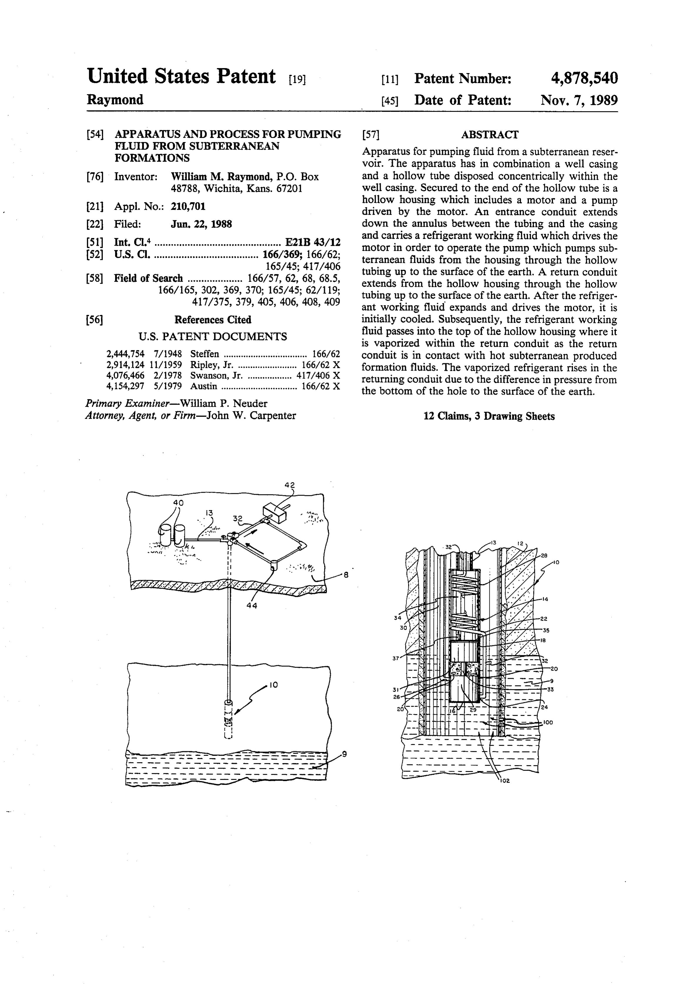
United States Patent (19) 11 Patent Number: 4,878,540 Raymond (45) Date of Patent: Nov. 7, 1989 (54) APPARATUS AND PROCESS FOR PUM.PNG 57 ABSTRACT
FLUID FROMSUBTERRANEAN
FORMATIONS Apparatus for pumping fluid from a subterranean reser voir. The apparatus has in combination a well casing (76) Inventor: William M. Raymond, P.O. Box and a hollow tube disposed concentrically within the 48788, Wichita, Kans. 67201 well casing. Secured to the end of the hollow tube is a 21 Appl. No.: 210,701 hollow housing which includes a motor and a pump driven by the motor. An entrance conduit extends 22 Filed: Jun. 22, 1988 down the annulus between the tubing and the casing (51) Int. Cl." .............................................. E21B 43/12 and carries a refrigerant working fluid which drives the (52) U.S. C. ...................................... 166/369; 166/62; motor in order to operate the pump which pumps sub 165/45; 417/406 terranean fluids from the housing through the hollow (58) Field of Search .................... 166/57, 62, 68, 68.5, tubing up to the surface of the earth. A return conduit 166/165, 302,369, 370; 165/45; 62/119; extends from the hollow housing through the hollow 417/375, 379, 405, 406, 408, 409 tubing up to the surface of the earth. After the refriger ant working fluid expands and drives the motor, it is 56 References Cited initially cooled. Subsequently, the refrigerant working
is vaporized within the return conduit as the return 2,444,754 7/1948 Steffen .................................. 166/62 conduit is in contact with hot subterranean produced 2,914,124 11/1959 Ripley, Jr. ..... 166/62 X formation fluids. The vaporized refrigerant rises in the 4,076,466 2/1978 Swanson, Jr. . 417/406 X returning conduit due to the difference in pressure from 4,154,297 5/1979 Austin ............................... 166/62 X the bottom of the hole to the surface of the earth. Primary Examiner-William P. Neuder
Attorney, Agent, or Firm-John W. Carpenter 12 Claims, 3 Drawing Sheets
Page 2
Drawing sheet — no readable text.
Page 3
Drawing sheet — no readable text.
Page 4
Drawing sheet — no readable text.
Page 5
surface and the warmer temperature of the fluids in the
APPARATUS AND PROCESS FOR PUM.PNG reservoir.
FLUID FROMSUBTERRANEAN FORMATIONS It is another object of the present invention to pro vide a well pumping system wherein a condenser is
FIELD OF THE INVENTION located at the surface of the earth with sufficient capac This invention relates to an apparatus and process for ity,vert including mechanical chilling, if necessary, to con a fluorocarbon vapor to a fluid.
pumping oil, water, or any other subterranean fluid, It is yet another object of the present invention to from wells drilled into reservoirs beneath the surface of provide a well pumping system wherein a vaporizer is the earth. More specifically, this invention relates to an 10 located apparatus and process for pumping subterranean fluids at the bottom of the well with sufficient capac from wells drilled into subterranean formations beneath ity to cause the fluorocarbon liquid to boil off to a va the surface of the earth, which utilizes the elevation por.It is still yet another object of the present invention to difference between the earth's surface and that of the provide a well pumping system wherein a pump may be reservoir, along with the temperature difference be 15 used, if necessary, to inject the fluorocarbon fluid down tween the ambient air at the earth's surface and the warmer temperature of the subterranean fluids from the liquid state into the its conduit well bore to insure its maintaining a the bottom of the hole.
subterranean formation. The foregoing objects are accomplished by the prac DESCRIPTION OF THE PRIOR ART tice of the present invention. Broadly, the present in One of the current problems of the oil producing 20 system vention accomplishes its desired objects by providing a industry is the high cost of fuel for pumping oil from earth's surface that utilizes the elevation difference between the wells. There are hundreds of thousands of "stripper' oil temperature difference and that of the reservoir, along with the wells in this country which operate at a small margin of between the ambient air at the profit. The main expense for pumping most of these 25 inearth's surface and the warmer temperature of the fluids the reservoir. The system utilizes a heat rejection wells is fuel. The recent decline in the world price for apparatus such as a condenser located at the earth's oil has rendered many of these wells unprofitable. With surface which out a more efficient, less fuel costly means of pumping, located at the isbottom cooled by the ambient air. A vaporizer, of the hole, supplies heat to the they will be plugged and abandoned, resulting in the system utilizing the warmth of the fluid coming from loss of their recoverable reserves. It has been discov 30 the subsurface reservoir. A liquid ered that temperature and elevation differences that such as freon, flows from the surfacefluorocarbon fluid, condenser down a exist in most deep wells could be utilized to create conduit to the bottom of an oil well at relatively high power to pump the wells, eliminating all or most of the pressure where it drives a hydraulic motor which is fuel required with present pumping methods. connected to a pump by a shaft. The pump receives oil A patentability investigation was conducted on meth 35 from the subsurface oil reservoir. The hydraulic motor ods that employ temperature and elevation differences drives the pump which sends the oil to the surface. The in transporting fluids, and the following patents were fluorocarbon fluid passes from the motor into a con discovered: U.S. Pat. No. 4,187,686 to Pommier; U.S. denser which has heat supplied to it by the fluid being Pat. No. 4,232,524 to Goyat; U.S. Pat. No. 3,953,971 to produced from the subsurface reservoir. The fluorocar Parker; U.S. Pat. Nos. 4,342,197 and 3,898,020, both to bon fluid absorbs heat in the vaporizer and boils off to a Matthews; and U.S. Pat. No. 4,328,673, also to Mat vapor. The vapor then returns through a conduit to the thews. The majority of the systems disclosed in those condenser at the surface. The condenser cools the va prior art references comprise a geothermal energy re por, condensing it to a liquid, so that the process is covery apparatus making use of thermal energy stored started all over again. In some cases with the present by subterranean heat sources in hot, solute-bearing well 45 invention, it may be desirable to extract heat from the water to generate vapor or superheated fluid from a vapor by the use of a chilling device to assist its return surface-injected flow of a clean working liquid; heated to a liquid state at the surface of the earth. In other fluid is then used to operate a turbine-driven pump cases, it may be desirable to add pressure to the liquid within the well for pumping the hot brine at high pres by means of a pump at the surface to be sure of its main sure and always in liquid state to the earth's surface, 50 taining a liquid state as it flows to the bottom of the where it transfers its heat in a binary, closed-loop, heat hole. Another aspect of this invention is to take advan exchanger turbine-alternator combination for genera tage of the difference in hydrostatic pressure created by tion of electrical power. Residual brine is pumped back the various fluids in its system. Liquid fluorocarbon is into the earth, while the clean, cooled working liquid is heavier than either the oil or water that is to be pro condensed at the surface-located system and is returned 55 duced from the subsurface reservoir. It therefore cre continuously to the deep well pumping system for gen ates a greater hydrostatic pressure at the bottom of the erating working vapor. None of the foregoing prior art hole furnishing a work advantage.
patents teach or suggest the particular apparatus and These, together with various ancillary objects and method of this invention. features which will become apparent to those skilled in SUMMARY OF THE INVENTION the art as the following description proceeds, are at tained by this novel apparatus and process for pumping
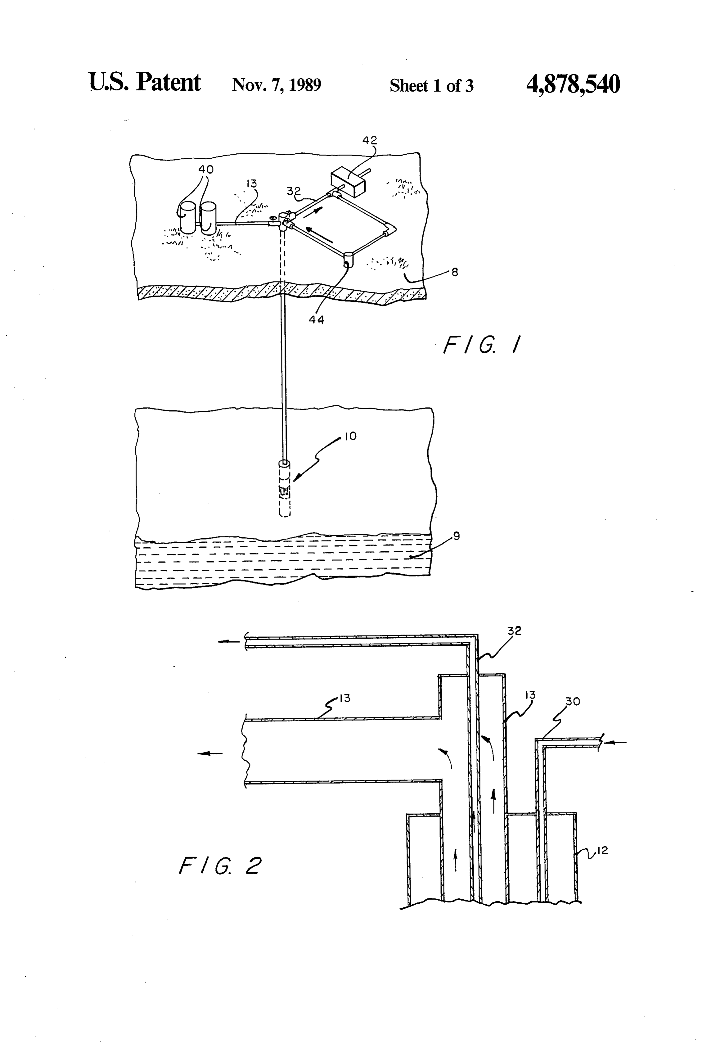
It is therefore an object of the present invention to fluid from subterranean formations, a preferred embodi provide an improved, more economical system for ment being shown with reference to the accompanying pumping fluids such as oil, water, or a combination drawings, by way of example only, wherein: thereof, from reservoirs in the subsurface of the earth, 65 utilizing the elevation difference between the earth's DESCRIPTION OF THE DRAWINGS surface and that of the reservoir, along with the temper FIG. 1 is a perspective view of the present invention ature difference between the ambient air at the earth's showing the relationship of the various components on
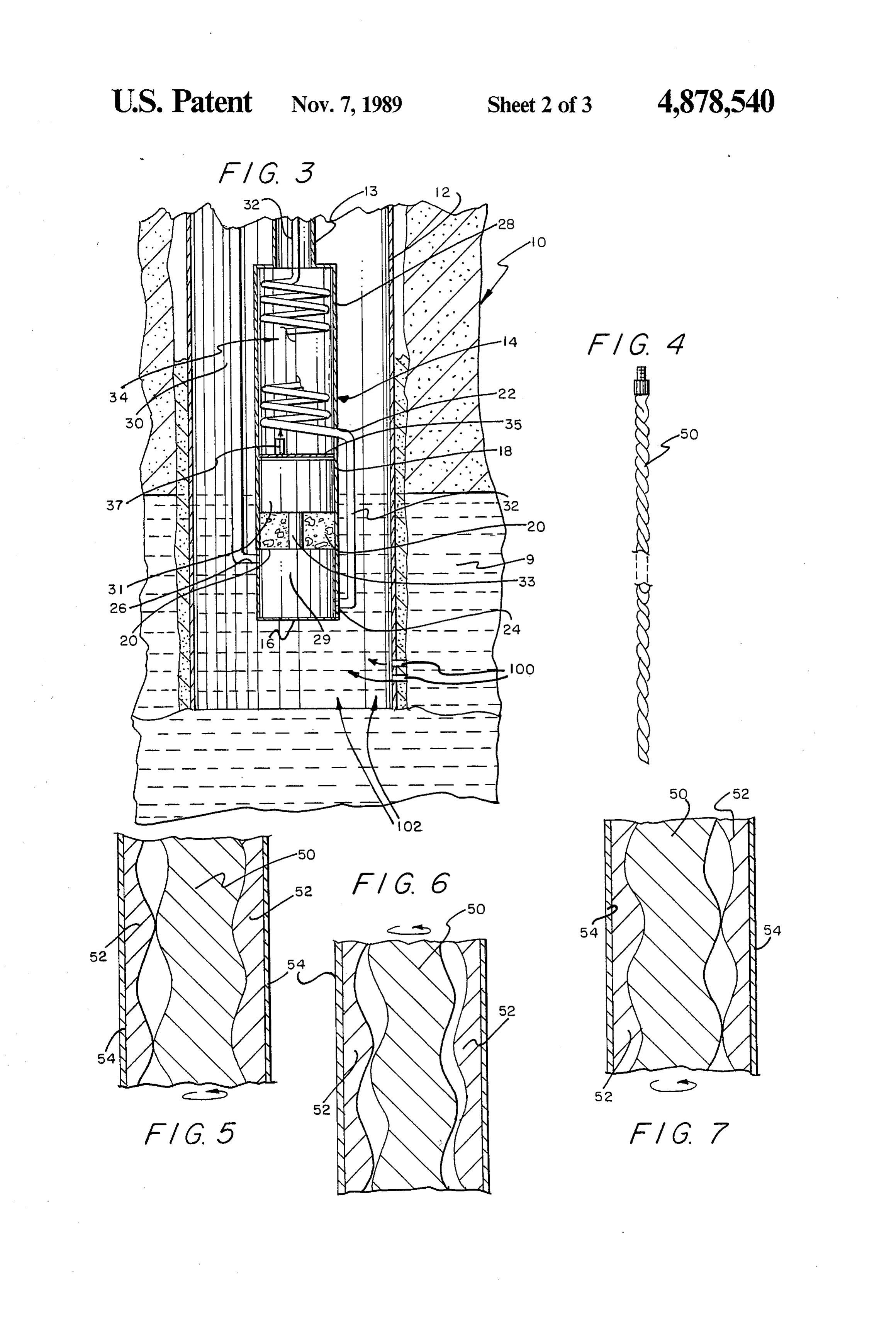
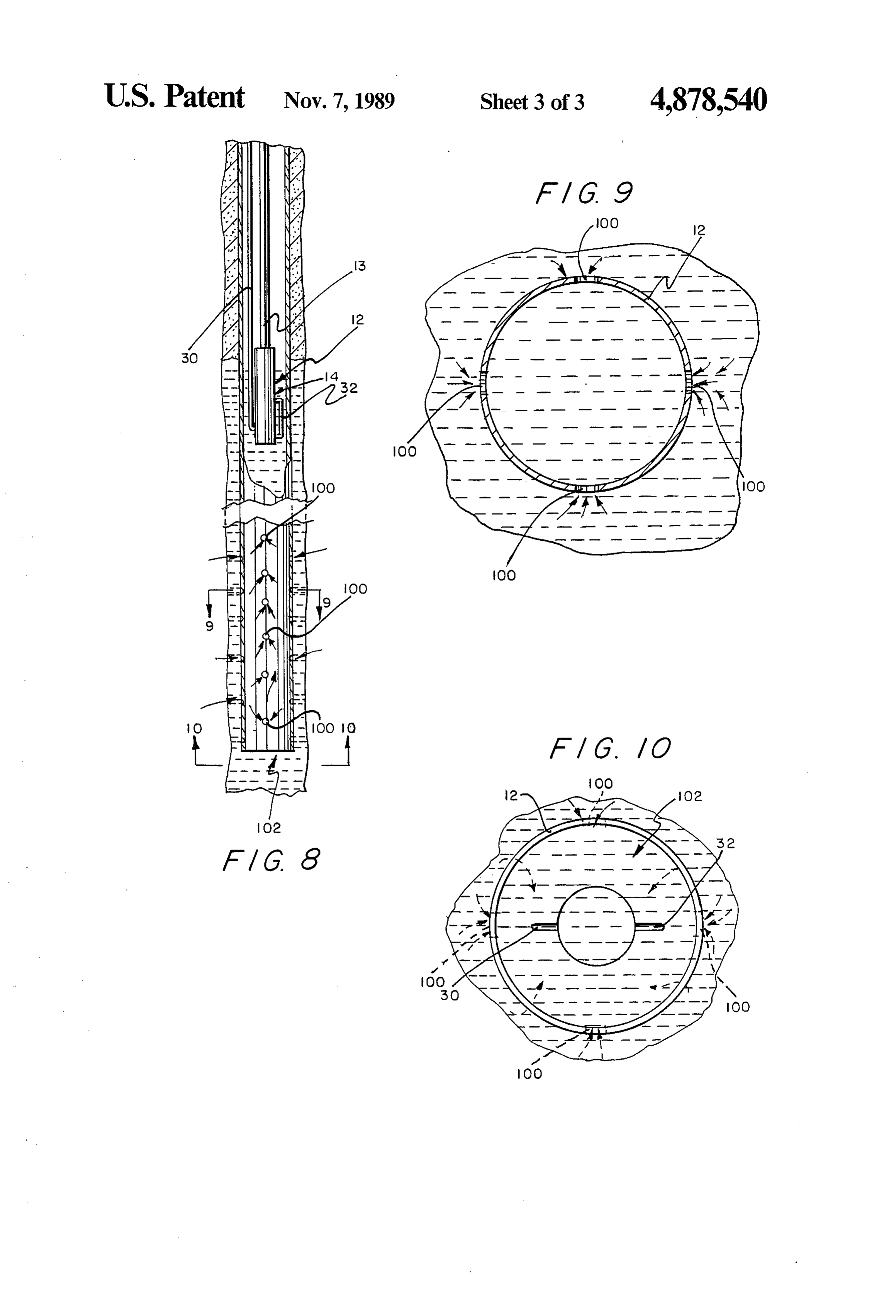
Page 6
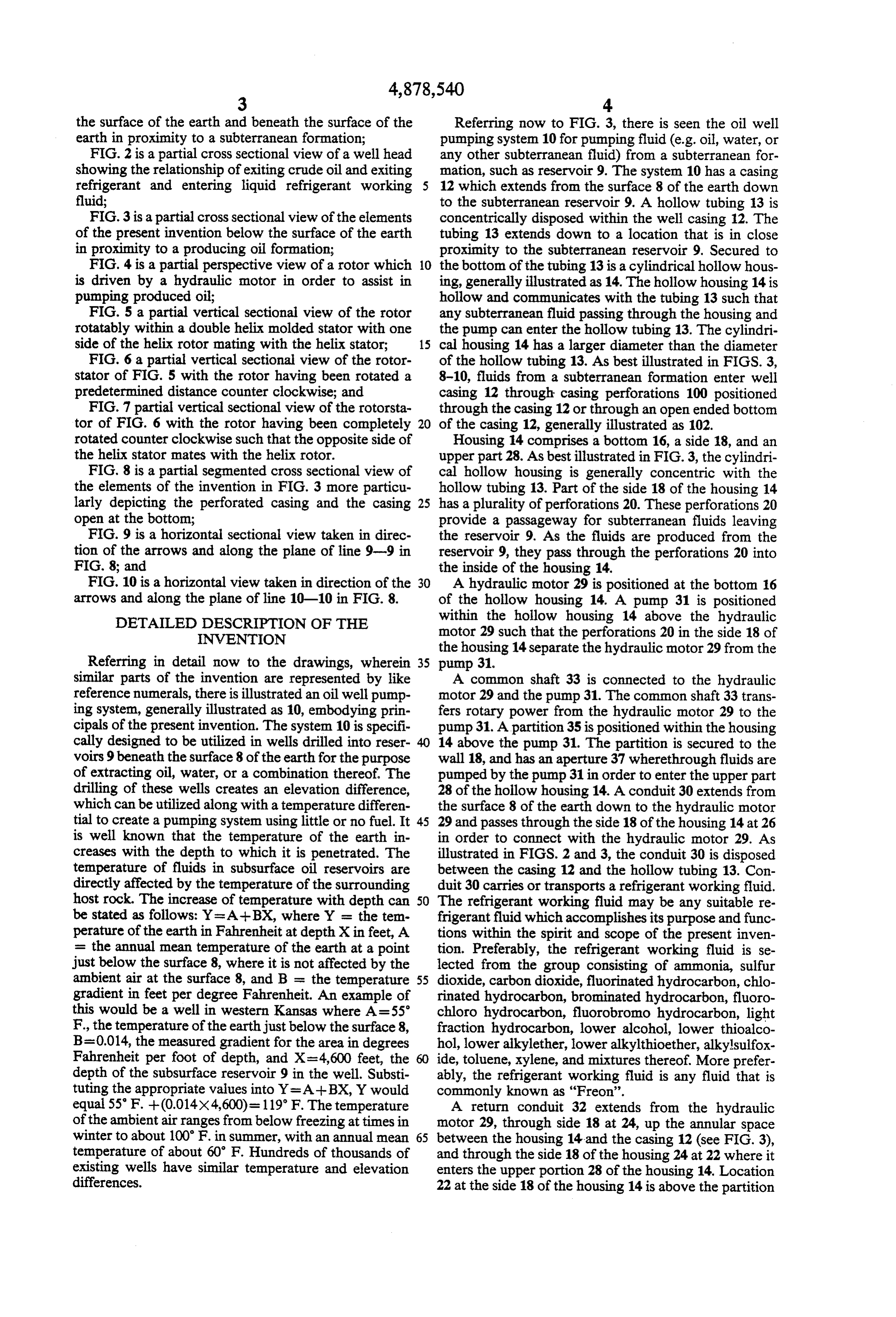
the surface of the earth and beneath the surface of the Referring now to FIG. 3, there is seen the oil well earth in proximity to a subterranean formation; pumping system 10 for pumping fluid (e.g. oil, water, or FIG. 2 is a partial cross sectional view of a well head any other subterranean fluid) from a subterranean for showing the relationship of exiting crude oil and exiting mation, such as reservoir 9. The system 10 has a casing refrigerant and entering liquid refrigerant working 12 which extends from the surface 8 of the earth down fluid; to the subterranean reservoir 9. A hollow tubing 13 is FIG.3 is a partial cross sectional view of the elements concentrically disposed within the well casing 12. The of the present invention below the surface of the earth tubing 13 extends down to a location that is in close in proximity to a producing oil formation; proximity to the subterranean reservoir 9. Secured to FIG. 4 is a partial perspective view of a rotor which 10 the bottom of the tubing 13 is a cylindrical hollow hous is driven by a hydraulic motor in order to assist in ing, generally illustrated as 14. The hollow housing 14 is pumping produced oil; hollow and communicates with the tubing 13 such that FIG. 5 a partial vertical sectional view of the rotor any subterranean fluid passing through the housing and rotatably within a double helix molded stator with one the pump can enter the hollow tubing 13. The cylindri side of the helix rotor mating with the helix stator; 15 cal housing 14 has a larger diameter than the diameter FIG. 6 a partial vertical sectional view of the rotor of the hollow tubing 13. As best illustrated in FIGS. 3, stator of FIG. 5 with the rotor having been rotated a 8-10, fluids from a subterranean formation enter well predetermined distance counter clockwise; and casing 12 through casing perforations 100 positioned FIG. 7 partial vertical sectional view of the rotorsta through the casing 12 or through an open ended bottom tor of FIG. 6 with the rotor having been completely 20 of the casing 12, generally illustrated as 102. rotated counter clockwise such that the opposite side of Housing 14 comprises a bottom 16, a side 18, and an the helix stator mates with the helix rotor. upper part 28. As best illustrated in FIG. 3, the cylindri FIG. 8 is a partial segmented cross sectional view of cal hollow housing is generally concentric with the the elements of the invention in FIG. 3 more particu hollow tubing 13. Part of the side 18 of the housing 14 larly depicting the perforated casing and the casing 25 has a plurality of perforations 20. These perforations 20 open at the bottom; provide a passageway for subterranean fluids leaving FIG. 9 is a horizontal sectional view taken in direc the reservoir 9. As the fluids are produced from the tion of the arrows and along the plane of line 9-9 in reservoir 9, they pass through the perforations 20 into FIG. 8; and the inside of the housing 14. FIG. 10 is a horizontal view taken in direction of the 30 A hydraulic motor 29 is positioned at the bottom 16 arrows and along the plane of line 10-10 in FIG. 8. of the hollow housing 14. A pump 31 is positioned DETAILED DESCRIPTION OF THE within the hollow housing 14 above the hydraulic INVENTION motor 29 such that the perforations 20 in the side 18 of the housing 14 separate the hydraulic motor 29 from the
Referring in detail now to the drawings, wherein 35 pump 31.
similar parts of the invention are represented by like A common shaft 33 is connected to the hydraulic reference numerals, there is illustrated an oil well pump motor 29 and the pump 31. The common shaft 33 trans ing system, generally illustrated as 10, embodying prin fers rotary power from the hydraulic motor 29 to the cipals of the present invention. The system 10 is specifi pump 31. Apartition 35 is positioned within the housing cally designed to be utilized in wells drilled into reser 14 above the pump 31. The partition is secured to the voirs 9 beneath the surface 8 of the earth for the purpose wall 18, and has an aperture 37 wherethrough fluids are of extracting oil, water, or a combination thereof. The pumped by the pump 31 in order to enter the upper part drilling of these wells creates an elevation difference, 28 of the hollow housing 14. A conduit 30 extends from which can be utilized along with a temperature differen the surface 8 of the earth down to the hydraulic motor tial to create a pumping system using little or no fuel. It 45 29 and passes through the side 18 of the housing 14 at 26 is well known that the temperature of the earth in in order to connect with the hydraulic motor 29. As creases with the depth to which it is penetrated. The illustrated in FIGS. 2 and 3, the conduit 30 is disposed temperature of fluids in subsurface oil reservoirs are between the casing 12 and the hollow tubing 13. Con directly affected by the temperature of the surrounding duit 30 carries or transports a refrigerant working fluid. host rock. The increase of temperature with depth can 50 The refrigerant working fluid may be any suitable re be stated as follows: Y= A--BX, where Y = the tem frigerant fluid which accomplishes its purpose and func perature of the earth in Fahrenheit at depth Xin feet, A tions within the spirit and scope of the present inven = the annual mean temperature of the earth at a point tion. Preferably, the refrigerant working fluid is se just below the surface 8, where it is not affected by the lected from the group consisting of ammonia, sulfur ambient air at the surface 8, and B = the temperature 55 dioxide, carbon dioxide, fluorinated hydrocarbon, chlo gradient in feet per degree Fahrenheit. An example of rinated hydrocarbon, brominated hydrocarbon, fluoro this would be a well in western Kansas where A=55 chloro hydrocarbon, fluorobromo hydrocarbon, light F., the temperature of the earthjust below the surface 8, fraction hydrocarbon, lower alcohol, lower thioalco B=0.014, the measured gradient for the area in degrees hol, lower alkylether, lower alkylthioether, alkylsulfox Fahrenheit per foot of depth, and X=4,600 feet, the ide, toluene, xylene, and mixtures thereof. More prefer depth of the subsurface reservoir 9 in the well. Substi ably, the refrigerant working fluid is any fluid that is tuting the appropriate values into Y= A--BX, Y would commonly known as "Freon'.
equal 55' F. --(0.014x4,600)=119 F. The temperature A return conduit 32 extends from the hydraulic of the ambient air ranges from below freezing at times in motor 29, through side 18 at 24, up the annular space winter to about 100 F. in summer, with an annual mean 65 between the housing 14 and the casing 12 (see FIG. 3), temperature of about 60 F. Hundreds of thousands of and through the side 18 of the housing 24 at 22 where it existing wells have similar temperature and elevation enters the upper portion 28 of the housing 14. Location differences. 22 at the side 18 of the housing 14 is above the partition
Page 7
35. The return conduit 32 forms a helical shaped struc rounding subterranean atmosphere, the structure of the ture, generally illustrated as 32, in the upper portion of return conduit, etc.
the housing 14. This helical shaped structure 34 defines After leaving the section of the return conduit 32 that a heat exchange means that when refrigerant working is situated between the housing 14 and the casing 12, the fluid passes through the helical shaped structure, the refrigerant working fluid enters the helical structure (or heat from the subterranean fluids that are pumped 31 vaporizer) section of the return conduit 32. As was through aperture 37 vaporizes or boils the refrigerant indicated, the helical structure 34 is situated in the upper working fluid into a vapor state. After the return con portion 28 of the hollow housing 14 and the circuitous duit 32 has formed the helical structure 34, it continues structure enables the refrigerant working fluid to re generally concentric up the hollow wall tubing 13 to the 10 main in contact with the subterranean fluid that is being surface of the earth 8 where, as illustrated in FIG. 2, it pumped by pump 31 through aperture 34 into the upper leaves hollow tubing 13. portion 28 of the housing 14. The heat of the subterra Tubing 13 (as illustrated in FIG. 1) leads to oil stor nean fluid causes the refrigerant working fluid to start age tanks 40 and conducts or carries subterranean pro-. vaporizing within the helical structure 34. After the duced oil (or any other subterranean fluid) to the tanks 15 refrigerant working fluid is vaporized, it ascends within 40 for storage. Return conduit 32 extends to a con the return conduit 32 within the well tubing 13. Heated denser 42 where refrigerant vapors are cooled and con subterranean fluid is in continuous contact with conduit densed into a refrigerant liquid. After the refrigerant 32 as conduit 32 leaves the hollow housing 14 to ascend vapor is condensed into a liquid state by the condenser to the surface 8 of the earth. This heat causes the vapor 42, it is transported to a pump 44 which pumps the 20 ized refrigerant working fluid to remain in a vapor state refrigerant fluid through conduit 30 down to the hy while it rises within return conduit 32 to the surface 8 of draulic motor 29. Between the pump 44 and the con the earth. As is readily apparent, the produced subterra denser 42 may be a refrigerant storage tank (not shown nean fluid travels in the same direction within the well in the drawings). The storage tank may provide a reser tubing 13 as the vaporized refrigerant that ascends voir for storing refrigerant working fluid. There should 25 within return conduit 32. As the refrigerant working be provided a sufficient quantity of refrigerant working fluid is being vaporized within the helical structure 34, fluid to fill the conduit 30 with refrigerant fluid and the its hydrostatic pressure from its fluid state is released return conduit 32 with vapor. A sufficient quantity of because the fluid refrigerant liquid is being vaporized refrigerant working fluid should also be provided for into a gas where it returns through return conduit 32 to changes in the ratio of fluid to gas due to fluctuation of 30 the surface 8 of the earth in order to enter the condenser pressures and temperatures in the system 10 which may 42.
be caused by variation of the ambient air flowing The pump 31 of this invention may be any suitable through the condenser 42. pump that is capable of performing the appropriate As the refrigerant working fluid descends through functions in accordance with the features of the inven conduit 30 between the well tubing 13 and the casing 35 tion. Preferably, the pump 31 is of the type having only 12, it is in a liquid state and is gradually being heated two components producing a progressing cavity appli due to the change in temperature as the conduit goes cation. Therefore, the pump 31 comprises a rotor 50 and deeper down below the surface 8 of the earth. The a stator 52 that is encapsulated or circumscribed by a refrigerant working fluid passes through the side 18 at tube 54. The rotor 50 is the only moving part and is location 26 where it enters into the hydraulic motor 29, preferably a single external helix with a round cross causing the motor 29 to turn and impel rotary power on section. The stator 52 is a double internal helix that is the common shaft 33. As was indicated, hydraulic preferably precision molded of synthetic elastomer that motor 29 drives the pump 31 which receives oil, or any is permanently bonded within the steel tube 54. When other subterranean fluid, from the reservoir 9 through the rotor 50 turns within the stator 52, cavities form as the perforations 20 in the side 18 of the housing 14. The is illustrated in FIGS. 5, 6, and 7. The cavities progress pump 31, a preferred embodiment being discussed be from the bottom of the pump 31 which may be defined low, drives the oil to the surface 8 of the earth where it as the suction end to the top of the pump 31 which may flows into the storage tanks 40. be defined as the discharge end. As the cavities progress The hydraulic motor is an expansion means in the from the bottom to the top, they carry subterranean sense that there is a pressure drop between the location 50 formation fluids up through the pump 31 and into the 26 and the location 24 on the side 18 of the housing 14. upper section 28 of the housing 14. The progressing This expansion causes the refrigerant working fluid to cavities produce an effect like a rod pump that is contin cool in the lower part of the housing 14. The cooled ually on the up-stroke. The tight seals that are produced refrigerant working fluid is passed through the side 18 as the rotor 50 rotates within the stator 52 are created as at the location 24 and enters into return conduit 32 that 55 the rotor helices and the stator helices alternate be extends from hydraulic motor 29 through the annulus tween mating positions and keep the subterranean for between the casing 12 and the housing 14, and through mation fluids rising at a fixed rate, proportional to the the side 18 at location 22 to enter the upper portion 28 rotational speed of the rotor 50. The progressing cavity of the housing 14. As the cooled refrigerant working pump 31 may be any suitable pump 31 employing a fluid passes through return conduit 32 between the side rotor 50/stator 52, such as that purchased from the 18 of the housing 14 and the casing 12, it begins to be Robbins and Meyers Co. under the registered trade heated from the subterranean atmosphere, including mark MOYNO.
any heated subterranean fluids that may come in contact My invention will be illustrated by the following with the return conduit 32. The amount of heat im set-forth example which is given by way of illustration ported to the cooled refrigerant working fluid as it 65 and not by any limitation. All parameters such as tem flows through this section of return conduit 32 depends peratures, pressures, etc., submitted in this example are on a number of variables, such as the flow rate of the not to be construed to unduly limit the scope of my cooled refrigerant fluid, the temperature of the sur invention.
Page 8
EXAMPLE (b) a hollow tubing means having a known tubing diameter and disposed generally concentrically
The pressure and temperature for the process for within said well casing means down to a predeter pumping fluid from the subterranean reservoir 9 may be mined depth;
any suitable temperatures and pressures within the con (c) a generally cylindrical hollow housing having a fines of the physical properties (i.e., boiling tem housing diameter and a housing side wall is secured peratures/pressures, condensing temperatures/pres to the bottom of said hollow tubing means and is sures, etc.) of the refrigerant working fluid which may generally concentric therewith; be any suitable refrigerant including, but not limited to, (d) a motor means disposed at the bottom of said dichlorodifluoromethane (CCl2F2, Freon-12), C2Cl2F4 10 hollow housing;
(Freon-114), CCl3F (Freon-11), C2Cl3Fs (Freon-113), (e) a pump means disposed within said hollow hous SO, CO2, ammonia, and mixtures thereof. For the ing above said motor means; purposes of this example it will be assumed the liquid (f) a common shaft means connected to said motor refrigerant leaving the condenser 42 has a pressure of means and said pump means for interconnecting 0.30 psia and a temperature of 60' F. and a flow rate of 15 the motor means with the pump means such that 100 mol/hour (or 14,892 pounds per hour). The liquid the shaft means can transfer rotary power from the refrigerant chosen is Freon 13Bl which has a molecular motor means to the pump means, said housing side weight of about 148.92 and a density of 63.95 pounds/- wall immediately opposed to said common shaft cubic foot. After the liquid refrigerant is pressurized by 20 means having a structure defining a plurality of pump 44 to a pressure of 400 psia, it has a temperature apertures wherethrough subterranean fluids pass; of 60.2 F. and a density of 65.03 pounds/cubic foot. As (g) a partition means disposed within said hollow the liquid refrigerant is pumped down conduit 30 to an housing above said pump means, said partition assumed depth of 4,600 feet, the pressure increases since having a partition aperture wherethrough subterra the head pressure of the column of liquid refrigerant nean fluids are pumped by said pump means; increases with depth. The pressure in conduit 30 at 25 (h) an entrance conduit means extending from the location 26 where the pressurized liquid refrigerant is surface of the earth down to the motor means and about to enter housing 14 is about 2,400. The tempera through the housing side wall in order to connect ture of the liquid refrigerant at this pressure is about with the motor means, said entrance conduit means 121' F., and the refrigerant has a density of about 70.7 being disposed between said well casing means and pounds per cubic foot. As the liquid refrigerant draws 30 said hollow tubing means; and the hydraulic motor 29, an expansion of the liquid re (i) a return conduit means extending from said motor frigerant within the motor 29 occurs. This expansion means, through the housing side wall, upwardly has a cooling effect on the liquid refrigerant. The expan between the housing side wall and said wall casing sion causes a change of pressure of the liquid refrigerant 35 means, through the housing side wall above said from about 2,400 psia to about 150 psia. The cooling partition means, and through the hollow housing effect is from about 121 F. to about 30' F. At these above said partition means, and through the tubing conditions of temperature an pressure, the refrigerant is means to the surface of the earth. still in a liquid state. When the liquid refrigerant is in the 2. The apparatus of claim 1 wherein said pump means vaporizer (or helical structure 34), the vaporizer comes comprises a rotor rotatably disposed within a stator in contact with 130 F. crude oil which heats the liquid means, said rotor having a structure defining a single refrigerant to a temperature of about 88" F., causing the external helix.
liquid refrigerant to vaporize into a gaseous state with 3. The apparatus of claim 2 wherein the known tub an accompanying pressure drop to about 38 psia. The ing diameter is smaller than the housing diameter. gaseous Freon ascends to the surface 8 of the earth 45 4. The apparatus of claim 3 wherein the return con within return conduit 32 due to pressure between the duit means passing through said hollow housing above pressure (i.e., about 3.8 psia) at the location of the va said partition means has a helical disposition. porizer (or helical structure 34) and the pressure (i.e., 5. A process for pumping fluid from a subterranean about 38 psia) within the return conduit 32 on the sur reservoir to a surface of the earth comprising the steps face of the earth where the gaseous Freon enters the SO of:
condenser 42 to cool or chill the gaseous Freon into a (a) descending a refrigerant working fluid between a liquid state to start the process all over. well casing means and a well tubing means; While the present invention has been described (b) passing the refrigerant working fluid into a lower herein with reference to particular embodiments part of a housing secured to the bottom of the well thereof, a latitude of modification, various changes and 55 tubing means;
substitutions are intended in the foregoing disclosure, (c) cooling the refrigerant working fluid in the lower and it will be appreciated that in some instances some part of the housing;
features of the invention will be employed without a (d) passing the cooled refrigerant working fluid of corresponding use of other features without departing step (c) out of the lower part of the housing; from the scope of the invention as set forth. (e) heating the cooled refrigerant working fluid of I claim: step (d);
1. An apparatus for pumping fluid from a subterra (f) passing the heated refrigerant working fluid of nean reservoir comprising: step (e) into an upper part of the housing, said (a) a well casing means extending from a surface of refrigerant working fluid of steps (a)-(e) being at a the earth down to a subterranean reservoir, said 65 pressure and temperature such as to be in a liquid well casing means having at least one casing perfo State;
ration wherethrough fluid enters therein from said (g) heating the heated refrigerant working fluid of subterranean reservoir; step (f) in the upper part of the housing in order to
Page 9
vaporize the refrigerant working fluid into a vapor; 9. The process of claim 8 wherein said heating step and (g) comprises employing the subterranean fluid. (h) ascending the vapor of step (g) through the well 10. The process of claim 9 additionally comprising tubing means to the surface of the earth. flowing the subterranean fluid through the well tubing 6. The process of claim 5 additionally comprising 5 means in the same direction that said vapor of step (h) condensing the vapor of step (h) on the surface of the ascends.
earth into the refrigerant working fluid. 11. The process of claim 10 additionally comprising 7. The process of claim 6 additionally comprising heating the refrigerant working fluid of step (a) as it producing a subterranean fluid through perforations in descends.
the housing above the location where the refrigerant O 12. The process of claim 11 wherein said refrigerant working fluid of step (b) is passed into the housing. working fluid is selected from the group consisting of 8. The process of claim 7 additionally comprising sulfur dioxide, carbon dioxide, fluoronated hydrocar pumping the subterranean fluid from a location in the bon, chlorinated hydrocarbon, brominated hydrocar housing above the location where the subterranean fluid bon, fluorochlorohydrocarbon, fluorobromo hydrocar is produced through the perforations in the housing and 15 bon, light fraction hydrocarbon, lower alcohol, lower below the locations in the housing where the heated thioalcohol, lower alkyl ether, lower alkylthioether, refrigerant working fluid of step (f) is passed into the alkylsulfoxide, toluene, xylene, and mixtures thereof. upper part of the housing. is it is is :
Provenance
- Collection
- Cited prior art
- Original PDF
- patentimages.storage.googleapis.com →
- Filed
- 1988-06-22
- Pages
- 9
- Method
- pdftotext (the PDF's own text layer) + pdftoppm 300dpi page scans
- Source
- Google Patents bibliographic record
- Granted
- 1989-11-07
- Inventors
- William M. Raymond
- Transcribed from
- patentimages.storage.googleapis.com →