patent · US4585950
Wind turbine with multiple generators
29 April 1986
Page 1 — bibliographic record
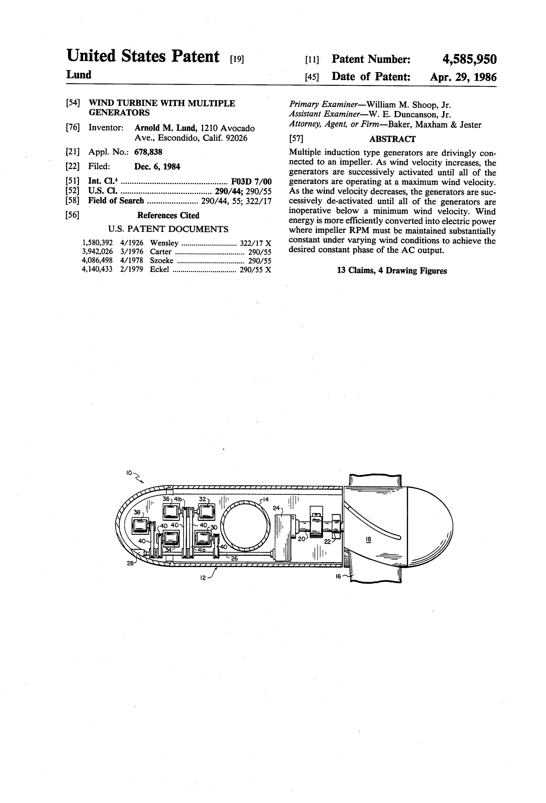
United States Patent (19) 11). Patent Number: 4,585,950 Lund 45) Date of Patent: Apr. 29, 1986 54) WIND TURBINE WITH MULTIPLE Primary Examiner-William M. Shoop, Jr. GENERATORS Assistant Examiner-W. E. Duncanson, Jr. 76) Inventor: Arnold M. Lund, 1210 Avocado Attorney, Agent, or Firm-Baker, Maxham & Jester Ave., Escondido, Calif. 92026 57 ABSTRACT 21 Appl. No.: 678,838 Multiple induction type generators are drivingly con 22) Filed: Dec. 6, 1984 nected to an impeller. As wind velocity increases, the generators are successively activated until all of the 51 Int. Cl." ................................................ F03D 7/00 generators are operating at a maximum wind velocity. (52) U.S. C. ......................................... 290/44; 290/55 As the wind velocity decreases, the generators are suc 58) Field of Search ....................... 290/44, 55; 322/17 cessively de-activated until all of the generators are 56 References Cited inoperative below a minimum wind velocity. Wind energy is more efficiently converted into electric power
1,580,392 4/1926. Wensley ............................ 322/17 X constant under varying wind conditions to achieve the 3,942,026 3/1976 Carter ................................... 290/55 desired constant phase of the AC output. 4,086,498 4/1978 Szoeke .................................. 290/55 4,140,433 2/1979 Eckel ................................ 290/55 X 13 Claims, 4 Drawing Figures
arzazzazaaaaaaaaaaaaaa E
Page 2
Drawing sheet — no readable text.
Page 3
Drawing sheet — no readable text.
Page 4
WINDTURBINE WITH MULTIPLE GENERATORS
According to the present invention, multiple induc tion type generators are drivingly connected to an im peller. As wind velocity increases, the generators are
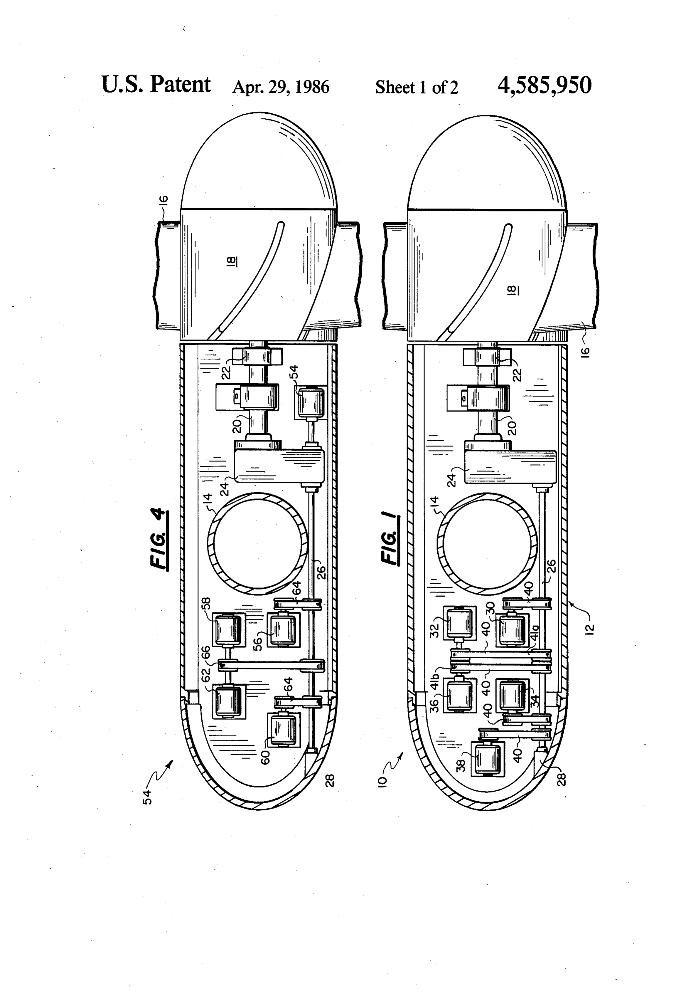
BACKGROUND OF THE INVENTION successively activated until all of the generators are The present invention relates to electric power gener operating at a maximum wind velocity. As the wind ating systems, and more particularly, to wind powered velocity decreases, the generators are successively de generating systems. activated until all of the generators are inoperative For centuries windmills have been used to harness the below a minimum wind velocity. Wind energy is more energy of the wind to grind wheat, operate water efficiently converted into electric power where impel pumps and drive various other machines. More re 0 ler RPM must be maintained substantially constant cently, wind powered turbines have been connected to under varying wind conditions to achieve the desired generators for producing electric power. constant phase of the AC output. The ever increasing cost of energy has lead to re BRIEF DESCRIPTION OF THE DRAWINGs newed interest in systems which generates electric 15 power from the wind. Such systems are generally reli FIG. 1 is a simplified plan view of the mechanical able, can be used in many locations, are an alternative to components contained within the nacelle of a first em expensive fossil fuels, and are non-polluting. These fac bodiment of my invention.
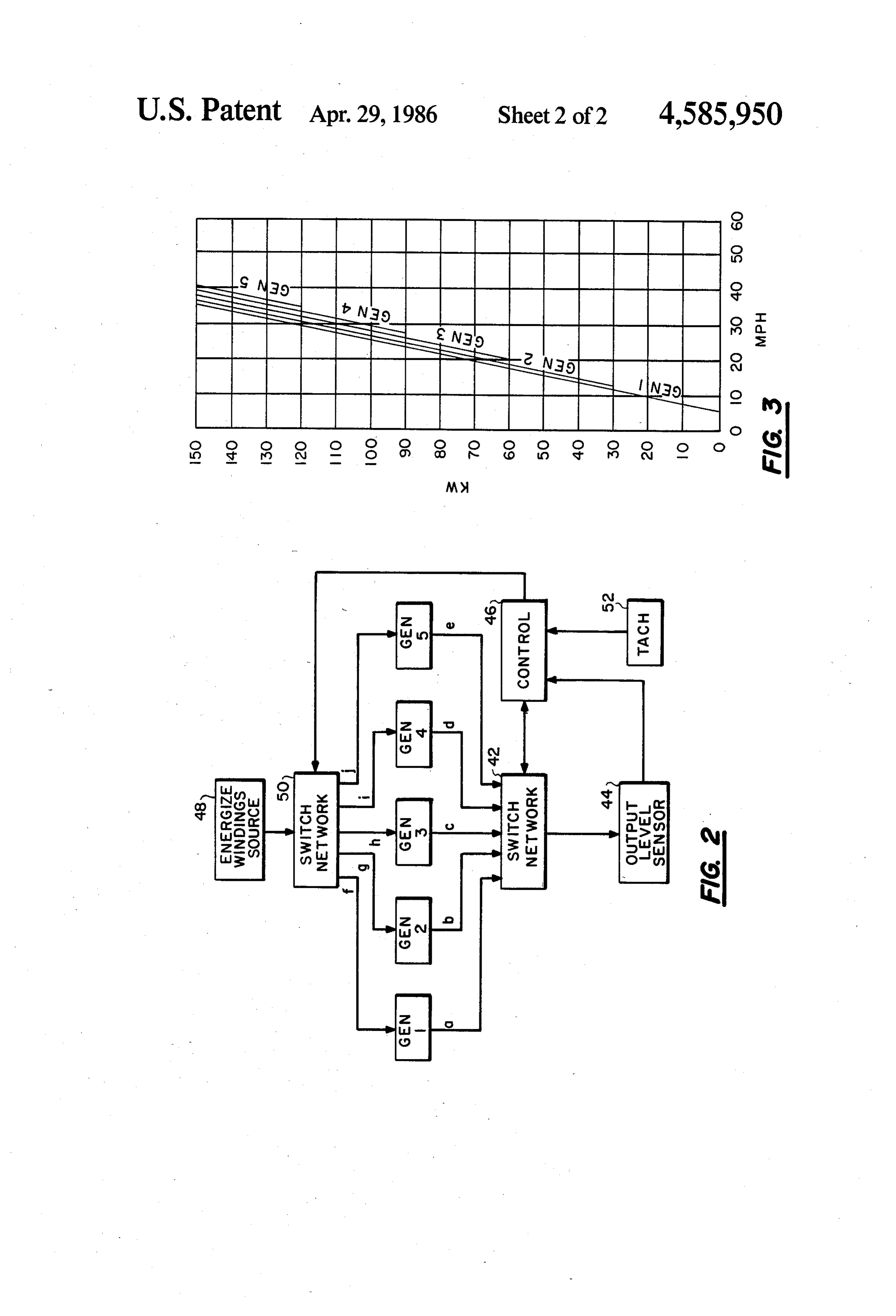
tors make such systems particularly attractive as a par FIG. 2 is a block diagram illustrating the manner in tial solution to the energy crisis. which the generators of the first embodiment of my It is desirable for the output of a wind driven electric 20 invention are controlled.
FIG. 3 is a graph depicting the operation of the gen power generating system to have an AC output with a phase, such as sixty cycles per second, which is compat erators of the first embodiment of my invention over a ible with the phase of electric power supplied by utili wide range of wind velocities.
ties. This permits the output of the system to be directly FIG. 4 is a simplified plan view of the mechanical used in the home with appliances, lights and other de 25 embodiment components contained within the nacelle of a second of my invention.
vices without the use of any DC to AC converters.
Also, this enables the output of the wind driven system DESCRIPTION OF THE PREFERRED to be directly connected into the utility power grid. EMBODIMENTS Because of this, most commercial systems for producing 30 The entire disclosure of my co-pending U.S. patent electric power from the wind utilize AC or induction application Ser. No. 599,934 filed Apr. 13, 1984 entitled type generators. DC generators are less desirable for "Wind Powered Generator" is specifically incorporated wind driven systems because their brush structures herein undergo heavy wear and because electronic DC to AC poweredbygenerator reference. That application discloses a wind which utilizes an impeller with con power conversion circuitry is then required.
In order for an AC generator to provide electric stant chord and progressive pitch blades configured
current at a predetermined desired frequency, the input Itaccording also to a specific formula for maximum efficiency.
discloses a supporting tower having an elevator shaft of the generator must be driven at a substantially for raising and lowering the nacelle, and a special foun constant RPM. Therefore, such wind powered generat dation structure for the tower. The system disclosed in ing systems do not operate efficiently over a wide range that application includes a three of wind velocities. This problem can be partially solved generator which is driven by thephase commutating impeller. A servo by automatically varying the pitch of the blades, by circuit adjusts movable brushes in the generator to using air brakes on the blades, by using governor mech cause it to produce the maximum electric power output anisms, and other devices. These devices allow the with a constant impeller RPM and a phase compatible rotor of the generator to resist over spinning. Increased 45 with the utility power grid. The invention described torque on the blades is translated into higher power herein output, rather than higher impeller RPM. However, the Ser. No.is 599,934 an alternate approach to the invention of my aforementioned approaches generally waste or ignore a ing electric powerinvention over a for more efficiently generat wide range of wind velocities.
large proportion of the wind energy which could other wise be translated into electric power. One prior art 50 wind powered generator includesembodiment Referring to FIG. 1, a first a nacelle 12
mounted wind turbine utilizes a small light load generator at low about the upper end of a cylindrical tower 14 for rota wind velocities and then switches over to a large, heavy tion about a vertical axis. An impeller having a plurality load generator at high wind velocities. Both of the of blades 16 is mounted at the aft end of the nacelle for generators do not operate simultaneously and consider rotation about a horizontal axis. The blades 16 are able efficiency is lost in stepping between a single small 55 bolted to a splined hub 18 mounted over the aft end of generator and a single large generator. a shaft 20. This arrangement of nacelle, tower and im SUMMARY OF THE INVENTION peller insures that the nacelle will “weather vane' or rotate
Accordingly, it is the primary object of the present stantially so that the longitudinal axis of the nacelle is sub invention to provide an improved wind powered sys impeller blades parallel to the direction of the wind. Thus, the 16 extend substantially perpendicular to tem for more efficiently generating electric power the direction of the wind, for most efficient extraction under varying wind conditions. of wind energy. The forward end of the nacelle is ta It is another object of the present invention to pro pered or streamlined as is conventional. vide an improved wind turbine capable of transforming Referring still to FIG. 1, the intermediate portion of a larger proportion of wind power into electric power 65 the shaft 20 is rotatably journaled in a pillow block 22. over a wider range of wind velocities than conventional The forward end of the shaft 20 is drivingly connected systems, without utilizing complex mechanical or elec to a gear reduction mechanism 24 which in turn drives tronic mechanisms. a shaft 26 at a higher RPM than the shaft 20. The for
Page 5
ward end of the shaft 26 is journaled in another pillow circuit 46 by monitoring signals from the output level block 28. A significant feature of my invention is that sensor circuit 44. When the recommended output level the nacelle is balanced on either side of the tower 14. As of the first generator is exceeded by a certain amount, illustrated in FIG. 1, the impeller and gear reduction for example one kilowatt, the control circuit 46 com mechanism are mounted inside the nacelle 12 on one mands the second switch network 50 to energize the side of the tower 14. A plurality of induction type gen windings of the second generator in addition to the erators 30, 32, 34, 36 and 38 are mounted inside the windings of the first generator. The first generator is nacelle on the other side of the tower 14. The drive not deactivated. At the same time, the control switch 46 shaft 26 straddles or bypasses the tower 14 on one side commands the first switch network 42 to feed the elec thereof for drivingly connecting the impeller and the 10 tric power output of the second generator to the output generators.
level sensor
In the first embodiment 10 of my invention, each of generator is fed to thecircuit 44. Only the output of the second the generators is designed to operate at the same rota output of the first generator. output level sensor, and not the tional speed, for example 1800 RPM. Also, each of the generators is designed to produce approximately the 15 cutAsin illustrated at a wind in FIG. 3, the second generator may velocity of approximately twelve miles same maximum electric power output (sixty cycles per hour. In a similar fashion,
AC), for example thirty kilowatts. The rotors of each of creases, the control circuit 46 as the wind velocity in the generators are drivingly connected to the shaft 26 electric power produced by the second the monitors amount of generator and by respective endless timing belts 40. Each belt 40 is activates the third, fourth and fifth generators in succes entrained at one end about a pulley 41a on the input 20 shaft of the corresponding generator and at the other sion at approximately twenty miles per hour, twenty end about a pulley 41b mounted on the drive shaft 26. seven miles per hour and thirty-three miles per hour, Thus, there is a positive driving connection between the respectively. Thus, all of the generators are activated impeller and the rotors of each of the five generators. In when the wind velocity exceeds a predetermined maxi mum, which in the illustrated example is approximately the first embodiment of my invention, the pulleys are all 25 thirty-three of equal size so that the rotors of all five generators are miles per hour. driven at the same RPM. As the wind velocity decreases, the generators are The operation of the first embodiment 10 of my wind successively de-activated, one at a time. For example, powered generator will now be described in conjunc when the control circuit 46 determines that the output tion with FIG. 2. The generators 30, 32, 34, 36 and 38 30 of the fifth generator has dropped below its rated capac are illustrated in FIG. 2 as GEN 1, GEN 2, GEN 3, ity by a predetermined amount, for example five kilo GEN 4, and GEN 5. The power output of the genera watts, it commands the second switch network 50 to tors is fed on lines a, b, c, d and e through a first switch de-activate the windings of the fifth generator. This network 42 to an output level sensor circuit 44. A con occurs when the wind velocity drops below approxi trol circuit 46 commands the first switch network 42 to 35 mately thirty-three miles per hour in the illustrated selectively feed the output of one of the generators to example as indicated in the graph of FIG. 5. Similarly, the output level sensor circuit 44. The control circuit 46 when the wind velocity drops below approximately commands the first switch network 42 based upon infor twenty-seven miles per hour, the fourth generator is mation received from the output level sensor circuit 44. de-activated. The third, second and first generators are The induction generators are of the conventional type 40 de-activated in succession when the wind velocity in that power will be generated only if the stator or drops below approximately twenty miles per hour, rotor windings are energized. A source of power 48 for twelve miles per hour and seven miles per hour, respec energizing the windings is connected through a second tively. Thus, when the wind velocity is below a prede switch network 50 and through lines f, g, h, i and j to termined minimum, which is approximately seven miles each of the generators. The control circuit 36 com 45 per hour in the illustrated example, all of the generators mands the second switch network 50 to selectively are de-activated and the impeller idles at a low speed. connect the power source 48 to one or more of the It should be understood that in some situations the generators, or to disconnect the power source 48 from wind velocity may increase only enough for the first, all the generators. The control circuit 46 also receives second and third generators to cut-in at which time the information regarding the impeller RPM from a ta 50 wind velocity will begin to decrease. As the wind ve chometer 52. locity decreases, then the third, second and first genera The manner in which the control circuit 46 (FIG. 2) tors will be successively de-activated. The system may commands the first and second switch networks 42 and not ramp all the way through all the generators and 50 will now be described in conjunction with FIGS. 2 may, for example, fluctuate between a state in which and 3. When the wind velocity exceeds a predetermined 55 three of the generators are operating and four of the minimum, for example approximately seven miles per generators are operating. This would occur in the illus hour, the control circuit 46 commands the second trated example if the wind velocity fluctuated between switch network 50 to energize the windings of the first approximately twenty-five miles per hour and thirty generators. The predetermined minimum wind velocity miles per hour.
will rotate the impeller at a corresponding desired RPM 60 It will be observed that in the first embodiment of my which is sensed by the control circuit 46 through the invention the weight of the impeller and the gear reduc tachometer 52. Thus, the first generators produces elec tion mechanism mounted in the nacelle on one side of tric power. The control circuit 46 commands the first the tower is balanced by the weight of the five genera switch network 42 to feed the electric power from the tors mounted in the nacelle in the other side of the first generator to the output lever sensor circuit 44. 65 tower. This facilitates rotation of the nacelle around the As the velocity of the wind increases, eventually the tower as the direction of the wind changes and reduces electric power output of the first generator will begin to the stress on the bearing structures rotatably mounting exceed its capacity. This is determined by the control the nacelle to the tower.
Page 6
FIG. 4 illustrates a second embodiment 54 of my a vertical support tower extending through the na invention. It is similar to the first embodiment except celle; and, that one generator 54 of the five generators is connected means for mounting the nacelle for rotation about the to the aft end of the drive shaft 26. Also, the five genera tower for orientation into the wind. tors 54, 56, 58, 60 and 62 have different rated power 7. A wind powered generator according to claim 6 outputs and are designed to operate at different RPMs. wherein the impeller is mounted at one end of the na For example, the generator 54 may be rated at ten kilo celle on one side of the tower, the generators are watts at 1200 RPM. The generator 56 may be rated at mounted in the nacelle on the other side of the tower, thirty kilowatts at 1200 RPM. The generator 58 may be and the driving connection means extends within the rated at forty kilowatts at 1800 RPM. The generator 60 10 nacelle around the tower, so that the nacelle is balanced may be rated at twenty kilowatts at 1200 RPM. And for rotation about the tower.
finally the generator 62 may be rated at twenty kilo 8. A wind powered generator according to claim 7 watts at 1800 RPM. The gear reduction mechanism 24 wherein at least one of the generators is mounted in the has a ratio such that when the impeller is rotating at its nacelle on the one side of the tower and the remaining constant preferred RPM, the input shaft of the first 15 generators are mounted in the nacelle on the other side generator 54 will be driven at 1200 RPM. Pulleys of of the tower.
equal diameter and associated drive belts 64 are then 9. A wind powered generator comprising: used to drivingly connect the shaft 26 with the input an impeller;
shafts of the generators 56 and 60, which are also driven means for supporting the impeller for rotation by the at 1200 RPM. Different size pulleys are then used with 20 wind;
a drive belt 66 in drivingly connecting the input shafts a plurality of generators each having an input shaft; of the generators 58 and 62 with the shaft 26 so that transmission means for providing a continuous driv these last generators will be driven at 1800 RPM when ing connection between the impeller and the input the other generators are driven at 1200 RPM. The gen shaft of each of the generators for continuous co erators of my second embodiment are successively acti 25 rotation thereof; and vated as the wind velocity increases and are succes control means responsive to wind velocity for acti sively de-activated as the wind velocity decreases in the vating a first one of the generators when the wind same manner as described in conjunction with the first velocity exceeds a predetermined minimum, for embodiment of my invention. successively activating additional ones of the gen Having described preferred embodiments of my wind 30 erators as the wind speed increases until all of the powered generator, it should be apparent to those generators are activated when the wind velocity skilled in the art that my invention may be modified in exceeds a predetermined maximum, for de-activat both arrangement and detail. Therefore, the protection ing a first one of the generators when the wind afforded my invention should only be limited in accor velocity falls below the predetermined maximum, dance with the scope of the following claims. 35 and for successively de-activating additional ones I claim: of the generators as the wind velocity decreases 1. A wind powered generator comprising: until all of the generators are de-activated when the an impeller; wind velocity is below the predetermined mini means for supporting the impeller for rotation by the l wind; 40 10. A wind powered generator according to claim 9 a plurality of generators each having an input shaft; wherein said control means activates the generators by means providing a continuous driving connection energizing windings therein.
between the impeller and the input shaft of each of 11. A wind powered generator according to claim 9 the generators for continuous co-rotation thereof; wherein at least two of the generators have different and 45 power output levels when they are activated. control means responsive to wind velocity for succes 12. A wind powered generator according to claim 9 sively activating the generators as the wind veloc wherein at least two of the generators operate at differ ity increases and for successively de-activating the ent RPMs and the driving connection means includes generators as the wind velocity decreases. drive ratio means for enabling the two generators to be 2. A wind powered generator according to claim 1 50 simultaneously driven at their different operating RPMs wherein said plurality of generators is greater than two. by the impeller.
3. A wind powered generator according to claim 1 13. A wind powered generator comprising: wherein said control means activates the generators by an impeller;
energizing windings therein. means for supporting the impeller for rotation by the 4. A wind powered generator according to claim 2 55 wind;
wherein at least two of the generators have different a plurality of generators each having an input shaft; power output levels when they activated. transmission means for providing a continuous driv 5. A wind powered generator according to claim 2 ing connection between the impeller and the input wherein at least two of the generators operate at differ shaft of each of the generators for continuous co ent RPMs and the driving connection means includes 60 rotation thereof; and drive ratio means for enabling the two generators to be control means responsive to wind velocity for selec simultaneously driven at their different operating RPMs tively and simultaneously activating one or more of by the impeller. the generators for maximizing the amount of elec 6. A wind powered generator according to claim 1 tric power produced under varying wind velocities and further comprising: 65 while maintaining a substantially constant impeller a nacelle housing the generators and the driving con RPM.
nection means; k k k k sk
Provenance
- Collection
- Cited prior art
- Original PDF
- patentimages.storage.googleapis.com →
- Filed
- 1984-12-06
- Pages
- 6
- Method
- pdftotext (the PDF's own text layer) + pdftoppm 300dpi page scans
- Source
- Google Patents bibliographic record
- Granted
- 1986-04-29
- Inventors
- Arnold M. Lund
- Transcribed from
- patentimages.storage.googleapis.com →