patent · US6165339
Apparatus and method for controlling molecular cluster in fluid
26 December 2000
Page 1 — bibliographic record
United States Patent (19) 11 Patent Number: 6,165,339 Ibbott (45) Date of Patent: Dec. 26, 2000 54 APPARATUS AND METHOD FOR OTHER PUBLICATIONS
CONTROLLING MOLECULAR CLUSTER IN
FLUID D. Hadfield, Permanent Magnets and Magnetism, Iliffe Books Ltd., London, 1962, pp. 314-315, month of publica tion not available.
(75) Inventor: Jack Kenneth Ibbott, Tokyo, Japan
F.A. Lowenheim, Electroplating, McGraw-Hill Book Co., 73) Assignee: Makiko Yoshida, Tokyo, Japan New York, 1978 month of publication not available, pp.
21 Appl. No.: 08/747,027 Eric M. Rogers, “Physics for the Inquiring Mind', Princeton University Press, twelfth printing, 1977 month of publication 22 Filed: Nov. 7, 1996 not available, pp. 535, 580. Dr. Charles Wallach, “The Ion Controversy”, Belle Lumiere
Related U.S. Application Data Pty Limited (Australian Edition), 1983 month of publication Provisional application No. 60/006,297, Nov. 7, 1995. not available, pp. 28-29, 40-41. Int. Cl." ................................ C02F 1/46; CO2F 1/48 Primary Examiner Kathryn Gorgos U.S. C. ... 204/554; 204/557; 204/571; ASSistant Examiner William T. Leader 204/660; 204/664; 204/670; 204/671; 204/672; Attorney, Agent, or Firm Wenderoth, Lind & Ponack, 204/673; 205/742; 205/745; 210/222; 210/695; LLP.
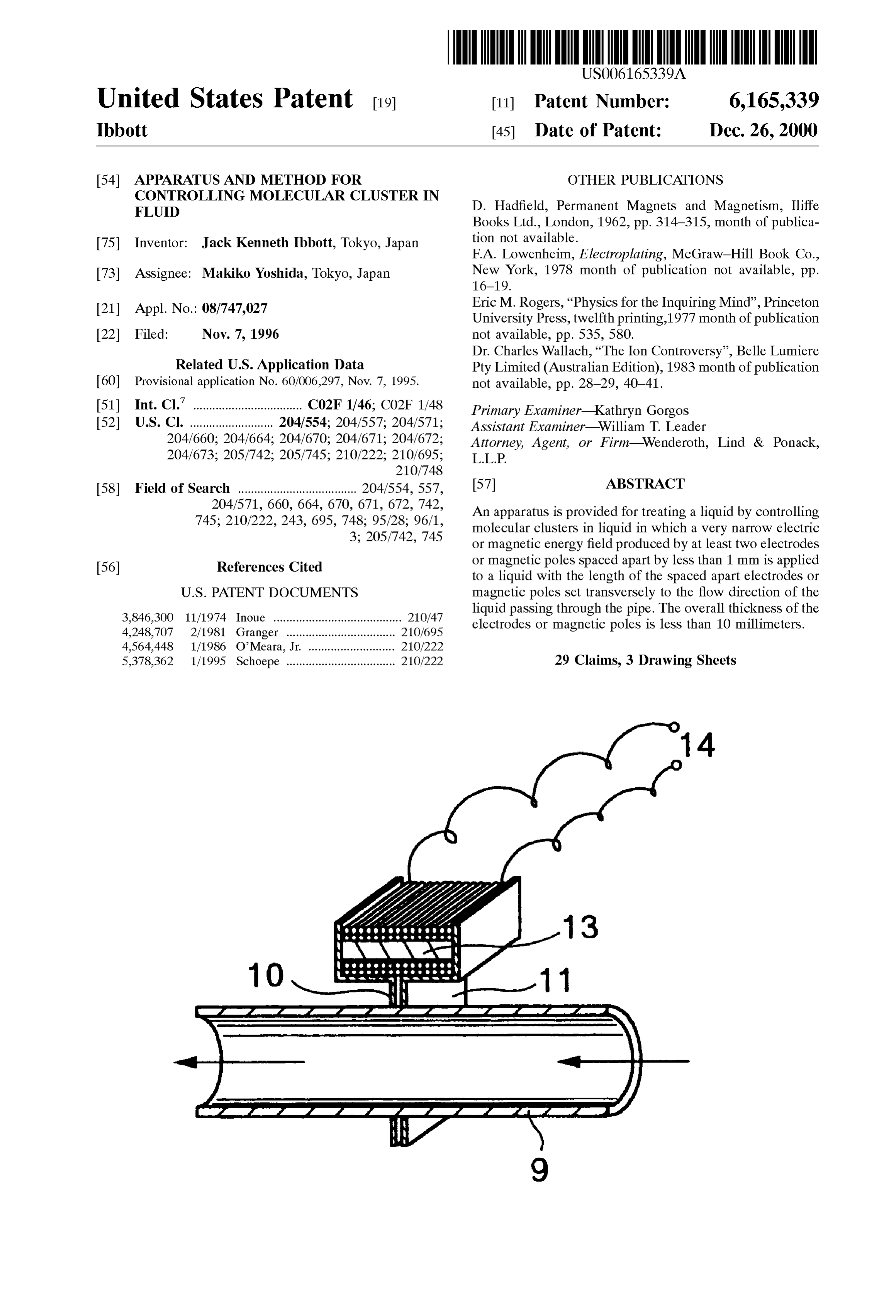
58 Field of Search ..................................... 204/554, 557, 57 ABSTRACT 204/571, 660, 664, 670, 671, 672, 742, An apparatus is provided for treating a liquid by controlling 745; 210/222, 243, 695, 748; 95/28; 96/1, molecular clusters in liquid in which a very narrow electric 3; 205/742, 745 or magnetic energy field produced by at least two electrodes 56) References Cited or magnetic poles Spaced apart by less than 1 mm is applied to a liquid with the length of the Spaced apart electrodes or
3,846,300 11/1974 Inoue ........................................ 210/47 liquid passing through the pipe. The Overall thickness of the 4,248,707 2/1981 Granger ....... ... 210/695 electrodes or magnetic poles is less than 10 millimeters. 4,564,448 1/1986 O’Meara, Jr. ... ... 210/222 5,378,362 1/1995 Schoepe .................................. 210/222 29 Claims, 3 Drawing Sheets
YYYYYYYYYYY.
Page 2
Drawing sheet — no readable text.
Page 3
Drawing sheet — no readable text.
Page 4
Drawing sheet — no readable text.
Page 5
APPARATUS AND METHOD FOR molecular cluster Size in the liquid by the application of an CONTROLLING MOLECULAR CLUSTER IN electric field or magnetic field.
FLUID To achieve the above object, the present invention pro vides an apparatus in which a very narrow electric or
This application claims the benefit of U.S. Provisional 5 magnetic energy field produced by at least two electrodes or Application No. 60/006,297 filed Nov. 7, 1995. magnetic poles Spaced apart by leSS than 1 mm is applied to a liquid with the length of the Spaced apart electrodes or
BACKGROUND OF THE INVENTION magnetic poles Set transversely to the flow direction of the 1. Field of the Invention liquid passing through a pipe. The overall thickness of the electrodes or magnetic poles is less than 10 millimeters.
The present invention relates to an apparatus and method Preferably, the present apparatus comprises a first annular for treating a liquid by controlling molecular cluster size in thin electrode member having a thickness, the first annular a liquid by applying an electric or magnetic field to a flowing thin electrode member encircling the pipe, and a Second liquid. annular thin electrode member having a thickness, the 2. Description of the Related Art 15 Second annular thin electrode member encircling the pipe; A device for treating liquid by using two electrodes wherein the first annular thin electrode member and the having different electrochemical potentials disposed inside Second annular thin electrode member are Spaced apart by of a pipe through which liquid flows is provided in U.S. Pat. less than 1 millimeter, and a combined thickness of the first No. 5,387.324 by the present inventor. In this device at least annular thin electrode member and the Second annular thin Some of the electrically conductive material of one of the electrode member is less than 10 millimeters. electrodes is disposed downstream of all of the electrically The first annular thin electrode member and the second conductive material of the other of the electrodes, So that annular thin electrode member can be disposed within the liquid flowing axially through the pipe Sequentially contacts pipe.
the electrodes and is only acted on by the downstream Alternatively, the pipe may have a first pipe Section and electrode before flowing from the pipe. By using a carbon 25 a Second pipe Section, and the first annular thin electrode electrode on the upstream Side and an iron electrode on the member and the Second thin electrode member can be downstream Side, the device will remove iron oxide colora disposed between the first and Second pipe Sections with a tion of the liquid. portion of the first and Second annular thin electrode mem Also provided by the present inventor is a method and ber being eXposed to the interior of the pipe. apparatus for preventing the deposition of calcium and Also, according to the present invention, the first and magnesium scale, as shown in U.S. Pat. No. 5,480,522, by Second annular thin electrode members Set forth above can which positive and negative electrodes of electrically con be replaced with first and Second thin magnetic pole pieces, ductive materials having different electrochemical potentials respectively.
are provided on the Outer peripheral Surface of an electri The first and second annular thin electrode members have cally insulating tubular member through which the liquid 35 different electro-chemical potentials as a Self generating flows. The positive and negative electrodes are tubular electric field or can be energized from an external electric shaped and disposed in a Spaced relationship or in direct Supply Source.
physical contact. An electroconductive connection between The first and Second thin magnetic pole pieces can be the electrodes is established through the body of liquid by a 40 those connected to a permanent magnet or energized by capacitive effect So that the liquid is ionized. electromagnetic means.
While conducting continuous research and development The principle of the present invention shall be described on the method and device of the type set forth above, it with reference to a magnetic head for recording and repro became apparent to the present inventor that an electric field ducing Sounds on and from a magnetic tape, Since it has or magnetic field between electrodes or magnetic poles Set 45 Some similarity with the present invention. transverse to the flow direction of the liquid can effect the It is well known and understood in the electric world of molecular cluster Size of that liquid. That is, in liquids which tape recording that the quality and frequency range of exhibit molecular clustering Such as water, etc. the cluster recording and reproduction is controlled by the width of the formation is not constant. The molecular clusters are in a electro-magnetic gap in the direction of the tape movement, continual State of change, forming clusters, breaking down, 50 and that Smaller magnetic gaps considerably enhance the and reforming clusters. Also the cluster Size is a continually range of recordable frequencies, and with Such narrow changing condition, Some molecules forming large clusters magnetic fields a reduced speed of the tape travel is made and others forming Small clusters. The clustering build-up possible without causing deterioration of the frequency and change is a continuous fluctuation. This continuous range which can be recorded and reproduced. fluctuation of clustering and cluster size shows the very 55 The present invention can be considered in the view that weak bonds which are the cause of the clustering. There is the liquid flow is equivalent to the moving magnetic tape, insufficient bond strength to maintain a constant cluster size and the very narrow Spacing of electrodes or magnetic poles and even temperature changes or movement of the liquid is equivalent to the required very narrow electro-magnetic itself can have an appreciable effect on the cluster condition, gap of a tape recording and reproducing head. therefore, it can be easily Seen how a low level magnetic 60 In the case of liquid treatment, and in particular water or field or a low level electric field can control the clustering any liquid which has a water content, or any liquid which has effect. the grouping of molecules to form clusterS Similar to water, SUMMARY OF THE INVENTION the effectiveness of the very narrow electrodes spacing and/or electro-magnetic gap is directly related to the
The present invention is based on the above findings and, 65 molecular cluster size existing in the liquid. accordingly, an object of the present invention is to provide For ease of explanation of the invention the description an apparatus and method which treat a liquid for reducing and details will be given as related to water, however, as
Page 6
explained above the invention relates to any liquid, other in direct physical contact, and Similarly an electric field is than water, which has the cluster forming effect. caused to extend away from the electrodes at the point of In the case of this invention whereby a liquid is to be physical contact. However, in both cases of magnetic pole treated, the electric or magnetic transverse field is constant pieces and electrodes an extremely thin Spacer of non and has no intensity variations as compared to the magnetic magnetic material or electrically insulating material may be tape recording. However, the moving liquid which may be used between the faces of the magnetic pole pieces or Viewed as the moving tape contains variations of energy due electrodes to provide a more clearly defined magnetic gap or narrow electric field.
to the formation of molecular clusters, and maybe viewed as It is understood however, that employing Some spacing a recorded tape. To erase the recorded Signals on a magnetic medium between the magnetic pole pieces or the electrodes tape it may be passed through a magnetic field either does provide a wider transverse electric or magnetic field polarized or at low frequency e.g. 50 cpS., or a similarly which is a disadvantage. However, as an advantage, the polarized or oscillating e.g. 50 cpS. electric field, and by So employment of a Spacer does provide a more intense mag doing the grouping and impressed rearrangement of the netic or electric field. In actual practical application, a magnetic component of the tape is broken down and allowed compromise condition must be accepted which allows the to assume its natural condition. Similarly the liquid passing 15 maximum of efficiency with the cluster Size being reduced through the narrow transverse electric or magnetic field is to an appropriate size Suitable for the particular application exposed to the effect of the field and the clusters formed by or requirement.
molecular grouping are disturbed by the induced electric or In view of the fact that the liquid should be exposed to a magnetic effect which causes changes to the very weak minimum effect from the physical magnetic pole pieces or bonding between the molecules and accordingly the molecu the electrodes, it has been found that the least effect from the lar clusters are reduced to Smaller clusters. pole pieces or electrodes is achieved when these pole pieces In the case of natural water, research by the inventor has or electrodes expose a minimum thickneSS in the direction of shown that the molecular clusters can be extremely large, up the liquid flow.
to 1 to 2 millimeters down to less than micron size, if A Series of tests were made in an effort to decide the considered as being Spherical shape, although it is expected 25 optimum thickness of the pole pieces or electrodes and it that the clusters could form any shape including that of being was found that as the thickness of the poles pieces or generally Spherical. The relationship and efficiency of the electrodes was reduced to a minimum attainable thickness, device of this invention is the control of the molecular the efficiency of the device increased. Experimental thick clusters and preferably causing a reduction to minimum size neSS tests of that part of the pole pieces or electrodes which clusters. It is considered by the inventor that clusters would is contacting the Outer Surface of the non magnetic pipe or appear as very Small changes in density. the plastic pipe were made, and a thickness as Small as a few microns was used. It was found that the electrodes could be
Accordingly, the essential feature of this invention is in used in complete form at a few microns with a resulting the use of a very narrow electric field or magnetic field with upgrade in efficiency. However, for the magnetic pole pieces the length of the narrow field transverse to the flow direction Such an overall thickneSS was impractical; therefore, the pole of the liquid to control the molecular cluster size of that pieces were formed to be wedge shaped thereby allowing the
liquid. In the case of an electric field, Very thin electrodes edge of the pole piece in contact with the outer Surface of the with a very narrow Separation of the electrodes, are posi non-magnetic pipe to be reduced to a few microns. For tioned transverse to the flow of liquid, Similarly in the case electrodes, the overall thickness need only be in the order of of using a magnetic field the pole pieces should have a a few microns, enough to provide Sufficient mechanical minimum Separation to form an extremely narrow magnetic 40 rigidity. A preferred maximum overall thickness of the field, and with the length of the minimum Separation Set electrode set or magnetic pole Set would be in the order of transverse to the flow of liquid. 10 mm.
In order for the device to be effective for cluster size According to this invention, the electrodes should be very reduction the effective width between the electrodes or thin, preferably down to a few microns. It will be understood magnetic pole pieces should be less than the cluster size, for 45 that with Such thin electrode members rigidity becomes a example a cluster size of 1 mm (assumed to be the maximum Severe problem, especially when trying to assemble a full dimension of the cluster) would require a narrow spacing encircling member only a few microns thick. Thus, it can be with a width parallel to the direction of liquid flow of less understood that the term “annular member' used herein, also than 1 mm, however any cluster having dimensions less than includes an encircling member formed by Segments which the width of the spacing would be unaffected. Therefore, in 50 areItnot necessarily continuous.
order to achieve efficiency and maximum control over the with isdecreasingpointed out that the efficiency of the device increases greatest number of molecular clusters, the width of the of magnetic polethickness of the electrodes and active face spacing should be the minimum. However, there are certain electrodes or pole pieces, butdevice pieces. The is functional with thick the efficiency peaks with a limitations on the physical size of a device in relation to thickness of only a few microns for the electrodes or the molecular cluster Size of a liquid, and for the present this 55 active face of the magnetic pole pieces. The above condi physical size limitation must be accepted. However, it can be tions were found to prevail regardless of the clearly understood that the manufacturing technology will insulating plastic pipe or non-magnetic pipe, diameter of the and in the case improve allowing for further reduction in the physical of the electrodes being attached on the Outer periphery of the electrode spacing width or electro-magnetic/magnetic gap center pipe the thickness of the insulating plastic pipe or the width. 60 non-magnetic pipe does not provide any obstruction to the
In a practical way, as in the tape recording and reproduc effect on the molecular clusters. For example with the self ing heads, the pole pieces can be in actual physical contact generating electrode System of positive and negative elec with each other and it is only the break in continuity of the trodes having different electro-chemical potentials, units material of the pole piece which allows a magnetic field to have been made using internal pipe dimensions from '72" up extend away from the pole pieces at the point of physical 65 to 10" and with the pipe wall thickness ranging between 2 contact. This construction is also applicable in this inven mm up to 8 mm. Tests with these large Size ID pipes and wall tion. Also electrodes to produce a very narrow field may be thickness showed no obvious loSS in efficiency.
Page 7
S 6
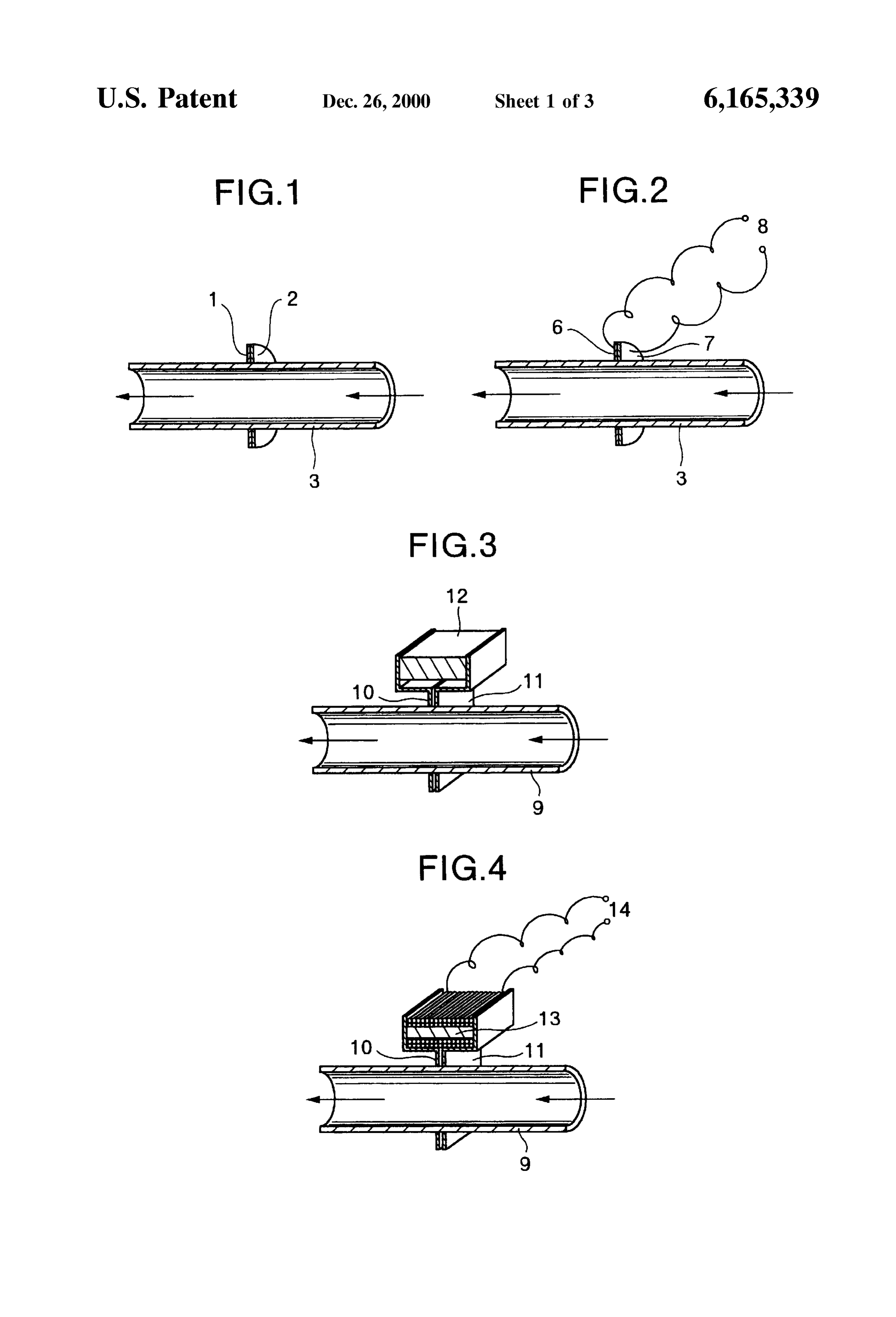
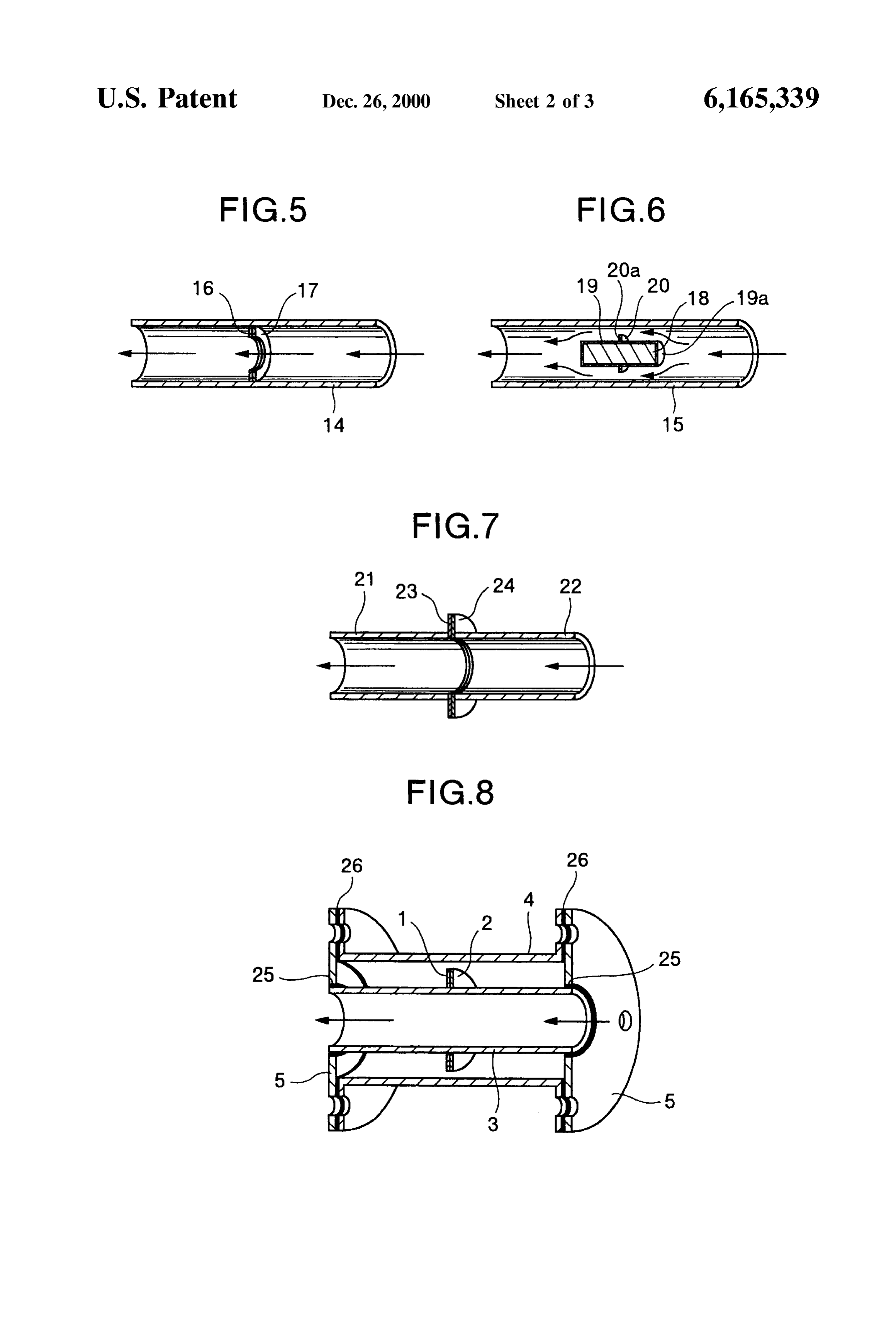
The fact of being able to use large diameter pipe and thick applying narrow magnetic fields encircling a pipeline liquid pipe wall may seem to be illogical according to average flow System according to a Second embodiment of the thinking and especially So when as mentioned previously the present invention, magnetic tape recording System was used to illustrate the FIG. 4 is a half-sectioned schematic perspective view function of the device and effect on the molecule clusters. showing a device and a method for treating a liquid by However in the case of pipe wall thickness and large pipe applying narrow magnetic fields encircling pipeline liquid diameter, there can be no comparison with magnetic tape. It flow System according to a modification of the Second is pointed out that the electrodes and magnetic pole pieces embodiment of the present invention, encircle the pipe OD or the pipe ID and the resulting field FIG. 5 is a half-sectioned schematic perspective view effect is completely different to that of the tape reproducing showing a device and a method for treating a liquid by or recording head which only contacts the narrow Strip of applying a narrow electric field within a pipeline liquid flow magnetic tape. Furthermore, it has been found from actual System according to a third embodiment of the present experimental results that the effect of the electric or mag invention, netic field when applied to the outer periphery of the plastic or non-magnetic pipe Section does indeed extend through the 15 showing FIG. 6 is a half-sectioned schematic perspective view pipe wall and produces an effect on the liquid contacting the applying anarrow device and a method for treating a liquid by magnetic fields within a pipeline liquid inside surface of the pipe. However the effect is not limited flow System according to a fourth embodiment of the present to the particular liquid contacting the pipe wall but the effect is transmitted throughout the liquid by a chain-like reaction. invention,
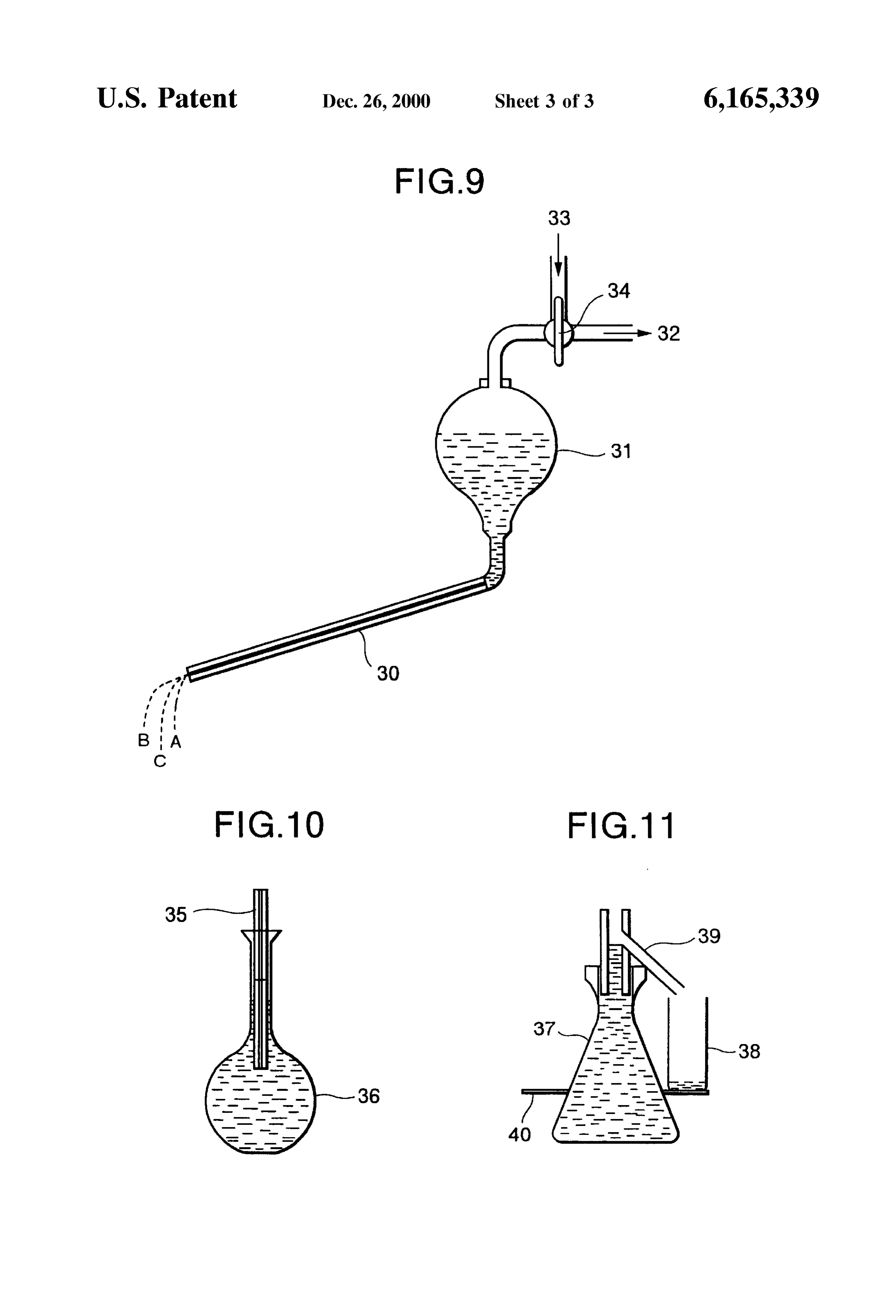
The size change of the cluster in close proximity to the pipe FIG. 7 is a half-sectioned schematic perspective view wall produces a change of electric charge which then effects showing a device and a method for treating a liquid by the next cluster. It is understood that those clusters in close applying a narrow electric field to a pipeline liquid flow proximity to the pipe wall will be most strongly effected, and System according to a fifth embodiment of the present to achieve a homogeneous condition recirculation of the invention, fluid through the device will provide increased distribution FIG. 8 is a half-sectioned schematic perspective view of the cluster size control. 25 more closely showing the construction of a unit employing In order to provide a clear understanding that the effect of the Self generating electric field electrodes according to the the very narrow electric field or magnetic field can be first embodiment of the present invention, transmitted through the thick walled piping, the following FIG. 9 is a schematic view of a test unit to illustrate Surge explanation is provided. effect in liquid flow due to cluster size, Firstly, we consider a plastic pipe with water flowing FIG. 10 is a schematic view of a device for weight through the pipe. It is well known that any form of friction measurement according to a test of the present invention, on the one Surface of a plastic pipe will cause an electroStatic and field to develop on the other surface of the pipe. If some FIG. 11 is a schematic view of a device used for volume form of distortion or disturbance is applied to the electro expansion measurement according to a test of the present Static field on the outer Surface of the plastic pipe, it will 35 invention.
Similarly be reflected back as a disturbance or distortion on the inside of the plastic pipe. This disturbance or distortion DETAILED DESCRIPTION OF THE on the inside of the plastic pipe is also reflected into the PREFERRED EMBODIMENTS water as an electroStatic effect on the water.
Referring to a first embodiment of the present invention
Similarly with the non magnetic pipe, whether it be metal 40 shown in FIG. 1, two electrodes comprising a positive or otherwise, an electroStatic field, or ionization, will be produced on the outer Surface of the pipe. An applied field electrode 1 and a negative electrode 2 are attached to and encircling the outer periphery of a plastic pipe 3. The causes a disturbance, or distortion, of the electrostatic field positive electrode 1 and negative electrode 2 have different which is reflected back into the water. As evidence that electroStatic fields do develop on a metal, the inventor 45 electrochemical potentials, for example a carbon positive directs attention to the book “The Ion Controversy' by Dr. electrode and an aluminum negative electrode. The carbon Charles Wallack. Dr. Wallack describes how a ship moving and aluminum electrodes are made from extremely thin through the water builds up a charge of the positive ion (a carbon and aluminum sheets, and placed directly in physical positive electrostatic charge). The effect of this positive ion contact or with a very thin film of electric insulation ther charge is reflected through the thick metal hull of the ship ebetween. The electrode Set is attached to, and encircle the into the inside, and appears as a reduced minus ion level (a 50 outer periphery of an electric insulating pipe 3 Such as a reduced negative electrostatic charge) within the ship's hull length of plastic pipe. A more detailed drawing of unit up to the waterline. Above the waterline the ionization is construction employing Such a set of electrodes is shown in unaffected. FIG. 8, in which 1 and 2 are the carbon and aluminum electrodes respectively. The electrodes 1 and 2 are attached
BRIEF DESCRIPTION OF THE DRAWINGS 55 to, and encircle the outer periphery of a plastic pipe 3. The FIG. 1 is a half-sectioned schematic perspective view assembly of electrodes 1 and 2 and the plastic pipe 3 is showing a device and a method for treating a liquid by enclosed in an outer body 4 and end face plates 5. The inner applying a narrow electric field encircling a pipeline liquid periphery of the face plates 5 is grooved to accept an O-ring flow System according to a first embodiment of the present 25 which forms a tight seal between the ends of the plastic invention, 60 pipe 3 and the end face plates 5. Seal packings 26 form a FIG. 2 is a half-sectioned Schematic perspective view tight seal between the end face plates 5 and the outer body showing a device and a method for treating a liquid by 4 to maintain a constant environment and moisture free applying a narrow electric field encircling a pipeline liquid condition around the electrode.
flow System according to a modification of the first embodi In FIG. 2, a similar system to that of FIG. 1 is adopted, ment of the present invention, 65 except that the electrodes 6 and 7 are energized from an FIG. 3 is a half-sectioned schematic perspective view external electric supply source 8. The electrodes 6 and 7 may showing a device and a method for treating a liquid by be made of any electro-conductive material, preferably both
Page 8
electrodes should be of the same material. A length of To explain the function of the devices of FIG. 1 and FIG. electric insulating pipe 3 is used to Support the electrode Set 8, attention is directed to the electric insulating pipe (plastic) 6 and 7. as 3 in FIG. 1, and FIG.8. It is commonly known that many In FIG. 3 a magnetic System is adopted instead of elec plastic materials have the effect of producing an electroStatic trodes in FIGS. 1 and 2, in which 9 is a section of non field when excited by some friction of the surface. Referring magnetic pipe with the magnetic pole pieces 10 and 11 water to water flowing through a plastic pipe, the friction of the flowing through Such a piece of plastic pipe produces encircling edgewise the periphery of the pipe 9 and with the an electrostatic magnetic pole pieces 10 and 11 being magnetically ener Surface of the plastic Voltage field which builds up on the outer gized by the magnet 12. pipe. This means that the outer Surface 1O of the plastic pipe is covered by an electrostatic field. The
In FIG. 4 the same System of a magnetic transverse electrodes of different electro-chemical potential, for assembly is adopted but employing an electro-magnetic example carbon and aluminum are contained within the System for energizing. The electro magnet 13 is powered by electroStatic field, and the electroStatic field is Seen as an an external electric Supply Source 14. electrolyte.
In the devices shown in FIG. 1 through FIG. 4, the narrow 15 To explain this further, an electrostatic field is an ionized energy field members are applied to, and encircle the exter form, either positive ion or negative ion. An electroStatic nal periphery of the Supporting pipe Section, while the field has a conductivity due to the ionization, which in effect narrow field members 16 and 17 are applied within the pipe is similar to liquids Such as water in which the Soluble section 14 in FIG. 5. In FIG. 5 the self generating electrodes content is ionized due to Solution, and therefore becomes 16 and 17 are situated within the electric insulation pipe electroconductive. All materials especially those which are Section 14 and directly contacted by the liquid. electrically conductive have an electron field Surrounding In FIG. 6 a permanent magnet System is situated within them. This may be likened to an electron gas. With two the pipe section 15 in which the permanent magnet 18 is members of different electrochemical potential Situated in applied with end covers 19 and 19a joining at the center to close proximity to each other in air and with Suitable form the pole pieces 20 and 20a. In the drawing the pole 25 equipment it is possible to measure a potential difference pieces 20 and 20a are shown at the center of the permanent between the two members. However due to the poor con magnet length. However, it will be apparent that the joining ductivity of the air, the potential developed is extremely of the end covers and forming the pole pieces 20 and 20a can weak. When these same two members are immersed in water be positioned at any point in the overall length of the in which the dissolved Salts cause relatively strong permanent magnet. conductivity, the potential difference between the members In the construction shown in FIG. 7, two separate pipe has more energy and can produce a relatively strong electric sections 21 and 22 are employed with the narrow field current flow.
producing members 23 and 24 being situated between the Carbon will absorb electrons; and aluminum will release Sections 21 and 22. In this embodiment the various Systems electrons. Therefore, in the vicinity of the carbon electrode may be employed; the Self generating electrodes having 35 there is a reduction of electrons and in the vicinity of the different electro-chemical potentials, the externally electri aluminum electrode there is an excess of electrons, this cally energized electrodes, the magnetic poles of a perma provides a potential difference between the carbon electrode nent magnet or electro-magnet. For convenience only the and the aluminum electrode, with a resulting electric poten illustration of the Self generating electrodes having different tial being present in the narrow gap between the electrodes. electro-chemical potentials is shown with the electrodes 23 40 Other combinations of electro-conductive materials having and 24. It will be obvious in view of FIG. 1, FIG. 2, FIG. 3 different electro-chemical potentials will also show a poten and FIG. 4 that the electrodes and pole pieces illustrated in tial difference due to the effect of a difference in the these figures could be inserted between two pipe Sections as efficiency to release electrons, in which a low electron illustrated in FIG. 7. Although the description of the struc release material will become positively polarized as related ture of the device of this invention is based on only one set 45 to a high electron release material. Therefore, any electro of electrodes or one Set of magnetic pole pieces, it is pointed conductive materials with different electro-chemical poten out that any number of electrodes or pole pieces may be tials will show an electric potential difference when exposed used. It is further pointed out that with the Self generating to an electrostatic field.
electrode construction, other electrode Sets may be of dif In liquids which exhibit molecular clustering Such as ferent materials to those of the first electrode set. The 50 water, etc. the cluster formation is not constant. The molecu important factor is that there is the minimum Separation lar clusters are in a continual State of change, forming between electrodes or magnetic poles and Such separation clusters, breaking down, and reforming clusters. Also the allows a very narrow electric fields or magnetic field to be cluster size is a continually changing condition, Some mol produced. ecules forming large clusters and others forming Small To any one skilled in the art it will be obvious how there 55 clusters. The clustering build-up and change is a continuous is a magnetic field effect produced in the liquid flow either fluctuation. This continuous fluctuation of clustering and from a So called permanent magnet or an electro-magnetic cluster Size shows the very weak bonds which are the cause System. Furthermore, it can be clearly understood how of the clustering. There is insufficient bond strength to electro-conductive materials having different electro maintain a constant cluster Size and even temperature chemical potentials can provide a Voltaic cell Structure when 60 changes or movement of the liquid itself can have an contacted by an electrolyte, Such as water or other liquids, appreciable effect on the cluster condition; therefore, it can even those being only very weak electrolytes Such as Sauces, be easily Seen how a low level magnetic field or electric field whiskey, wine, etc. However, in the case of the externally can control the clustering effect.
applied electrodes having different electro-chemical poten As a molecular cluster which is large in relation to the tials where there is no contact with the liquid, as in the cases 65 narrow field passes through the narrow field, the energy, of FIG. 1, and FIG. 8, the system of electric energy gen electric or magnetic, causes a change of the weak molecular eration is Somewhat different. bonds and the cluster changes to a size which is relative to
Page 9
the width of the narrow field. A liquid which passes through perature to 75 C. and then maintained at that temperature to the narrow field only one time will have only portion of the allow evaporation of the two samples. This initial volume of molecular clusters reduced in Size, but Such treatment is each Sample was 100 cc and this was allowed to evaporate often Sufficient for a particular requirement. However, recir down to 50 cc, at which point Some precipitation of the culation of the liquid through the narrow field can provide dissolved content (solute) of the water had occurred. The highly efficient control of the cluster size. AS mentioned residual Samples were corrected to exactly the same Volume above, the clusters are in a constant State of change under (50 cc) by adding pure water, then allowing the samples to normal conditions. The application of a device according to Stand for a few hours in order for the exceSS precipitate to be this invention does stabilize the state of cluster formation. In redissolved. A measurement of electro-conductivity was the case of Sauces, whiskey, wine etc. the reduced cluster taken of each Sample which showed a considerably lower Size allows quick blending of the water content with the electro-conductivity for the not treated Sample than that of Sauce base, whiskey, wine, etc. and once the blending has the treated sample. A difference of 16 uS/cm has been measured between the not treated water and the water formed it does not again Separate. In other words the liquids treated by the device of this invention. An electro have been conditioned into Small clusters which are held
Stable by the blending. In the case of a conditioned liquid 15 conductivity measurement is the general indication of the amount of dissolved Salt content of the water Such as which is not blended with a second liquid, the controlled calcium Salts and magnesium Salts. With a reduced amount cluster Size will remain in Such condition for a relatively of salt in solution the electro-conductivity will be lower. In Short time and unless otherwise used in Some manner to take the above test the electro-conductivity measurements advantage of the cluster control, the clustering effect within showed a lower value for the not treated water than that of that liquid will gradually revert to the fluctuation of cluster the treated water, and this can be taken as showing reduced formation and cluster break down. content of the Soluble Salt in the not treated water, whereas Another effect of the molecular cluster size control is that the treated water showed a higher electro-conductivity than of increased ionization of the liquid and the delayed pre the not treated water thereby indicating a maintained high cipitation of dissolved content of the liquid. In the case of Salt content in the water due to reduced precipitation, which natural water with the dissolved content, (Solute) of calcium 25 as explained previously, is brought about by the change of Salts, magnesium Salts, etc., the action of reducing the electric charge with the change of the clusters to Smaller cluster Size allows a change of electric charge within the sizes. The change of electric charge is also a change of liquid which is a change of ionization of the liquid and ionization.
dissolved content. In this Sense, the device Structures of this Evidence of the function of the narrow and magnetic field invention may be used for water treatment to prevent Scaling control effect was further investigated with Specially devised (calcium and magnesium Scale, etc.) within a water contain tests. In one case, the water untreated was carefully degassed ment System. by vacuum then filtered through a 0.4 micron filter. A test rig In order to provide evidence of the effect of molecular of a Small reservoir connected to a length of 2.0 mm cluster control by the devices of this invention some tests capillary tube was set up. The water was drawn by vacuum were carried out. The device used had the narrow Spaced 35 through the capillary tube into the reservoir in order to field members attached to the outer periphery of a plastic eliminate the possibility of air being added to the water pipe with %" (12.7 mm) bore and wall thickness of 1.5 mm. through the turbulence and general disturbance which could The System used was that of electrode materials having occur by Simply pouring the water into the reservoir. When different electrochemical potentials as shown Schematically the reservoir was almost full, the water was allowed to flow in FIG. 1 and a similar construction to that shown in FIG. 8. 40 out through the capillary tube. It was observed that instead In this case, Segmented carbon and aluminum electrodes of a smooth flow of water leaving the open end of the were used to encircle the pipe. In View of the various capillary tube, that there was a very irregular flow with the possibilities of construction to have the electrode assembly water flow being fast at times and slow at other times. This or magnetic pole encircling the OD or ID of the pipe, we was easily observed by the variations in visible extension of would refer to these structures combined as annular 45 the water flow from the capillary tube. It appeared to Spurt members, e.g. the Segmented carbon and aluminum out then slow down.
electrode, and the one piece electrodes are referred to as Some of the same water was passed through a device annular members. The carbon and aluminum elements were prepared with the construction then filtered and degassed as in direct physical contact (no separator was used between before. The same procedure was used to fill the small the electrodes). Also to make the electrode assembly more 50 reservoir, then the water was allowed to flow through the rigid the electrode Set was Supported by members of a more capillary tube. This time the water flow from the open end rigid insulative material. The combined thickness of the of the capillary tube was completely Smooth and had no electrode assembly and Supporting members was 0.25 mm, irregular spurting action.
with the actual thickness of the carbon and aluminum From this test it was assumed that the molecule cluster electrode combination being 0.01 mm. Size in the water had been reduced, thereby allowing a
Test of Delayed Precipitation (Anti-scaling) smooth flow through the capillary tube. To verify this the 2.0 The basic method of comparison between a treated mm bore capillary tube was replaced with a 0.5 mm bore Sample of liquid and a not treated Sample from experience capillary tube, and the test repeated using the treated water. appears to be the most reliable and is also applied in this test. With this reduced size bore the water flow again became Two sample volumes of water were taken from the one 60 irregular in a similar manner to that of the untreated water Storage tank. The one Volume remained untreated whereas through a 2.0 mm bore capillary tube. It appears obvious that the other Volume was allowed to pass one time through a the cluster Size of the untreated water was variable to Size in device of this invention. An exactly measured amount of excess of 2.0 mm whereas the treated water showed the each Sample volume (not treated and treated) was placed in variable cluster size to be only in excess of 0.5 mm due to identical glass beakers, then placed over a heating device to 65 the effect of the device with narrow field construction. Simultaneously heat the Samples equally and allow evapo An example of the device used for this test is shown in ration of the water. The two Samples were raised in tem FIG. 9 in which 30 is the capillary tube, 31 the reservoir, 32
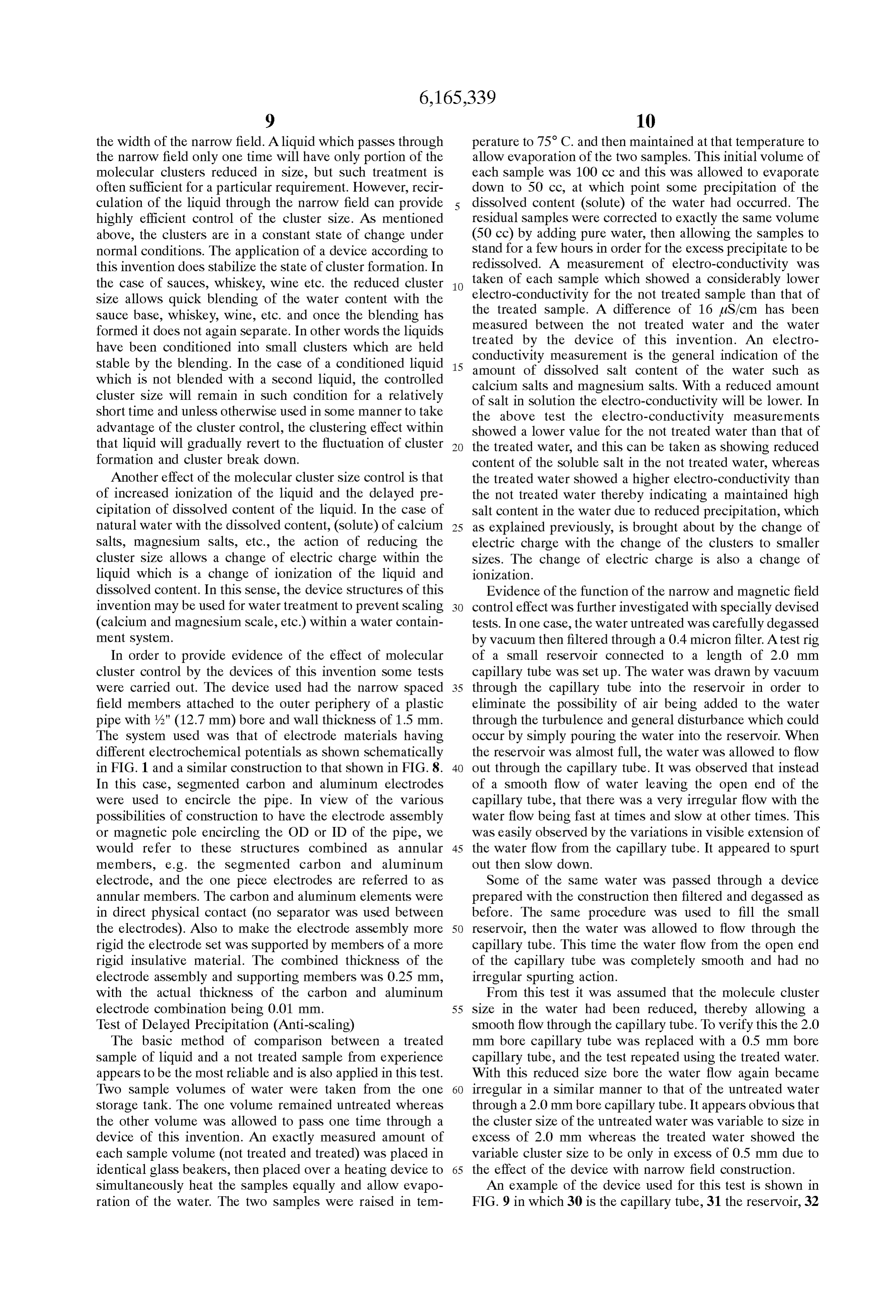
Page 10
air out line to vacuum pump, 33 air in, and 34 a 3 way valve field according to this invention exhibits an effect Similar to to Switch from air out to air in. Letters A, B and C show the the thermal effect on water.
liquid flow from the capillary tube orifice in which A and B An example of the device used for this test is shown FIG. show the Sudden flow Surge for untreated liquid and C shows 11 in which 37 is the container, 38 the collecting cup, 39 the the Steady flow for liquid treated by the device according to overflow pipe, and 40 a circular plate Surrounding the FIG. 1 and FIG. 8 of the invention. container 37 to support the collecting cup 38. The container This finding brought up two possibilities: was filled with liquid up to the overflow point for both the 1) the number of molecules in the cluster was reduced; or untreated liquid and the liquid treated by the device of this 2) the number of molecules in the cluster remained the same invention, then the device filled with liquid was heated in a but with tighter bonding to condense the cluster. water bath.
A further test was made to verify which of the above two Test No. 3 confirms the result of test No. 2 and both tests possibilities had occurred. No. 2 and No. 3 confirm test No. 1.
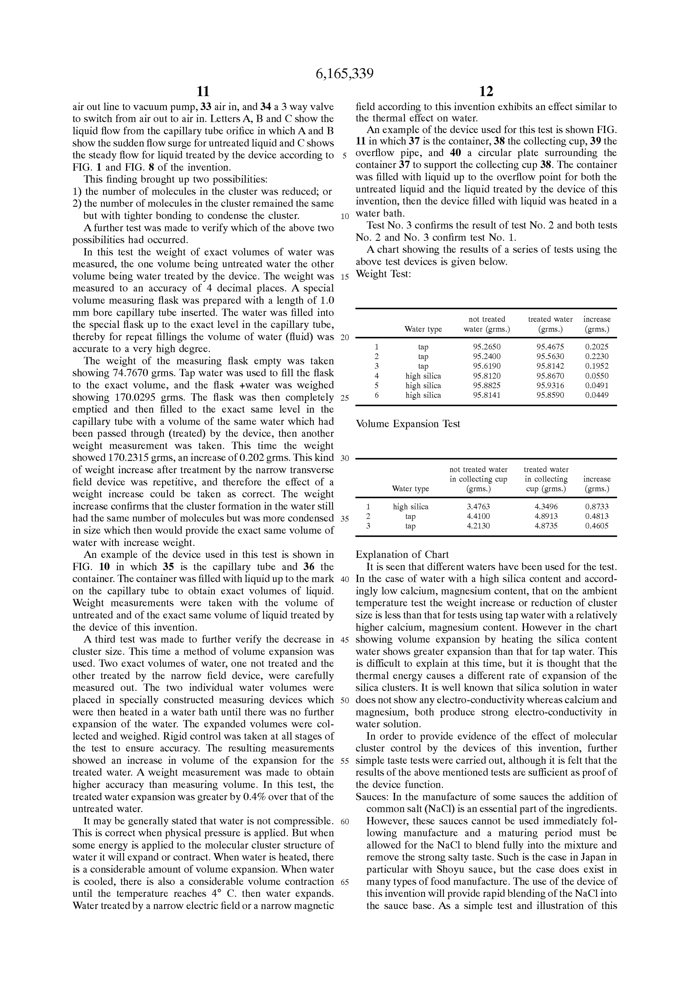
In this test the weight of exact volumes of water was A chart showing the results of a Series of tests using the measured, the one volume being untreated water the other above test devices is given below.
volume being water treated by the device. The weight was 15 Weight Test:
measured to an accuracy of 4 decimal places. A special
Volume measuring flask was prepared with a length of 1.0 mm bore capillary tube inserted. The water was filled into not treated treated water increase the Special flask up to the exact level in the capillary tube, Water type water (grims.) (grims.) (grims.) thereby for repeat fillings the volume of water (fluid) was 1. tap 95.2650 95.4675 O.2O25 accurate to a very high degree. 2 tap 95.24OO 95.563O O.223O The weight of the measuring flask empty was taken 3 tap 95.6190 95.8142 O.1952 showing 74.7670 grims. Tap water was used to fill the flask 4 high silica 95.812O 95.8670 0.0550 to the exact volume, and the flask +water was weighed 5 high silica 95.8825 95.9316 O.O491 showing 170.0295 grims. The flask was then completely 25 6 high silica 95.8141 95.8590 O.O449 emptied and then filled to the exact same level in the capillary tube with a volume of the same water which had Volume Expansion Test been passed through (treated) by the device, then another weight measurement was taken. This time the weight showed 170.2315 grms, an increase of 0.202 grims. This kind of weight increase after treatment by the narrow transverse not treated water in collecting cup treated water in collecting increase field device was repetitive, and therefore the effect of a Water type (grms.) Cup (grims.) (grims.) weight increase could be taken as correct. The weight increase confirms that the cluster formation in the water Still 1. high silica 3.4763 4.3496 O8733 had the same number of molecules but was more condensed 35 2 tap 4.4100 4.8913 O4813 3 tap 4.2130 4.8735 O4605 in size which then would provide the exact same volume of water with increase weight.
An example of the device used in this test is shown in Explanation of Chart
FIG. 10 in which 35 is the capillary tube and 36 the It is seen that different waters have been used for the test. container. The container was filled with liquid up to the mark 40 In the case of water with a high Silica content and accord on the capillary tube to obtain exact volumes of liquid. ingly low calcium, magnesium content, that on the ambient Weight measurements were taken with the volume of temperature test the weight increase or reduction of cluster untreated and of the exact same Volume of liquid treated by Size is less than that for tests using tap water with a relatively the device of this invention. higher calcium, magnesium content. However in the chart A third test was made to further verify the decrease in 45 showing Volume expansion by heating the Silica content cluster size. This time a method of Volume expansion was water shows greater expansion than that for tap water. This used. Two exact volumes of water, one not treated and the is difficult to explain at this time, but it is thought that the other treated by the narrow field device, were carefully thermal energy causes a different rate of expansion of the measured out. The two individual water volumes were Silica clusters. It is well known that Silica Solution in water placed in Specially constructed measuring devices which 50 does not show any electro-conductivity whereas calcium and were then heated in a water bath until there was no further magnesium, both produce Strong electro-conductivity in expansion of the water. The expanded Volumes were col water Solution.
lected and weighed. Rigid control was taken at all Stages of In order to provide evidence of the effect of molecular the test to ensure accuracy. The resulting measurements cluster control by the devices of this invention, further showed an increase in Volume of the expansion for the 55 Simple taste tests were carried out, although it is felt that the treated water. A weight measurement was made to obtain results of the above mentioned tests are Sufficient as proof of higher accuracy than measuring Volume. In this test, the the device function.
treated water expansion was greater by 0.4% over that of the Sauces: In the manufacture of Some Sauces the addition of untreated water. common Salt (NaCl) is an essential part of the ingredients. It may be generally Stated that water is not compressible. 60 However, these Sauces cannot be used immediately fol This is correct when physical pressure is applied. But when lowing manufacture and a maturing period must be Some energy is applied to the molecular cluster Structure of allowed for the NaCl to blend fully into the mixture and water it will expand or contract. When water is heated, there remove the Strong Salty taste. Such is the case in Japan in is a considerable amount of Volume expansion. When water particular with Shoyu Sauce, but the case does exist in is cooled, there is also a considerable Volume contraction 65 many types of food manufacture. The use of the device of until the temperature reaches 4 C. then water expands. this invention will provide rapid blending of the NaClinto Water treated by a narrow electric field or a narrow magnetic the Sauce base. As a simple test and illustration of this
Page 11
effect, a small quantity of NaCl is dissolved in water until water until they could Sense a mild Salty taste, then compare the Salty taste is apparent. The Volume of Salted water is this with the same Salted water after being passed through Separated into two volumes. The one volume is passed the device. In this way the degree of SaltineSS in the water through a device of this invention, the other Volume was Set to the taster's own Standard which then made it clear remains untreated. A simple taste test will show that the to that taster that there was indeed a taste change due to the salty taste of the treated volume of salted water has effect of the device.
completely disappeared whereas the untreated Volume of Although the present invention has been described with salted water still retains the salty taste. This very effec reference to preferred embodiments thereof, many modifi tively illustrates the rapid change of molecular cluster Size cations and alterations may be made within the Spirit of the to allow a blending of two components of a mixture. present invention.
What is claimed is:
Wines. It is common knowledge and an essential part of 1. An apparatus for use in controlling molecular clusters wine manufacturing, to allow a maturing period for the in a liquid, Said apparatus comprising: full taste of the wine to develop. This means that the a pipe through which the liquid is to flow in a flow manufactured base wine must be allowed to Stand over a direction, and period of time for maturing to occur. AS in the case of 15 an energy applying device comprising two electrodes or Sauces etc. a tasting method can be used to show the two magnetic pole pieces provided along a periphery of obvious difference in the wine before treatment and after treatment with the device of this invention. To make this
Said pipe in a direction transverse to the liquid flow direction operable to apply one of an electric and a test, a very cheap wine with an obvious acidic taste was magnetic energy field to the liquid transversely to the used. Two volumes were taken from the same bottle of flow direction, wine. The one Volume remained untreated, whereas the wherein the two electrodes or two magnetic pole pieces other Volume was passed through a device of this inven are Spaced apart by less than 1 millimeter, and the tion. The comparison tasting of the not treated portion and Overall thickness of Said energy field applying device is the treated portion showed a very obvious reduction of the less than 10 millimeters in a direction parallel to the acidic taste of the wine after treatment with the device. 25 flow direction.
The wine taste had become mellow as would be the case 2. An apparatus for use in controlling molecular clusters with a matured wine. The maturing of wines etc. is again in a liquid as claimed in claim 1, wherein Said energy the result of cluster size reduction to allow blending of the applying device comprises at least two electrodes and Said components of the basic wine. The normal process is to pipe is made of electrically non-conductive material. allow time for the slow break down of the molecular 3. An apparatus for use in controlling molecular clusters clusters and ultimate close blending of the components. in a liquid as claimed in claim 2, wherein Said energy The above test allowing only one pass through a device of applying device is provided on an Outer peripheral Surface of this invention showed immediate improved blending or Said pipe.
maturing effect. A recirculation procedure with the wine 4. An apparatus for use in controlling molecular clusters passing through the device a number of times will provide 35 in a liquid as claimed in claim 2, wherein Said energy even more complete blending and mellowing of the wine. applying device is provided internally of Said pipe. Whiskey: In the case of whiskey, the effect of treatment by 5. An apparatus for use in controlling molecular clusters the device of this invention is not So rapid and recircu in a liquid as claimed in claim 2, wherein Said pipe is divided lation over a period of a few days is necessary to achieve at least into two pipe Sections and Said energy applying the desired maturing Stage. Again a test Sample of a very 40 device is provided between Said pipe Sections with an inner cheap, not matured whiskey was obtained. A Sample peripheral Surface of Said energy applying device exposed to Volume of this was placed in a recirculation device an interior of Said pipe.
including a device of this invention in the recirculating 6. An apparatus for use in controlling molecular clusters System. The recirculation was allowed to run continu in a liquid as claimed in claim 2, wherein Said at least two ously and taste checks were made on a daily basis. The 45 electrodes have different electrochemical potentials to pro whiskey taste was obviously changed from day to day. vide a Self generating electric field.
After a 12 day test period, the raw whiskey taste had 7. An apparatus for use in controlling molecular clusters changed towards that of a well matured whiskey. in a liquid as claimed in claim 6, wherein one of Said It is pointed out that to one skilled in the art of tasting electrodes is carbon and the other of Said electrodes is wine or whiskey the above mentioned changes would be 50 aluminum.
extremely obvious, especially with the “before and after 8. An apparatus for use in controlling molecular clusters tasting as explained. The taste of a raw whiskey and a well in a liquid as claimed in claim 2, for use with an external matured whiskey leaves no doubt in the mind of one skilled electric Supply Source, wherein Said at least two electrodes in the art. Similarly with wine. The connoisseur is able to are energized from the external electric Supply Source. detect by taste the difference between a wine which is 55 9. An apparatus for use in controlling molecular clusters matured and one that is still raw. Even those unskilled in the in a liquid as claimed in claim 1, wherein Said energy art of wine tasting can easily detect the differences between applying device comprises at least two magnetic pole pieces the original raw wine (poor quality) and the mellowness of and Said pipe is made of non-magnetic material. the wine after treatment with the device of this invention. 10. An apparatus for use in controlling molecular clusters This is evidenced by the fact that the taste testing was 60 in a liquid as claimed in claim 9, wherein Said energy applied with various people but unfortunately these were not applying device is provided on an Outer peripheral Surface of connoisseurs of whiskey or wine. However, the opinion in Said pipe.
each cases was the same, that of a more pleasant and Smooth 11. An apparatus for use in controlling molecular clusters taste. Similarly with the salt water test, each individual who in a liquid as claimed in claim 9, wherein Said energy was asked to taste the treated Salty water agreed that the Salty 65 applying device is provided internally of Said pipe. taste was not evident in the treated water. In the case of the 12. An apparatus for use in controlling molecular clusters Salt water test, each perSon was asked to add the Salt to the in a liquid as claimed in claim 9, wherein Said pipe is divided
Page 12
at least into two pipe Sections and Said energy applying 20. A method for use in controlling molecular clusters in device is provided between Said pipe Sections with an inner a liquid as claimed in claim 17, wherein the energy applying peripheral Surface of Said energy applying device exposed to members comprise two electrodes to be energized by an an interior of Said pipe. external electric Supply Source. 13. An apparatus for use in controlling molecular clusters 5 21. A method for use in controlling molecular clusters in in a liquid as claimed in claim 9, further comprising a a liquid as claimed in claim 20, wherein the energy applying permanent magnet, wherein Said at least two magnetic pole members are spaced apart by an insulating film therebe pieces are energized by Said permanent magnet. tWeen.
14. An apparatus for use in controlling molecular clusters 22. A method for use in controlling molecular clusters in in a liquid as claimed in claim 9, further comprising an a liquid electro-magnetic device, wherein Said at least two magnetic membersasare claimed in claim 17, wherein the energy applying magnetic pole pieces and are energized by a pole pieces are energized by Said electro-magnetic device.
15. An apparatus for use in controlling molecular clusters permanent magnet.
in a liquid as claimed in claim 1, wherein Said energy a liquid 23. A method for use in controlling molecular clusters in applying device is at least two electrode members edgewise 15 membersas are claimed in claim 22, wherein the energy applying spaced apart by an insulating film therebe encircling Said pipe and Spaced apart by an electrically tWeen.
insulating film interposed therebetween.
16. An apparatus for use in controlling molecular clusters 24. A method for use in controlling molecular clusters in in a liquid as claimed in claim 1, wherein Said energy a liquid as claimed in claim 22, wherein the energy applying applying device is at least two electrode members edgewise members are in direct physical contact with each other. encircling Said pipe. 25. A method for use in controlling molecular clusters in a liquid as claimed in claim 22, wherein Said magnetic pole 17. A method for use in controlling molecular clusters in pieces a liquid, Said method comprising: are spaced apart by a non-magnetic medium. producing an energy field with at least two energy apply a liquid asmethod 26. A for use in controlling molecular clusters in ing members comprising two electrodes or two mag members comprise intwo 25 claimed claim 17, wherein the energy applying magnetic pole pieces energized by netic pole pieces provided along a periphery of a pipe an electromagnetic device.
in a direction transverse to a liquid flow direction; and 27. A method for use in controlling molecular clusters in flowing the liquid transversely through the energy field, a liquid as claimed in claim 26, wherein the energy applying wherein the at least two energy applying members are members are spaced apart by an insulating film therebe Spaced apart less than 1 mm. tWeen.
18. A method for use in controlling molecular clusters in 28. A method for use in controlling molecular clusters in a liquid as claimed in claim 17, wherein the energy applying a liquid as claimed in claim 26, wherein the energy applying members comprise two electrodes having different electro members are in direct physical contact with each other. chemical potentials than each other for Self energizing. 35 29. A method for use in controlling molecular clusters in 19. A method for use in controlling molecular clusters in a liquid as claimed in claim 26, wherein Said magnetic pole a liquid as claimed in claim 18, wherein the energy applying pieces are spaced apart by a non-magnetic medium. members are spaced apart by an insulating film therebe tWeen. k k k k k
Provenance
- Collection
- Cited prior art
- Original PDF
- patentimages.storage.googleapis.com →
- Filed
- 1996-11-07
- Pages
- 12
- Method
- pdftotext (the PDF's own text layer) + pdftoppm 300dpi page scans
- Source
- Google Patents bibliographic record
- Granted
- 2000-12-26
- Inventors
- Jack Kenneth Ibbott
- Transcribed from
- patentimages.storage.googleapis.com →