patent · US4881593
Heat conducting device
21 November 1989
Page 1 — bibliographic record
United States Patent (19) 11) Patent Number: 4,881,593 Okayasu 45) Date of Patent: Nov. 21, 1989 54 HEAT CONDUCTING DEVICE 122171 8/1987 Japan.
76 Inventor: Kenji Okayasu, 20-15, Mukai-machi, OTHER PUBLICATIONS Gyoda-shi, Saitama-ken, 361, Japan 21 Appl. No.: 288,611 Technology Review, Diagram: Omnigraphics, 88-6
22 Filed: Dec. 22, 1988 Japan Mechanic Association Magazine, vol. 90, No. (30) Foreign Application Priority Data 824, p. 79.
Dec. 22, 1987 JP Japan ................................ 62-324819 Primary Examiner-Albert W. Davis, Jr. 51 int. Cl'.............................................. F28D 15/OO Attorney, Agent, or Firm-Cushman, Darby & Cushman 52 U.S. C. ................................. 165/104.29; 165/10; 57 ABSTRACT
58 Field of Search ................ 165/10, 104.31, 104.29, A heat conducting device having dream pipes for spa 165/104.22; 417/208,209 tially transporting heat without circulation of liquid by (56) References Cited repeating heat accumulation and radiation in a bound ary layers formed on wall surfaces of flow passages by
3,929,305 11/1975 Sabol .............................. 65/104.29 tion applied thereto comprising a flow passage or a 4,120,172 10/1978 Pierce ............................. 165/104.29 chamber including a heat drive pump arranged to be 4,212,593 7/1980 Chadwick........................... 417/209 operated by growth and contraction of steam bubbles in 4,450,690 5/1984 Clark, Jr. ...... ... 165/04.22 which each end of the dream pipes is opened, wherein 4,590,993 5/1986 Kurzweg........................ 165/104.31 a power for forward and rearward moving the liquid in 4,625,790 12/1986 Okayasu ......................... 165/104.29 the dream pipes depends upon the heat drive pump and 4,792,283 12/1988 Okayasu .............................. 417/209 another end of each of the dream pipes is designed to be
FOREIGN PATENT DOCUMENTS telescopic.
122170 8/1987 Japan. 2 Claims, 2 Drawing Sheets
s- asis | -si-
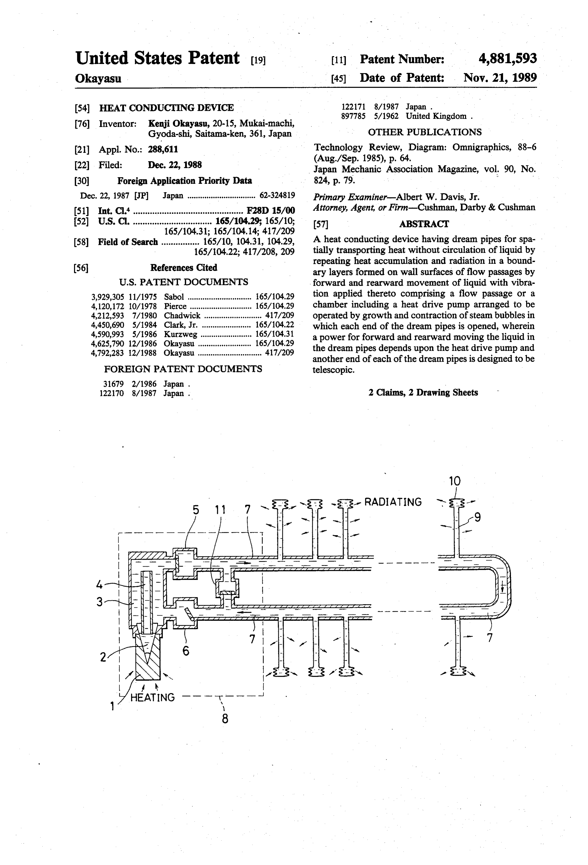
RADIATING is ---- - - - - -- - -am- are \ | || --
Q 7 N 1 2 NS 6 |1 || || -NM -3s- 3's Yss
Page 2
Drawing sheet — no readable text.
Page 3
Drawing sheet — no readable text.
Page 4
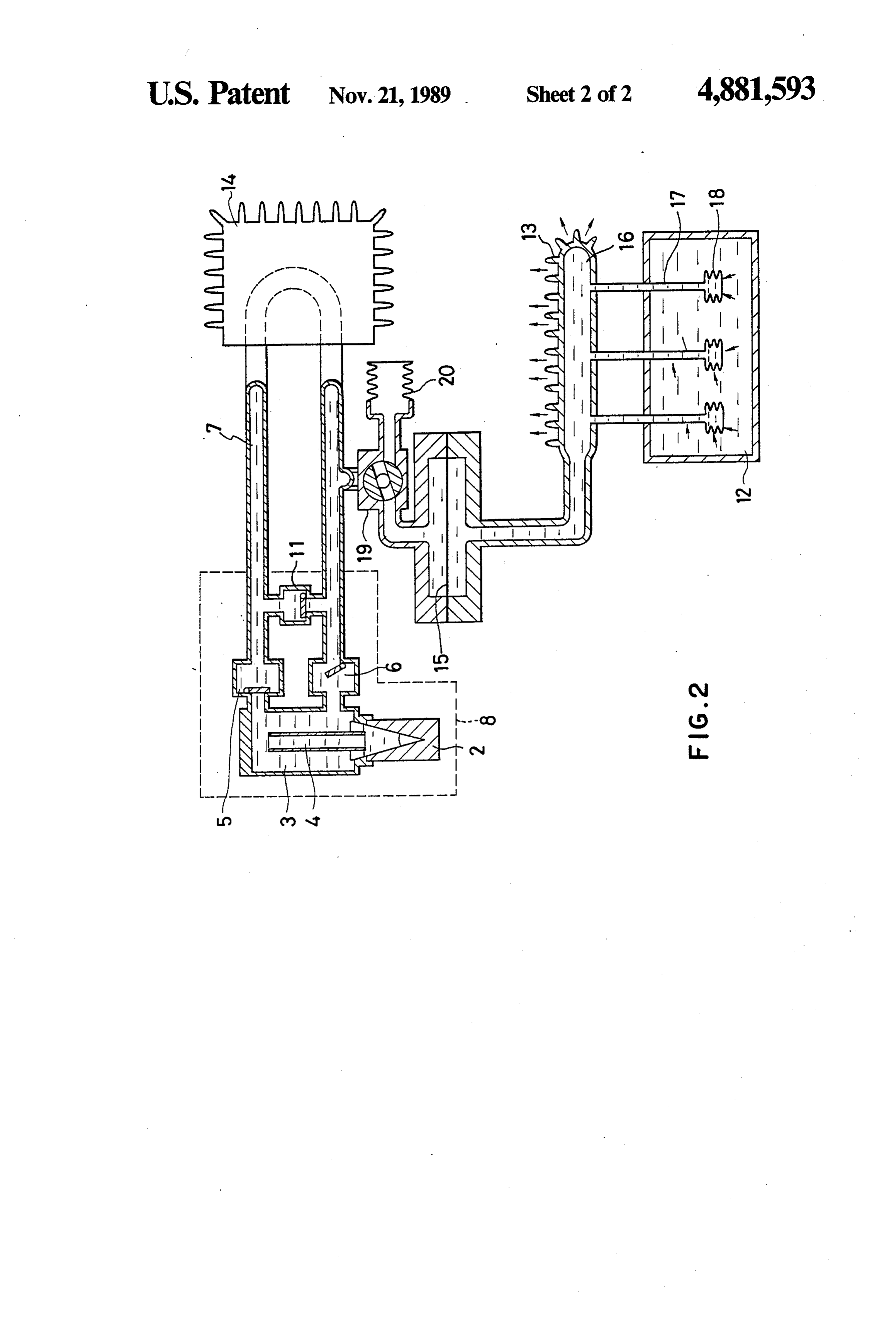
FIG. 2 is a schematic cross-sectional view of a heat
HEAT CONDUCTING DEVICE conducting device according to another embodiment of the present invention.
BACKGROUND OF THE INVENTION
DESCRIPTION OF THE PREFERRED
1. Field of the Invention EMBODIMENTS
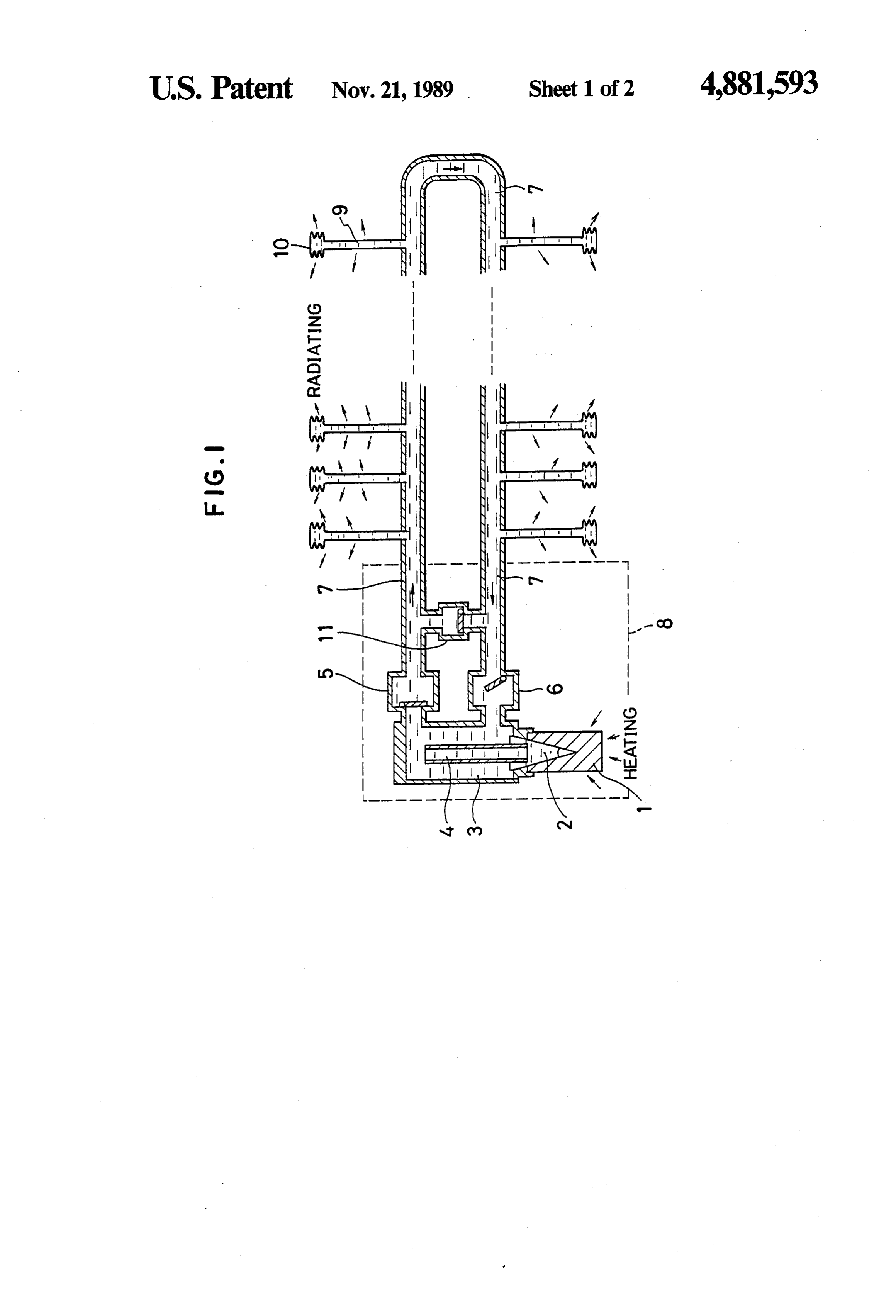
The present invention relates to a heat conducting FIG. 1 illustrates an embodiment of the present in device which can conveiently be used for cooling or vention, wherein a heat conducting device is used as a heating the portions in which a heat pipe cannot be heating device. The portion surrounded by a dashed utilized sufficiently, such as small portions of electronic 10 line serves as a heat drive pump 8, this heat drive pump circuits or precision mechanical equipments or soft 8 being provided with a heating portion 1 which in articles such as hot carpets or warm cloths. cludes a cavity portion 2 so that heat delivered by a heat 2. Description of the Prior Art source in the heating potion 1 is absorbed and thereby In order to achieve the above-described object, steam bubbles are generated in the cavity portion 2 "Dream Pipe' has been invented by Ulrich, Kurzweg, 15 disposed as disclosed at U.S. Pat. No. 4,590,993 granted May 27, generated inside bubbles the heating portion 1. The thus grow and reach a condensing pipe 4 1986, at P. 64, 88-6 (Aug/Sept.), 1985, "Technology disposed in a gas-liquid converter chamber 3, wherein Review, Diagram: Omnigraphics” and also at P. 79, No. the bubbles are immediately cooled down, condensed, 824, Vol 90, Japan Mechanic Association Magazine.
The above-described "Dream Pipe' is characterized 20 valve 5 and a suction stop valve since and disappears. At this time, 6 are a discharge stop each connected to by that heat can be kinetically conducted through a pipe the gas-liquid converting chamber 3, the heated liquid is by using a boundary layer formed on the wall of a pipe discharged to an outer pipe 7, while the cooled liquid by forward or rearward moving the liquid in the pipe introduced from the outer pipe 7, via the suction stopis with vibration applied to the pipe. The pipes of the type described above can exhibit advantages, with respect to 25 valve 6, into the gas-liquid converting chamber 3. Thus, the heat drive pump 8 circulates the liquid heat pipes, that the operating temperature can be se through lected optionally, only a low pressure needs to operate absorbed the by outer pipe 7, and as well supplies heat, the heating portion 1 thereof, to the outer such pipes, the operation start and stop can be freely pipe 7. A multiplicity of dream pipes 9 having an conducted, both wick device and the vacuum operation opened end thereof are secured to the thus-formed are not necessary, the structure is simple, and thereby 30 outer pipe 7, the dream pipes 9 each having a small such pipes can be easily manufactured. sized diaphragm type accumulator 10. By virtue of the However, the "Dream Pipe' cannot be operated only pressure change caused from growth and disappearance by a temperature difference, the temperature difference of the air bubbles in the heat drive pump 8, the liquid in though being sufficient to operate the heat pipes. There the dream pipes 9 is forward and rearward moved with fore, an outside power for applying vibration to the 35 vibration applied thereto. As a result of such forward liquid such as an electric motor or a compressor needs and rearward movement, boundary layers generated on to be provided. the pipe walls in the dream pipes 9 gradually conduct SUMMARY OF THE INVENTION the heat in the outer pipe 7 toward the diaphragm type accumulators 10 disposed at the front ends of the dream
An object of the present invention is to provide a heat 40- pipes 9 with heat supplied and received between the conducting device in which the characteristics of the boundary layers and the liquid which is being forward "Dream Pipe' cannot be deteriorated, and capable of being individually operated by only a temperature dif and rearward moved. Through these pipe walls, heat. can be delivered outside. An water hammer prevention ference, similarly to the heat pipes. stopper valve 11 is provided for the purpose of avoiding A heat conducting device having dream pipes ac 45 pressure rise due to inertia of the liquid in the outer pipe cording to the present invention for spatially transport 7 generated when the stopper valve of the heat drive ing heat without circulation of liquid by repeating heat pump 8 is operated. Although there is a variety of types accumulation and radiation in boundary layers formed of the heat drive pump, any one can be available only on wall surfaces of flow passages by forward and rear satisfying the required factor of pressure change. Alter ward movement of liquid with vibration applied thereto 50 natively, a structure may be employed in that a partial comprising a flow passage or a chamber including a portion of the outer pipe is expanded so as to be a cham heat drive pump arranged to be operated by growth and ber to which each end of the dream pipes is opened. contraction of steam bubbles in which each end of the Furthermore, the diaphragm type accumulators 10 may dream pipes is opened, wherein a power for forward be in the form of a bag made of rubber or soft plastic. and rearward moving the liquid in the dream pipes 55 The outer pipes 7 and the dream pipes 9 may be made of depends upon the heat drive pump and another end of flexible vinyl pipes or the like.
each of the dream pipes is designed to be telescopic. Referring to FIG. 1, arrows disposed below the heat A heat conducting device according to another em ing portion 1 designate the directions of the heat. Simi bodiment of the present invention is characterized in larly, arrows disposed around the dream pipes 9 and the that each end of the dream pipes is opened to another 60 accumulators 10 also designate the directions of heat flow passage or chamber which is connected, via a which has been radiated toward the outside thermal pressure conducting device, to the above-described load.
flow passage or chamber including the heat drive pump. FIG. 2 illustrates another embodiment of the present BRIEF DESCRIPTION OF THE DRAWINGS 65 invention in which the device according to the present invention is used as a cooling device that is character
FIG. 1 is a schematic cross-sectional view of a heat ized in that heat is removed from a thermal load 12 and conducting device according to the present invention; the thus-removed heat is arranged to be radiated outside and 12 by using a load radiating fin 13. Similarly to the
Page 5
former embodiment, the portion surrounded by a by repeating heat accumulation and radiation in a dashed line serves as a heat drive pump 8 which has a boundary layers formed on wall surfaces of flow pas heat source provided individually from the thermal sages by forward and rearward movement of liquid load. Since the outer pipe 7 passes through a pump with vibration applied thereto, said conducting device radiating device 14, heat from the heat drive pump 8 is comprising:
conducted to this pump radiating device 14 by the liq a flow passage or a chamber including a heat drive uid circulation. Therefore, only the pressure change in pump arranged to be operated by growth and con the heat drive pump 8 is conducted to a dream pipe traction of steam bubbles in which each end of said radiating chamber 15 via a diaphragm type pressure dream pipes is opened, wherein a power for for conducting device 15 connected to the outer pipe 7 at 10 ward and rearward moving said liquid in said the lower stream to the radiating device 14. Therefore, dream pipes depends upon said heat drive pump the dream pipes 17 connected to the dream pipe radiat and another end of each of said dream pipes is ing chamber 16 and diaphragm type accumulators 18 designed to be telescopic. thereof are operated. The dream pipes 17 and the dia 2. A heat conducting device having dream pipes for phragm type accumulator thereof are disposed in the 15 spatially transporting heat without circulation of liquid thermal load 12 so that heat in this thermal load 12 is by repeating heat accumulation and radiation in a conducted to the heat radiating chamber 16 from which boundary layers formed on wall surfaces of flow pas the heat is delivered by the radiating fin 13. A flow-rate sages by forward distribution valve 19 is disposed between the outer pipe with and rearward movement of liquid 7 and the diaphragm type pressure conducting device comprising:
20 vibration applied thereto, said conducting device 15 and is connected between them and is as well con nected to a sub-accumulator 20. By operating this flow a flow passage or a chamber connected, via a pressure rate distribution valve 19, flow rate upon the pressure conducting device, to another flow passage or change in the heat drive pump can be as needs distrib chamber including a heat drive pump arranged to uted between the diaphragm type pressure conducting 25 be operated by growth and contraction of steam device 15 and the sub-accumulator 20. Consequently, bubbles in which each end of said dream pipes is the operating force by the dream pipes can be con opened, wherein a power for forward and rear trolled for the purpose of controlling the amount of heat ward moving said liquid in said dream pipes de conducted through the dream pipes. pends upon said heat drive pump and another end What is claimed is: 30 of each of said dream pipes is designed to be tele 1. A heat conducting device having dream pipes for scopic.
spatially transporting heat without circulation of liquid k k
Provenance
- Collection
- Cited prior art
- Original PDF
- patentimages.storage.googleapis.com →
- Filed
- 1988-12-22
- Pages
- 5
- Method
- pdftotext (the PDF's own text layer) + pdftoppm 300dpi page scans
- Source
- Google Patents bibliographic record
- Granted
- 1989-11-21
- Inventors
- Kenji Okayasu
- Transcribed from
- patentimages.storage.googleapis.com →