patent · US4483324
Heat collecting and heat loss preventing apparatus
20 November 1984
Page 1 — bibliographic record
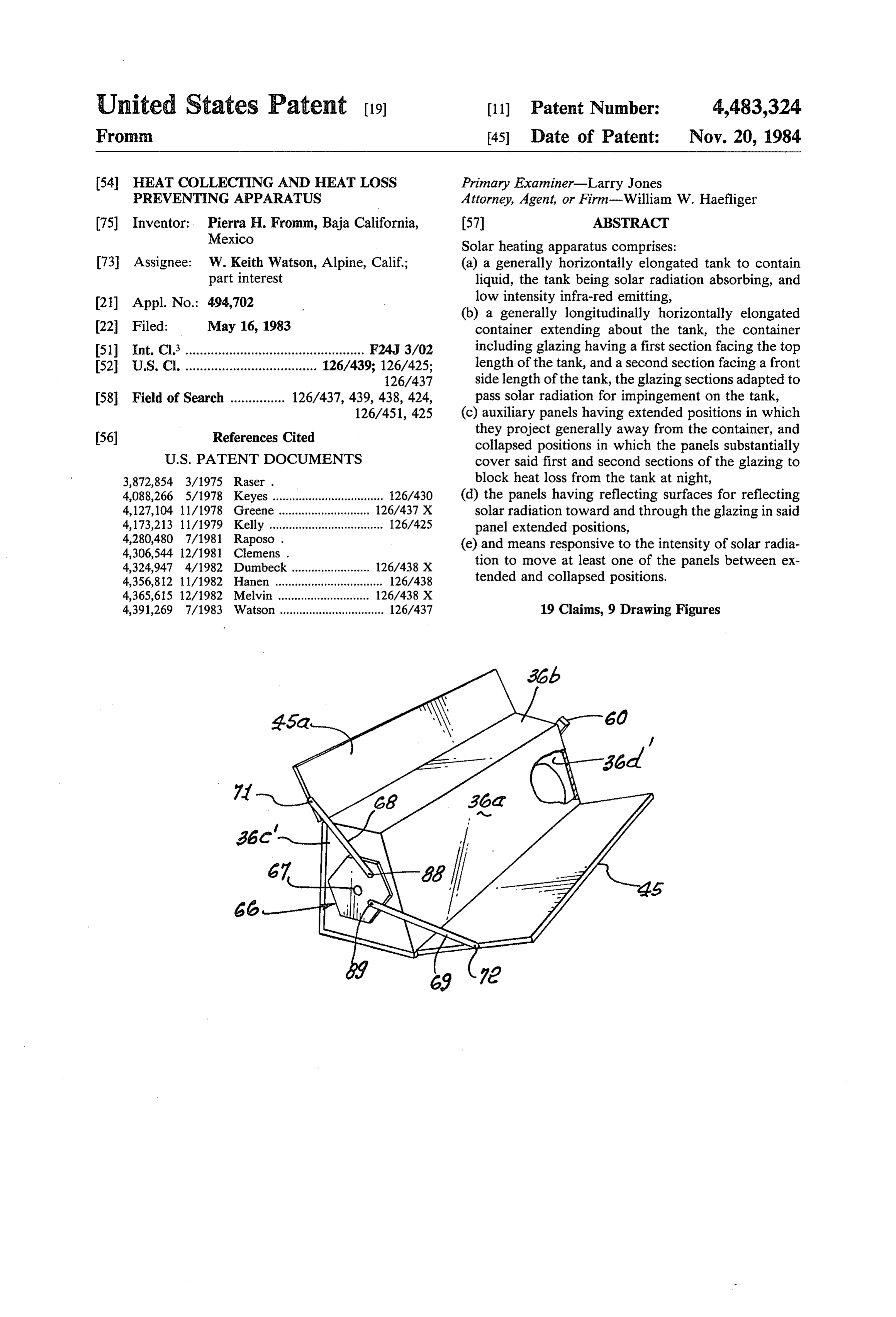
United States Patent (19) 11 Patent Number: 4,483,324 Fromm. (45) Date of Patent: Nov. 20, 1984 (54) HEAT COLLECTING AND HEAT LOSS Primary Examiner-Larry Jones PREVENTING APPARATUS Attorney, Agent, or Firm-William W. Haefliger 75) Inventor: Pierra H. Fromm, Baja California, 57 ABSTRACT Mexico Solar heating apparatus comprises:
73) Assignee: W. Keith Watson, Alpine, Calif.; (a) a generally horizontally elongated tank to contain part interest liquid, the tank being solar radiation absorbing, and 21 Appl. No.: 494,702 low intensity infra-red emitting, (b) a generally longitudinally horizontally elongated 22 Filed: May 16, 1983 container extending about the tank, the container 51) Int. Cl.................................................. F24J 3/02 including glazing having a first section facing the top 52 U.S.C. .................................... 126/439; 126/425; length of the tank, and a second section facing a front 126/437 side length of the tank, the glazing sections adapted to 58 Field of Search ............... 126/437, 439, 438, 424, pass solar radiation for impingement on the tank, 126/451, 425 (c) auxiliary panels having extended positions in which (56) References Cited they project generally away from the container, and collapsed positions in which the panels substantially
3,872,854 3/1975 Raser . block heat loss from the tank at night, 4,088,266 5/1978 Keyes .................................. 126/430 (d) the panels having reflecting surfaces for reflecting 4,127,104 11/1978 Greene .... ... 126/437 X Solar radiation toward and through the glazing in said 4,173,213 11/1979 Kelly ................................... 126/425 panel extended positions, 4,280,480 7/1981 Raposo. (e) and means responsive to the intensity of solar radia 4,306,544 12/1981 Clemens . tion to move at least one of the panels between ex
4,356,812 11/1982 Hanen ................................. 126/438 tended and collapsed positions. 4,365,615 12/1982 Melvin ..... 126/438 X 4,391,269 7/1983 Watson ................................ 126/437 19 Claims, 9 Drawing Figures
Page 2
Drawing sheet — no readable text.
Page 3
Drawing sheet — no readable text.
Page 4
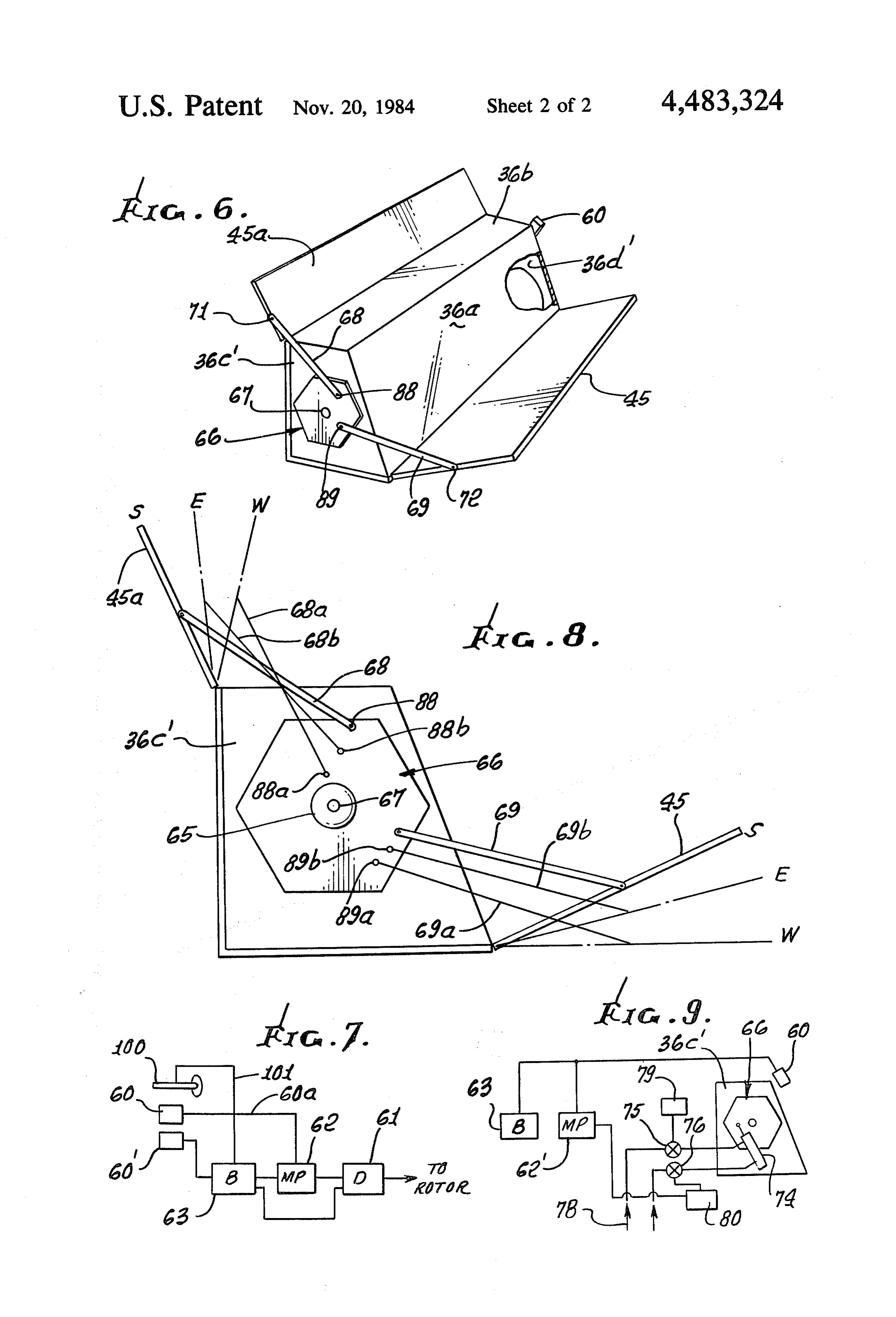
FIG. 6 is a view like FIG. 1, showing a modification;
HEAT COLLECTING AND HEAT LOSS FIG. 7 is a block diagram;
PREVENTING APPARATUS FIG. 8 is a diagrammatic end view of the FIG. 6 device; and
BACKGROUND OF THE INVENTION 5 FIG. 9 is a diagrammatic view of another modifica tion.
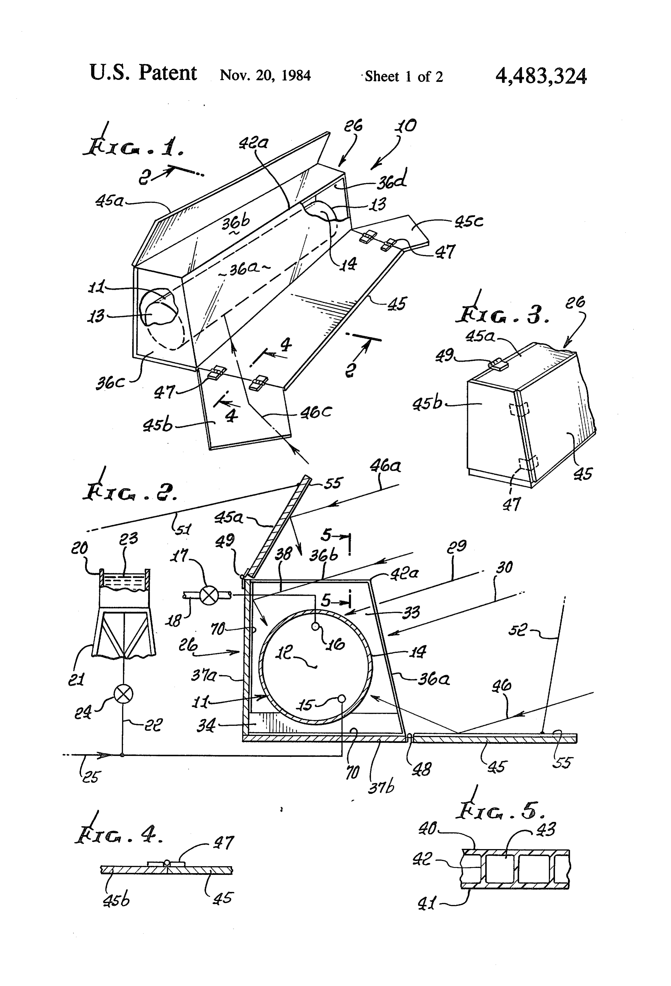
This invention relates generally to heat collecting and heat loss preventing apparatus; and more particularly DETAILED DESCRIPTION concerns a solar heater of high efficiency, and unusually In the drawings, the solar heater apparatus 10 in effective construction. 10 cludes a generally longitudinally horizontally elongated There is need in many areas of the world for water tank 11 to contain liquid, as for example water. The tank heaters that are simple, easy to use, efficient, and which may be metallic, and circular in cross section, with a will provide pressurized flow of heated liquid such as horizontal axis 12. It is shown to have end walls 13, and water. Prior designs of which I am aware do not meet a circular side wall 14, with a lower fill port 15 and a these objectives to provide the unusually advantageous 15 higher discharge port 16 in the opposite end walls. A combinations of features and modes of operation as are valve 17 in the discharge line 18 controls warm or hot found in the device of the present invention. liquid discharge, as required. The steel wall of the tank SUMMARY OF THE INVENTION may be treated with a nickel substrate chromium oxide coating compound such as MAXORB, a product of
It is a major object of the invention to provide appa 20 International Nickel Co., Birmingham, England. Such ratus meeting the above needs. Basically, the apparatus compounds allows high absorptivity of solar waves, and comprises: low emissivity of longer infra-red waves as at night, for (a) a generally horizontally elongated tank to contain heat loss suppression.
liquid, the tank being solar radiation absorbing, Liquid in the tank is typically pressurized and the (b) a generally longitudinally horizontally elongated 25 tank kept full, so that warm liquid will always flow container extending about the tank, the container in from the higher exit port 16. One such liquid pressuriza cluding glazing having a first section facing the top tion means is...shown in FIG. 2 to comprise a fill reser length of the tank, and a second section facing side voir 20 supported by structure 21 at a higher level than length of the tank, the glazing sections adapted to pass tank 11, a line 22 conducting liquid 23 from tank 20 to solar radiation for impingement on the tank, 30 tank 11 via control valve 24 and fill port 15. Liquid may (c) auxiliary panels having extended positions in be periodically filled into reservoir 20, whereby liquid which they project generally away from the container, in tank 11 is always pressurized, so that in remote re and collapsed positions in which panels substantially gions warm liquid (such as water) under pressurization, cover said sections of the glazing to blockheat loss from is always available. A pressurized source, indicated by the tank at night, and 35 line 25, may alternatively be used. (d) the panels having reflecting surfaces for reflecting A generally longitudinally extending, horizontally solar radiation toward and through the glazing in panel elongated container or housing such as is indicated at extended positions, 26, is employed to extend about or in association with (e) and means responsive to the intensity of solar the tank 11, the container defining glazing sections (pla radiation to move at least one of the panels between 40 nar, for ease of construction) 36a at the front of the extended and collapsed positions. container, 36b at the top of the container, 36c at one end As will appear, the container glazing may define flat of the container, and 36d at the opposite end. The glaz planar sections extending at angles relative to one an ing is adapted to receive impingement of solar radiation other; the panels may include first, second and third and to pass such radiation for direct impingement on the panels corresponding to glazing first, second and third 45 tank, i.e. at the top, front and opposite ends thereof. See sections; the glazing may include a fourth section, at the in this regard, solar rays 29 and 30 impinging as shown. opposite end of the tank, and there may be a fourth Air in space 33 between the tank and container is also panel to cover that glazing; the third and fourth panels heated and serves as an insulative barrier to block heat may be connected to the second panel to provide a conduction from the tank. The latter is supported at 34, compact assembly; and there may be adjustment con 50 as via wooden blocks or other means, so that barrier trols for the panels; also, an external reservoir for liquid space 33 extends through an angle sub-tending over (or line pressure) may be used to provide constant pres 180', about the tank.
surization of the tank liquid. The container typically includes rear wall 37a and These and other objects and advantages of the inven bottom wall 37b, the latter for example consisting of tion, as well as the details of an illustrative embodiment, 55 wood or synthetic resin (plastic) material. Urethane or will be more fully understood from the following speci isocyanurate foams are examples. Walls 37a and 37b are fication and drawings, in which: coated with or carry mirror-like reflecting material 70, such as aluminum foil or metallized plastic, to reflect
DRAWING DESCRIPTION solar rays as at 38 to the back side of the tank, and FIG. 1 is a perspective view of apparatus incorporat 60 infra-red waves back to the tank bottom. The glazing ing the invention; sections may advantageously consist of TWIN WALL FIG. 2 is an enlarged vertical section on lines 2-2 of TUFFAK 60, distributed by Rohm and Hass, or other FIG. 1; multiple glazed polycarbonate materials, with multiple FIG. 3 is a fragmentary perspective view showing walls and intermediate chambers. See FIG. 5 showing the heater glazing covered by panels; 65 parallel walls 40 and 41, integrally interconnected by FIG. 4 is an enlarged section on lines 4-4 of FIG. 1; ribs 42, with trapped air spaces appearing at 43. This and affords a very efficient additional means to block heat FIG. 5 is a section on lines 5-5 of FIG. 2; conduction and free convection in an outward direc
Page 5
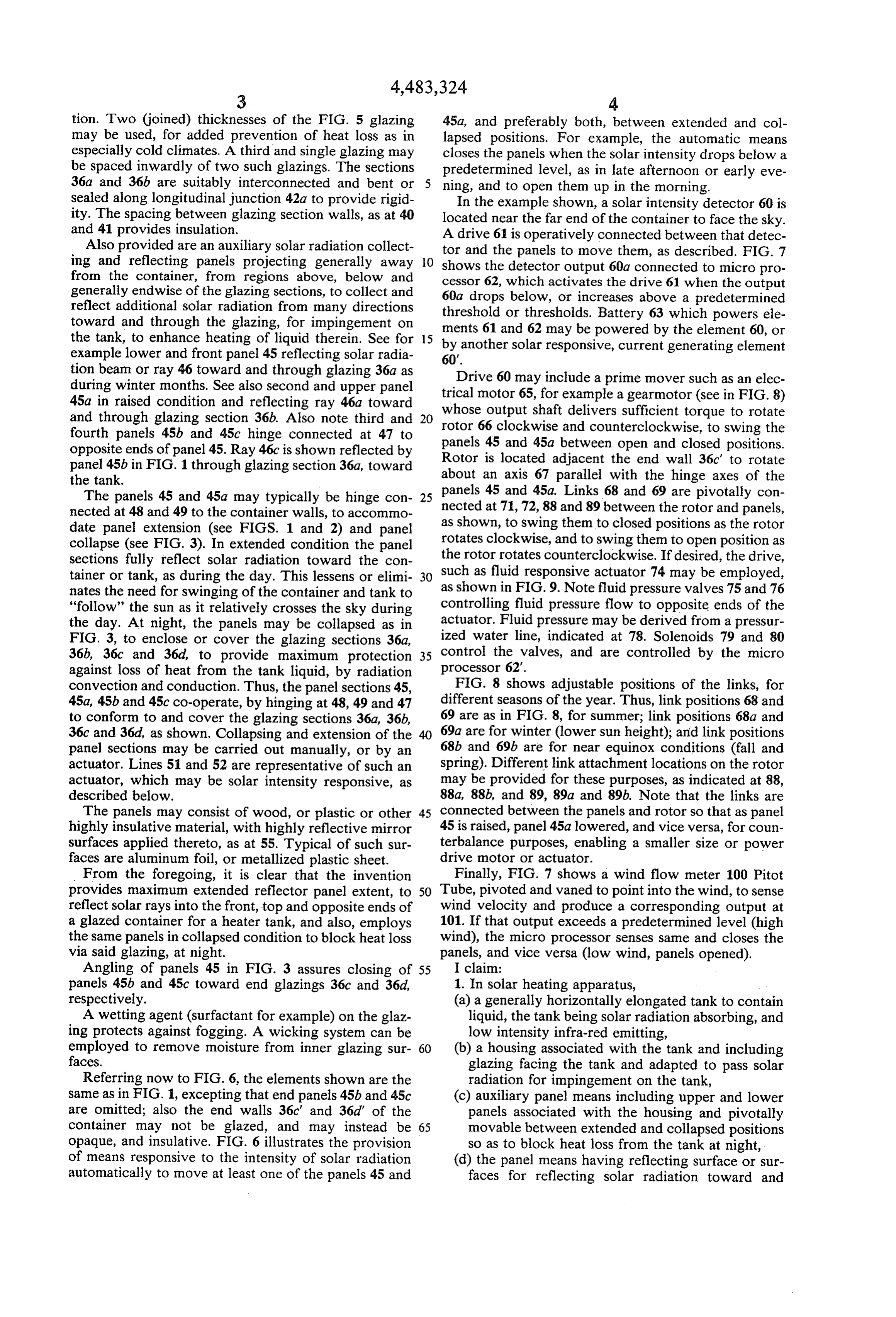
tion. Two (joined) thicknesses of the FIG. 5 glazing 45a, and preferably both, between extended and col may be used, for added prevention of heat loss as in lapsed positions. For example, the automatic means especially cold climates. A third and single glazing may closes the panels when the solar intensity drops below a be spaced inwardly of two such glazings. The sections predetermined level, as in late afternoon or early eve 36a and 36b are suitably interconnected and bent or 5 ning, and to open them up in the morning. sealed along longitudinal junction 42a to provide rigid In the example shown, a solar intensity detector 60 is ity. The spacing between glazing section walls, as at 40 located near the far end of the container to face the sky. and 41 provides insulation.
Also provided are an auxiliary solar radiation collect A drive 61 is operatively connected between that detec tor and the panels to move them, as described. FIG. 7 ing and reflecting panels projecting generally away 10 shows the detector output 60a connected to micro pro from the container, from regions above, below and cessor 62, which activates the drive 61 when the output generally endwise of the glazing sections, to collect and 60a drops below, or increases above a predetermined reflect additional solar radiation from many directions threshold or thresholds. Battery 63 which powers ele toward and through the glazing, for impingement on ments 61 and 62 may be powered by the element 60, or the tank, to enhance heating of liquid therein. See for 15 by another solar responsive, current generating element example lower and front panel 45 reflecting solar radia 60'.
tion beam or ray 46 toward and through glazing 36a as Drive 60 may include a prime mover such as an elec during winter months. See also second and upper panel trical 45a in raised condition and reflecting ray 46a toward whosemotor 65, for example a gearmotor (see in FIG. 8) and through glazing section 36b. Also note third and 20 rotor 66output shaft delivers sufficient torque to rotate clockwise and counterclockwise, to swing the fourth panels 45b and 45c hinge connected at 47 to opposite ends of panel 45. Ray 46c is shown reflected by panels 45 and 45a between open and closed positions. Rotor is located adjacent the end wall 36c to rotate panel 45b in FIG. 1 through glazing section 36a, toward about an axis 67 parallel with the hinge axes of the the tank.
The panels 45 and 45a may typically be hinge con- 25 panels 45 and 45a. Links 68 and 69 are pivotally con nected at 48 and 49 to the container walls, to accommo nected at 71,72, 88 and 89 between the rotor and panels, date panel extension (see FIGS. 1 and 2) and panel as shown, to swing them to closed positions as the rotor collapse (see FIG. 3). In extended condition the panel rotates clockwise, and to swing them to open position as sections fully reflect solar radiation toward the con the rotor rotates counterclockwise. If desired, the drive, tainer or tank, as during the day. This lessens or elimi- 30 such as fluid responsive actuator 74 may be employed, nates the need for swinging of the container and tank to as shown in FIG. 9. Note fluid pressure valves 75 and 76 "follow' the sun as it relatively crosses the sky during controlling fluid pressure flow to opposite ends of the the day. At night, the panels may be collapsed as in actuator. Fluid pressure may be derived from a pressur FIG. 3, to enclose or cover the glazing sections 36a, ized water line, indicated at 78. Solenoids 79 and 80 36b, 36c and 36d, to provide maximum protection 35 processorcontrol the valves, and are controlled by the micro against loss of heat from the tank liquid, by radiation 62.
convection and conduction. Thus, the panel sections 45, FIG. 8 shows adjustable positions of the links, for 45a, 45b and 45c co-operate, by hinging at 48, 49 and 47 different seasons of the year. Thus, link positions 68 and to conform to and cover the glazing sections 36a, 36b, 69 are as in FIG. 8, for summer; link positions 68a and 36c and 36d, as shown. Collapsing and extension of the 40 69a are for winter (lower sun height); and link positions panel sections may be carried out manually, or by an 68b and 69b are for near equinox conditions (fall and actuator. Lines 51 and 52 are representative of such an spring). Different link attachment locations on the rotor actuator, which may be solar intensity responsive, as may be provided for these purposes, as indicated at 88, described below. 88a, 88b, and 89, 89a and 89b. Note that the links are The panels may consist of wood, or plastic or other 45 connected between the panels and rotor so that as panel highly insulative material, with highly reflective mirror 45 is raised, panel 45a lowered, and vice versa, for coun surfaces applied thereto, as at 55. Typical of such sur terbalance purposes, enabling a smaller size or power faces are aluminum foil, or metallized plastic sheet. drive motor or actuator.
From the foregoing, it is clear that the invention Finally, FIG. 7 shows a wind flow meter 100 Pitot provides maximum extended reflector panel extent, to 50 Tube, pivoted and vaned to point into the wind, to sense reflect solar rays into the front, top and opposite ends of wind velocity and produce a corresponding output at a glazed container for a heater tank, and also, employs 101. If that output exceeds a predetermined level (high the same panels in collapsed condition to block heat loss wind), the micro processor senses same and closes the via said glazing, at night. panels, and vice versa (low wind, panels opened). Angling of panels 45 in FIG. 3 assures closing of 55 I claim:
panels 45b and 45c toward end glazings 36c and 36d, 1. In solar heating apparatus, respectively. (a) a generally horizontally elongated tank to contain A wetting agent (surfactant for example) on the glaz liquid, the tank being solar radiation absorbing, and ing protects against fogging. A wicking system can be low intensity infra-red emitting, employed to remove moisture from inner glazing sur- 60 (b) a housing associated with the tank and including faces. glazing facing the tank and adapted to pass solar Referring now to FIG. 6, the elements shown are the radiation for impingement on the tank, same as in FIG. 1, excepting that end panels 45b and 45c (c) auxiliary panel means including upper and lower are omitted; also the end walls 36c' and 36d' of the panels associated with the housing and pivotally container may not be glazed, and may instead be 65 movable between extended and collapsed positions opaque, and insulative. FIG. 6 illustrates the provision so as to block heat loss from the tank at night, of means responsive to the intensity of solar radiation (d) the panel means having reflecting surface or sur automatically to move at least one of the panels 45 and faces for reflecting solar radiation toward and
Page 6
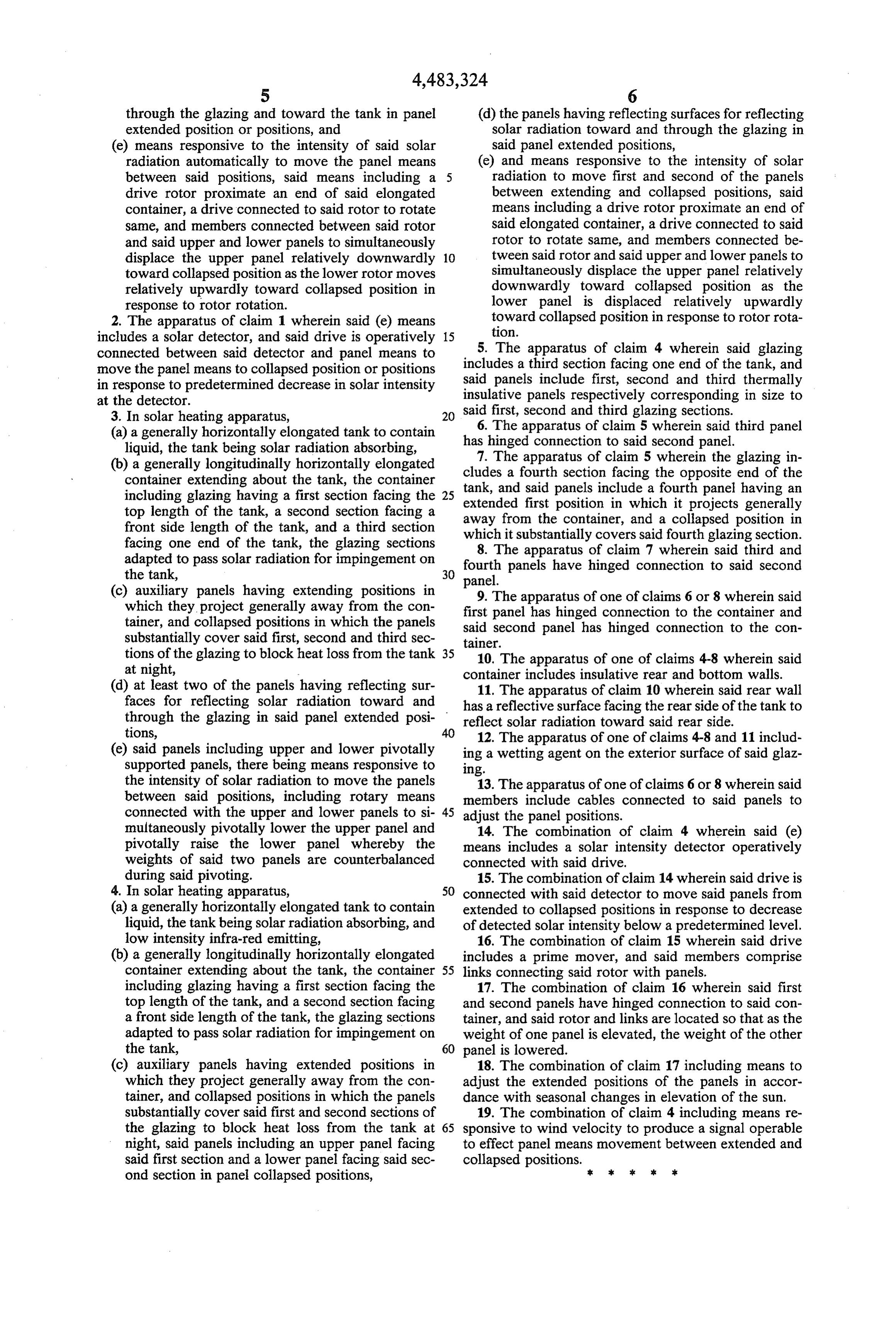
through the glazing and toward the tank in panel (d) the panels having reflecting surfaces for reflecting extended position or positions, and solar radiation toward and through the glazing in (e) means responsive to the intensity of said solar said panel extended positions, radiation automatically to move the panel means (e) and means responsive to the intensity of solar between said positions, said means including a 5 radiation to move first and second of the panels drive rotor proximate an end of said elongated between extending and collapsed positions, said container, a drive connected to said rotor to rotate means including a drive rotor proximate an end of same, and members connected between said rotor said elongated container, a drive connected to said and said upper and lower panels to simultaneously rotor to rotate same, and members connected be displace the upper panel relatively downwardly 10 tween said rotor and said upper and lower panels to toward collapsed position as the lower rotor moves simultaneously displace the upper panel relatively relatively upwardly toward collapsed position in downwardly toward collapsed position as the response to rotor rotation. lower panel is displaced relatively upwardly 2. The apparatus of claim 1 wherein said (e) means toward collapsed position in response to rotor rota includes a solar detector, and said drive is operatively 15 tion.
connected between said detector and panel means to 5. The apparatus of claim 4 wherein said glazing move the panel means to collapsed position or positions includes a third section facing one end of the tank, and said panels include first, second and third thermally in response to predetermined decrease in solar intensity insulative at the detector. panels respectively corresponding in size to 3. In solar heating apparatus, 20 said first, second and third glazing sections. (a) a generally horizontally elongated tank to contain 6. The apparatus of claim 5 wherein said third panel liquid, the tank being solar radiation absorbing, has hinged connection to said second panel. (b) a generally longitudinally horizontally elongated cludes7. The apparatus of claim 5 wherein the glazing in container extending about the tank, the container a fourth section facing the opposite end of the including glazing having a first section facing the 25 tank, and said panels include a fourth panel having an extended first position in which it projects generally top length of the tank, a second section facing a away from the container, and a collapsed position in front side length of the tank, and a third section facing one end of the tank, the glazing sections which 8.
it substantially covers said fourth glazing section.
The apparatus of claim 7 wherein said third and adapted to pass solar radiation for impingement on fourth panels have hinged connection to said second the tank, panel.
(c) auxiliary panels having extending positions in 9. The apparatus of one of claims 6 or 8 wherein said which they project generally away from the con first tainer, and collapsed positions in which the panels said panel second has hinged connection to the container and panel has hinged connection to the con substantially cover said first, second and third sec tainer.
tions of the glazing to block heat loss from the tank 35 10. The apparatus of one of claims 4-8 wherein said at night, container includes insulative rear and bottom walls. (d) at least two of the panels having reflecting sur 11. The apparatus of claim 10 wherein said rear wall faces for reflecting solar radiation toward and has a reflective surface facing the rear side of the tank to through the glazing in said panel extended posi reflect solar radiation toward said rear side.
(e) said panels including upper and lower pivotally ing12.a wettingThe apparatus of one of claims 4-8 and 11 includ agent on the exterior surface of said glaz supported panels, there being means responsive to ing.
the intensity of solar radiation to move the panels 13. The apparatus of one of claims 6 or 8 wherein said between said positions, including rotary means members include cables connected to said panels to connected with the upper and lower panels to si 45 adjust the panel positions.
multaneously pivotally lower the upper panel and 14. The combination of claim 4 wherein said (e) pivotally raise the lower panel whereby the means includes a solar intensity detector operatively weights of said two panels are counterbalanced connected with said drive.
during said pivoting. 15. The combination of claim 14 wherein said drive is 4. In solar heating apparatus, 50 connected with said detector to move said panels from (a) a generally horizontally elongated tank to contain extended to collapsed positions in response to decrease liquid, the tank being solar radiation absorbing, and of detected solar intensity below a predetermined level. low intensity infra-red emitting, 16. The combination of claim 15 wherein said drive (b) a generally longitudinally horizontally elongated includes a prime mover, and said members comprise container extending about the tank, the container 55 links connecting said rotor with panels. including glazing having a first section facing the 17. The combination of claim 16 wherein said first top length of the tank, and a second section facing and second panels have hinged connection to said con a front side length of the tank, the glazing sections tainer, and said rotor and links are located so that as the adapted to pass solar radiation for impingement on weight of one panel is elevated, the weight of the other the tank, 60 panel is lowered.
(c) auxiliary panels having extended positions in 18. The combination of claim 17 including means to which they project generally away from the con adjust the extended positions of the panels in accor tainer, and collapsed positions in which the panels dance with seasonal changes in elevation of the sun. substantially cover said first and second sections of 19. The combination of claim 4 including means re the glazing to block heat loss from the tank at 65 sponsive to wind velocity to produce a signal operable night, said panels including an upper panel facing to effect panel means movement between extended and said first section and a lower panel facing said sec collapsed positions. x ond section in panel collapsed positions, 2:
Provenance
- Collection
- Cited prior art
- Original PDF
- patentimages.storage.googleapis.com →
- Filed
- 1983-05-16
- Pages
- 6
- Method
- pdftotext (the PDF's own text layer) + pdftoppm 300dpi page scans
- Source
- Google Patents bibliographic record
- Granted
- 1984-11-20
- Inventors
- Pierra H. Fromm
- Transcribed from
- patentimages.storage.googleapis.com →