patent · US4590993
Heat transfer device for the transport of large conduction flux without net mass transfer
27 May 1986
Page 1 — bibliographic record
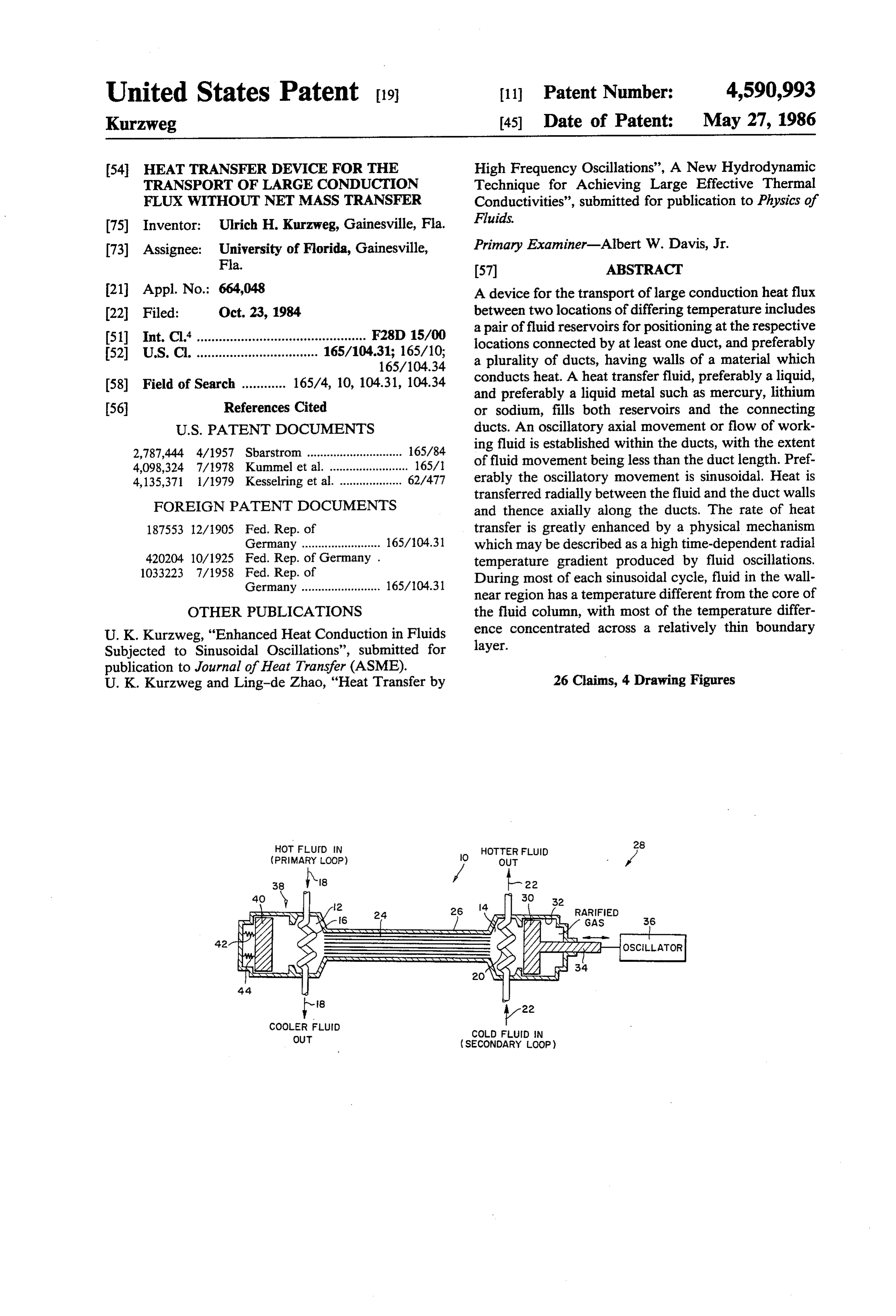
United States Patent (19) 11 Patent Number: 4,590,993 Kurzweg 45) Date of Patent: May 27, 1986 54 HEAT TRANSFER DEVICE FOR THE High Frequency Oscillations', A New Hydrodynamic TRANSPORT OF LARGE CONDUCTION Technique for Achieving Large Effective Thermal FLUX WITHOUT NET MASS TRANSFER Conductivities', submitted for publication to Physics of Inventor: Ulrich H. Kurzweg, Gainesville, Fla. Fluids.
(73) Assignee: University of Florida, Gainesville, Primary Examiner-Albert W. Davis, Jr. Fla. 57 ABSTRACT 21 Appl. No.: 664,048 A device for the transport of large conduction heat flux 22 Filed: Oct. 23, 1984 between two locations of differing temperature includes a pair of fluid reservoirs for positioning at the respective (51) Int. Cl'.............................................. F28D 15/00 locations connected by at least one duct, and preferably (52) U.S. C. ................................. 165/104.31; 165/10; a plurality of ducts, having walls of a material which
(58) Field of Search ............ 165/4, 10, 104.31, 104.34 conducts heat. A heat transfer fluid, preferably a liquid, and preferably a liquid metal such as mercury, lithium 56 References Cited or sodium, fills both reservoirs and the connecting
2,787,444 4/1957 Sbarstrom ............................. 165/84 ing fluid is established within the ducts, with the extent 4,098,324 7/1978 Kummel et al. ........ ... 165/1 of fluid movement being less than the duct length. Pref 4,135,371 1/1979 Kesselring et al. ................... 62/477 erably the oscillatory movement is sinusoidal. Heat is transferred radially between the fluid and the duct walls
FOREIGN PATENT DOCUMENTS and thence axially along the ducts. The rate of heat 187553 12/1905 Fed. Rep. of transfer is greatly enhanced by a physical mechanism Germany ........................ 165/104.31 which may be described as a high time-dependent radial 420204 10/1925 Fed. Rep. of Germany . temperature gradient produced by fluid oscillations. 1033223 7/1958 Fed. Rep. of During most of each sinusoidal cycle, fluid in the wall
near region has a temperature different from the core of
OTHER PUBLICATIONS the fluid column, with most of the temperature differ U. K. Kurzweg, "Enhanced Heat Conduction in Fluids ence concentrated across a relatively thin boundary Subjected to Sinusoidal Oscillations”, submitted for layer.
publication to Journal of Heat Transfer (ASME).
U. K. Kurzweg and Ling-de Zhao, "Heat Transfer by 26 Claims, 4 Drawing Figures
(PRIMARY LOOP)
OUT
(SECONDARY LOOP)
Page 2
Drawing sheet — no readable text.
Page 3
Drawing sheet — no readable text.
Page 4
Drawing sheet — no readable text.
Page 5
Drawing sheet — no readable text.
Page 6
needed for liquid vaporization and the temperature
HEAT TRANSFER DEVICE FOR THE needed for condensation.
TRANSPORT OF LARGE CONDUCTION FLUX Briefly, a heat transfer device in accordance with the WITHOUT NET MASSTRANSFER invention includes a pair of fluid reservoirs adapted for positioning at respective locations of differing tempera
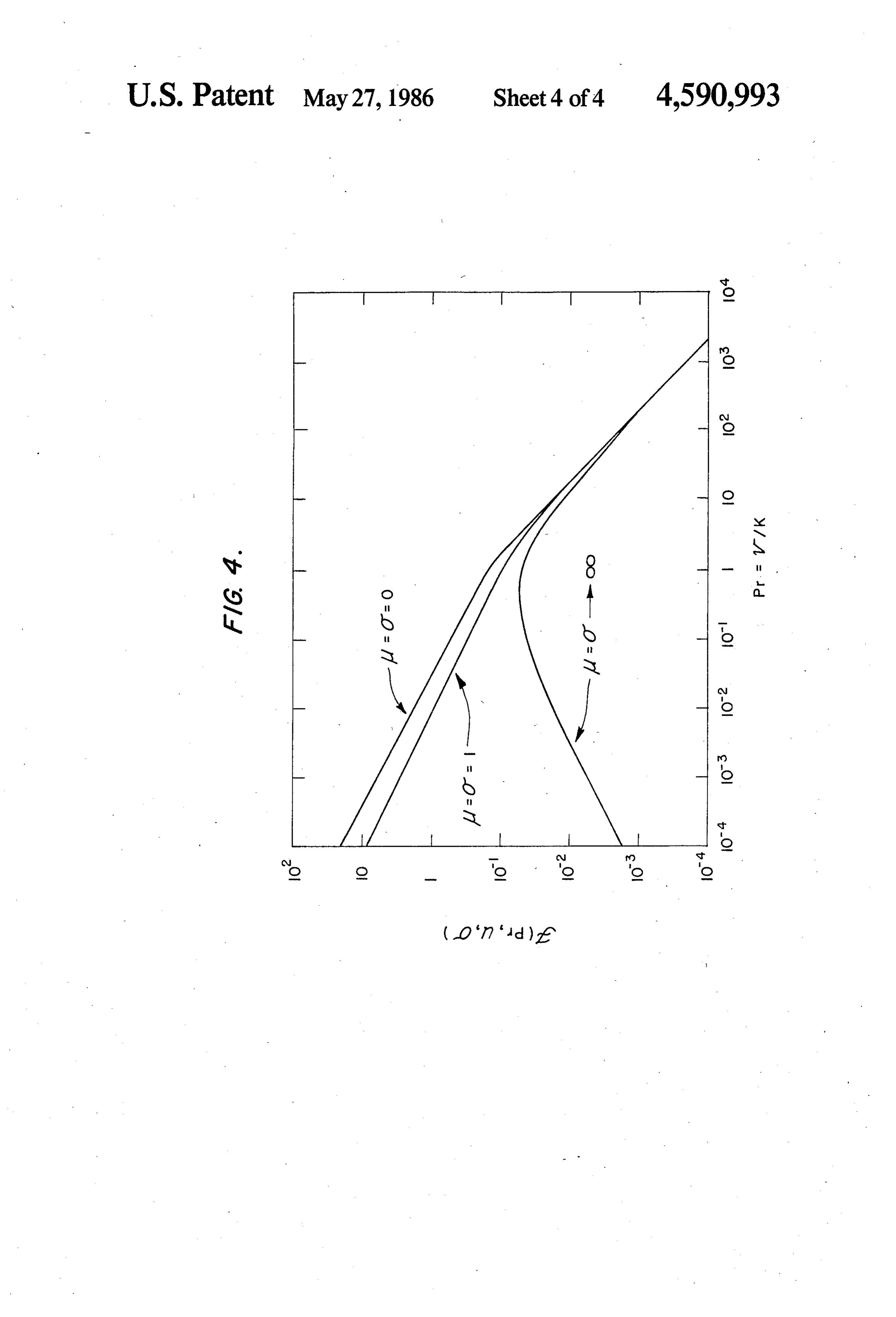
BACKGROUND OF THE INVENTION tures between which it is desired to transfer heat. At The present invention relates to a device for very ducts least one duct having walls of a material which con large conduction heat transfers without a concomitant bodiments, heat connects the fluid reservoirs. In typical em mass transfer. The present invention can be employed in 10 ing the fluidthere are a plurality of such ducts connect any situation where a heat pipe might otherwise be any one of a variety ofThe reservoirs. plurality of ducts can have particular configurations. One employed, but the present invention is superior to a heat configuration example is a bundle of metallic tubes pipe in several respects. The invention has particular supported within an overall outer tube, preferably ther utility in the rapid removal of heat from fluids which mally insulated. In this particular configuration, ducts are radioactive (such as in nuclear reactors), as well as 15 are defined in two general regions: within the tubes, as from fluids having undesirable chemical properties and well as in the approximately triangular interstitial which must remain isolated from the environment. spaces defined between the outer walls of adjacent Although the present invention is quite distinct from tubes. As another configuration example, a six-sided a heat pipe, heat pipes nevertheless provide a conve elongated honeycomb structure or similar three- or nient reference point for purposes of comparison. As is 20 well known, in principle a heat pipe is an elongated four-sided structure may be provided. A quantity of heat transfer fluid, preferably liquid, cylinder containing a working fluid which changes fills the ducts and reservoirs. Preferably there are no between the liquid and the gas phases during operation. void spaces within the system and thus the reservoirs The heat pipe absorbs heat at one end by vaporization are completely filled. For maximum heat transfer, a of working fluid, and releases heat at the other end by 25 liquid metal is employed as the heat transfer fluid, such condensation of the resultant vapor. The liquid conden as mercury, liquid lithium or liquid sodium. sate returns to the heat absorbing end by capillarity Greatly enhanced heat transfer between the two fluid through a capillary structure, for example covering the reservoirs is effected by providing a means for establish internal face of the cylinder. The process proceeds ing an oscillatory axial movement or flow of working continuously, and the resultant heat transfer of a heat 30 fluid within the ducts, with the extent of fluid move pipe may be 10,000 times or more higher than the con ment being less than the duct length. Preferably the ductive heat transfer of a solid copper or silver rod. oscillatory movement is sinusoidal. While heat pipes have found wide application, they In the disclosed embodiments, the oscillatory axial nevertheless have two disadvantages in particular movement is established by an oscillatory displacement which are overcome by the present invention. One 35 device acting on fluid within one of the reservoirs. Two disadvantage of heat pipes is that the working fluid examples of suitable oscillatory displacement devices within the heat pipe continuously recirculates during are a piston acting within a suitable cylinder either operation from one end to the other. Thus there is mass comprising a part of the one reservoir or connected transfer from one end to the other. This is particularly directed to the one reservoir, and a flexible diaphragm disadvantageous in the case of heat removal from radio 40 comprising a wall of the one reservoir and acted on by active fluids because radioactivity is in effect carried an external shaking device. Whatever the specific form, from one end of the heat pipe to the other as the entire the oscillatory displacement device functions to alter volume of working fluid becomes radioactive. A second nately displace fluid within the one reservoir such that disadvantage of heat pipes is that a given heat pipe, working fluid is caused to move axially in one direction depending upon the particular working fluid selected 45 through the ducts, and then to in effect draw heat trans and the internal pressure, can function only over a par fer fluid back into the one reservoir such that heat trans ticular range of temperatures. Specifically, the tempera fer fluid moves in the opposite direction within the ture at the heat-absorbing (relatively hotter) end of the ducts. Thus, within the ducts, fluid oscillates in alter heat pipe must be at least high enough for vaporization nate axial directions at a predetermined frequency and of liquid phase working fluid, and the temperature at 50 with a predetermined tidal displacement or amplitude. the heat-releasing (relatively colder) end of the pipe As noted above, the extent of fluid movement within must be at least low enough for condensation of gas the tubes is less than the length of the tubes such that phase working fluid. there is no net transfer of heat exchange fluid from one In addition to avoiding these two disadvantages, the of the reservoirs to the other. While some migration present invention provides much higher heat transport 55 may occur slowly by diffusion, such mass transfer by rates. Embodiments of the present invention can pro diffusion is not great, particularly where the heat trans vide heat transport rates several orders of magnitude fer fluid is a liquid metal such as mercury, or even liquid greater than that of existing heat pipes. lithium or liquid sodium at higher temperatures. In any
SUMMARY OF THE INVENTION
event, the operation of the invention requires only an oscillatory movement, and thus operation of the inven
Accordingly, it is an object of the invention to pro tion requires no net mass transfer whatsoever. vide structures for the transport of large conduction Since the preferred liquid heat transfer fluid is sub heat flux. stantially incompressible, a displacement accommodat It is another object of the invention to provide such ing device is provided at the other one of the reservoirs devices which operate without net mass transfer. 65 acted on by fluid therewithin. A suitable displacement It is another object of the invention to provide such accommodating device can comprise a similar, al devices which avoid the working temperature limita though passive piston, preferably with resilient biasing tions of heat pipes which follow from the temperature elements such that energy is returned to the driving
Page 7
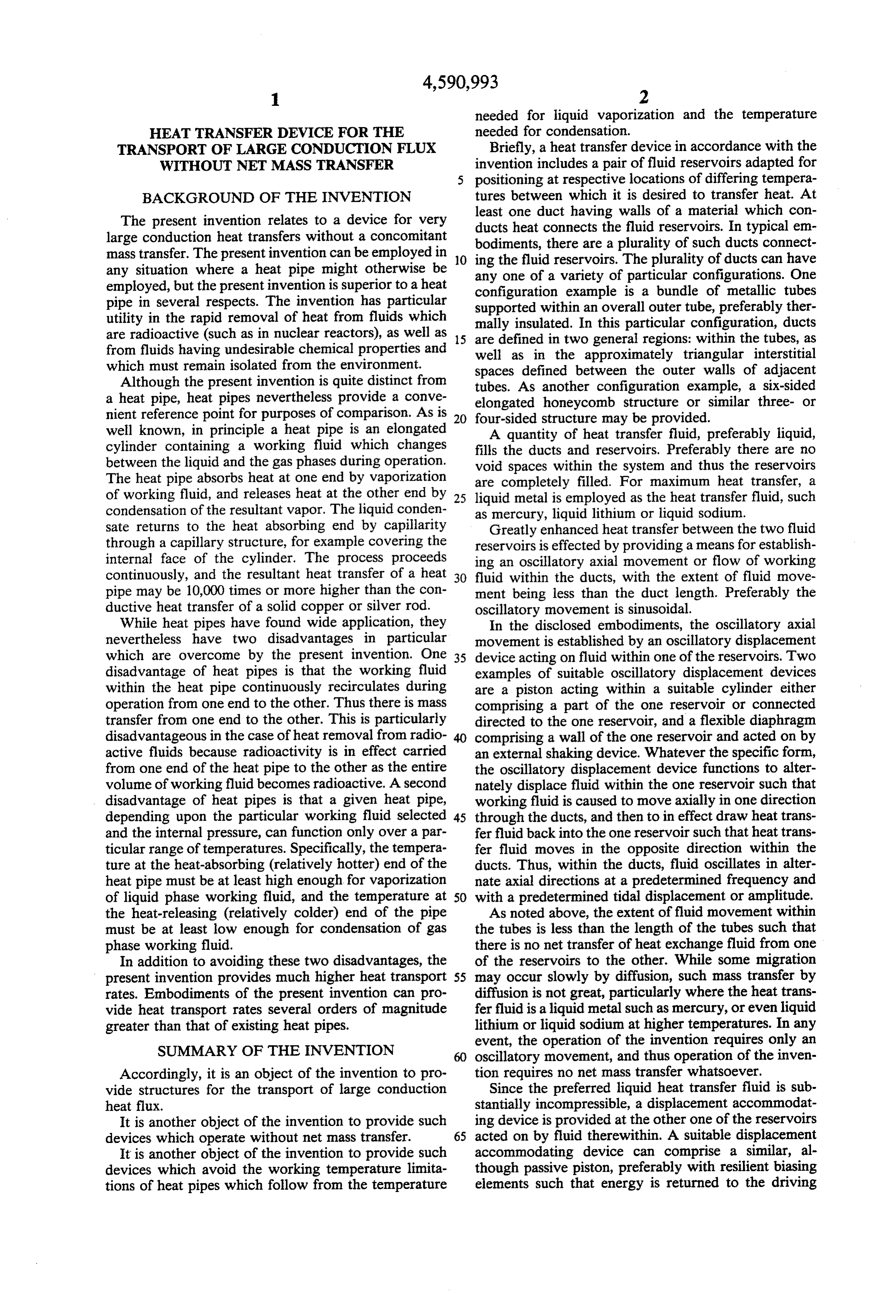
piston on the return stroke of the driving piston. As this general relationship to the structures of the inven another example, the displacement accommodating tion, the thermal conductivity is that of the tube walls device can comprise a simple diaphragm or membrane and the heat transfer fluid. Thus, the thermal conductiv comprising one of the walls of the other reservoir, pref ity factor is subject to predictable contraints. As men erably backed by a gas-filled sealed chamber. tioned above, to maximize heat transfer, liquid metals With this arrangement, large quantities of heat are are preferred as the heat transfer fluid. The area over transported axially along the ducts, provided the fluid is which heat transfer takes place in this relationship is the osciliated at sufficiently high frequency and with a suffi area within the ducts over which the duct walls and the ciently large tidal displacement. As is described next heat transfer fluid interface. The area factor is also sub below, the heat transfer mechanism is a highly en 10 ject to predictable constraints.
hanced heat conduction process involving symmetrical The third factor, temperature gradient, is another oscillatory heat transfer between the heat transfer fluid matter, not subject to constraints which are obvious. and the walls of the ducts. The operation is explained More particularly, in accordance with one aspect of the below first in overview, and then with a more detailed invention, the temperature gradient factor is greatly explanation of the mechanism by which highly en 15 increased beyond that which might be expected due to hanced heat transfer occurs. Finally, a detailed mathe the formation of a boundary layer across which temper matical analysis is included as an Appendix at the end of ature differences are concentrated. this specification. As is known, wherever a viscous fluid flows past a For purposes of explanation, it will be assumed that boundary, the layers of the fluid nearest the boundary heat is being transferred from the relatively hotter res 20 are subjected to shearing forces, which cause the veloc ervoir which includes an oscillatory displacement de ity of these layers to be reduced. As the boundary is vice in the form of a piston, to the relatively colder approached, the velocity continuously decreases until, reservoir. An exemplary cycle begins with the piston immediately at the boundary, the fluid particles are at moving on its forward stroke to displace heat transfer rest relative to the body. This region of retarded veloc fluid from within the hotter reservoir such that fluid 25 ity is called the boundary layer, and a graph of the moves within the ducts in the direction from the hotter variation of velocity with distance from the wall or towards the relatively cooler reservoir. During the boundary describes a boundary layer profile. The pri forward stroke, hot regions of the fluid moving into mary effects of the viscosity of the fluid are concen contact with duct walls which are relatively cooler. trated in this boundary layer, whereas in the outer or Thus, the hot fluid regions transfer heat into the walls of 30 free-stream flow the viscous forces are negligible. Thus the duct, portions of which consequently increase in in a closed conduit or duct the free-stream flow occurs temperature. On the return stroke, heat transfer fluid is in a moving fluid column centered on the axis of the drawn in the opposite direction through the ducts. Dur duct. The boundary layer may be viewed as a sheath ing the return stroke, relatively cooler regions of heat around the moving column.
transfer fluid move into contact with the just-heated 35 It will accordingly be appreciated that, in the situa wall portions, and heat thus flows from these wall por tion of the present invention, such a boundary layer is tions to the fluid regions. created during each oscillatory movement of fluid This action continues in oscillatory manner and, once within the ducts. An important consequence follows operation gets underway, heat is effectively transferred from the existence of this boundary layer. in increments, the spacing between which is determined In particular, with a sufficiently thermally-conduc by the tidal displacement of heat exchange fluid within tive heat transfer fluid and with an appropriate duct the ducts. At particular instants during operation, there size, i.e. diameter, the temperature of the moving fluid exist localized alternating relatively hotter and rela column is constant, relatively speaking, from the center tively colder duct wall portions, and localized relatively of the column up to the bondary layer. During most of hotter and relatively colder fluid regions in motion 45 each cycle, the heat transfer fluid in the portion of the relative to the wall portions. boundary layer region immediately adjacent the duct These hot and cold fluid regions which are set up wall has a temperature different from that of the fluid effectively interface each other through portions of the column within the duct. It is thus within the boundary wall to and from which heat is transferred in a symmet layer that the temperature difference between the fluid rical manner and which thus briefly store heat. Signifi 50 column and the duct wall is concentrated. The thinner cantly these hot and cold regions of the fluid which are the boundary layer the greater will be the temperature set up effectively interface each other over a much gradient.
larger area than the duct cross-section. As a result, by selection of frequency and displace Since the extent of fluid movement, i.e. the tidal dis ment (which together determine a velocity profile) the placement, is less than the length of the ducts and since 55 temperature gradient is made extremely high, and the the movement is strictly oscillatory, there is no net mass radial heat transfer rate between the fluid and the walls transfer during operation. Moreover, during this overall of the duct is correspondingly very high. The physical cycle, heat enters the wall, but then is given up on the mechanism resulting in enhanced heat transfer may be next part of the cycle. Thus, by symmetry, there is described as a high time-dependent radial temperature essentially no net heat transfer through the walls. 60 gradient produced by fluid oscillations. During most of While the foregoing provides an overview, it does each sinusoidal cycle the fluid in the wall-near region not fully explain the high rate of heat transfer achiev has a temperature different from the core of the fluid able with the subject invention. Such an explanation column. As a result, large quantities of heat are trans will now be provided. ported radially and hence axially. In general, rate of heat transfer is proportional to the 65 While a detailed mathematical analysis will be found product of three factors: Thermal conductivity, the area in the Appendix at the end of this specification, in gen over which heat transfer occurs, and temperature gradi eral it can be stated that the effective thermal diffusivity ent (temperature difference per unit distance). Applying is proportional to the square of the fluid displacement,
Page 8
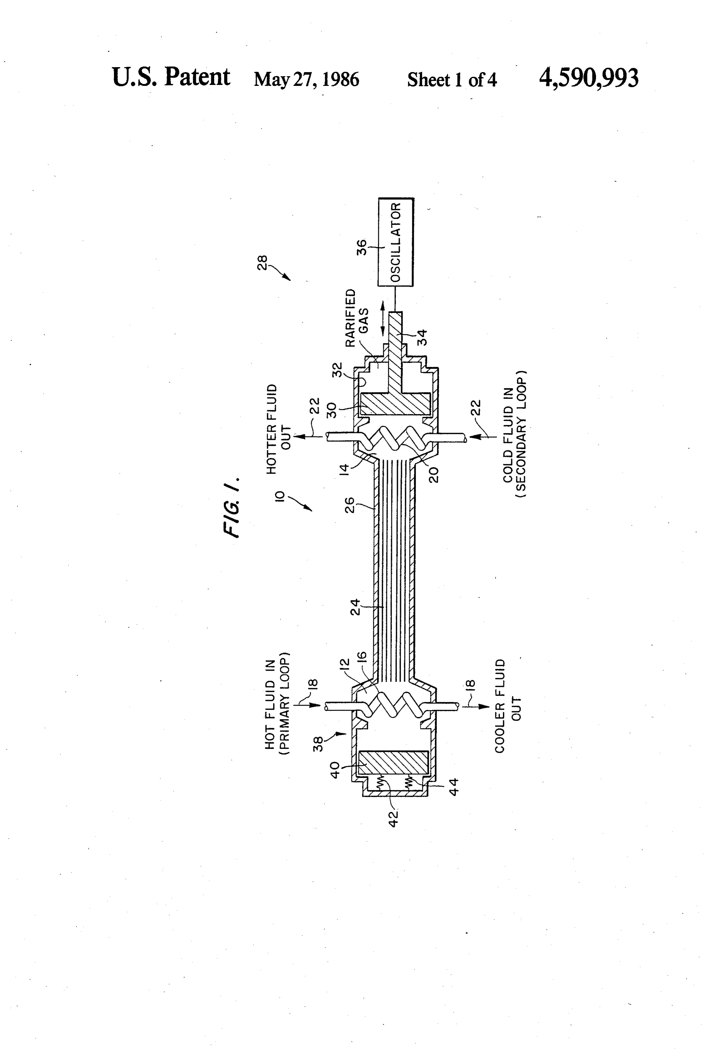
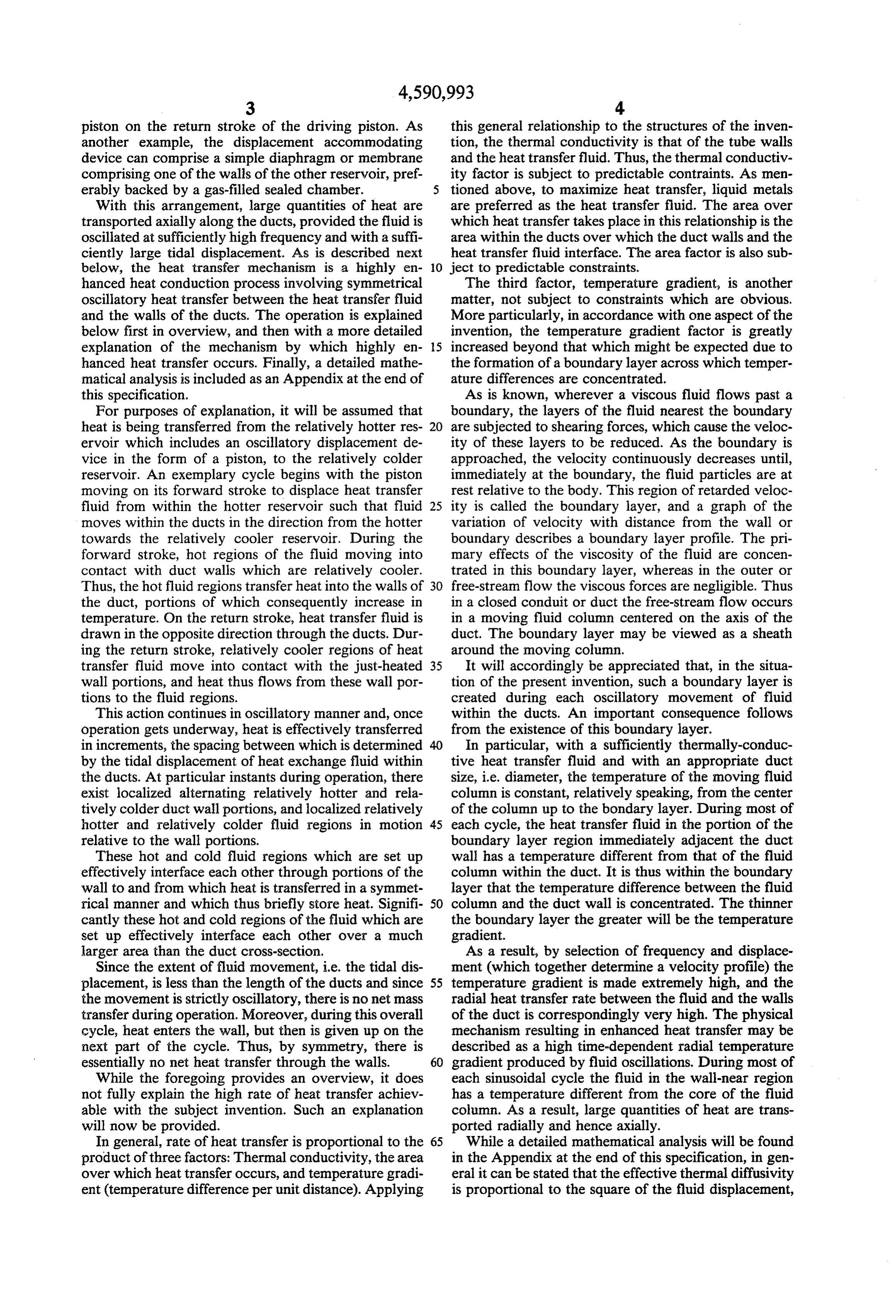
the square root of the frequency, and inversely to the The other fluid reservoir 14 is then the relatively size, e.g. diameter, of the ducts. Optimum heat transfer cooler reservoir. A corresponding heat exchanger 20 is occurs when the duct diameter is such that the time for located within the reservoir 14, and secondary loop thermal diffusion across the duct just equals one-half of 5 fluid represented by arrows 22 flows through the heat the oscillation period. By way of specific example, using exchanger 20 so as to extract heat from the system. liquid sodium as a heat transfer fluid at an oscillation The two reservoirs 12 and 14 are connected by at amplitude (tidal displacement) of 100 cm at a frequency least one, and preferably a plurality, of ducts 24 having of 30 Hz in metal tubes of 0.4 mm diameter each, an walls of a material which conducts heat. A quantity of axial heat flux of 1.3X 10¹⁰ watts/m2 can be achieved. heat transfer fluid fills the ducts 24 and at least portions, As another example, an experimental device was O but preferably the entireties of the reservoirs 12 and 14. constructed employing merely water as the heat trans Optimally, metal, such the heat transfer fluid comprises a liquid as mercury, lithium or sodium, and the fer fluid, and tubes (ducts) of glass. At an oscillation frequency of 8.0 Hz, with an axial fluid displacement, ducts 24 comprise a bundle of metal tubes, for example (i.e. amplitude) of 12.5 cm, the effective axial thermal 5 stainless steel, having a diameter in the order of 3 mm. conduction was measured to be 17,900 times that of the cal casingbundle
The tube
is confined within an overall cylindri having a thermally-insulating wall.
value predicted in the absence of oscillations. In other Acting on fluid between one of the reservoirs 12 and words, the water showed an effective thermal conduc 14, in this example within the reservoir 14, is an oscilla tivity about 25 times better than an equivalent copper tory rod of equal cross section. A more detailed description 20 ple, the oscillatory displacement adevice displacement device 28. As representative exam 28 comprises a of this experiment will also be found in the Appendix. driving piston 30 reciprocating within a cylindrical In any given case, there is an optimum size, i.e. diame 32 in direct communication with the reservoir 14bore and ter, of the ducts. (While the ducts are not necessarily driven via a shaft 34 by an external mechanical oscilla circular in cross section, for purposes of analysis, it is tor 36. Typically, the driving piston 30 oscillates sinu simpler to consider them as so.) If the duct diameter is 25 soidally, but any suitable oscillation waveform may be too small, then the boundary layer and the duct diame employed.
ter become equal. When this occurs, there is no concen Since the liquid heat transfer fluid is substantially tration of temperature difference to produce a large incompressible, in order to keep the system entirely temperature gradient, and thus the enhanced conduc filled with fluid at all times with no voids, a displace tion effect is lost. If the duct diameter is too large, then 30 ment accommodating device, generally designated 38, the heat transfer becomes less effective from the center is connected to the fluid reservoir 12. In the example of the moving fluid column to the boundary layer. With shown, the displacement accommodating device com metal fluids, due to their relatively good thermal con prises what may be viewed as a passive piston 40 resil ductivities, diameters of 3.0 mm can be used, with fre iently supported by springs 42 and backed by a sealed quencies within the approximate range of 2.0 to 50,0Hz. 35 chamber 44 of compressed gas. With this arrangement, BRIEF DESCRIPTION OF THE DRAWINGS as the piston 30 oscillates, it will be appreciated that heat transfer fluid moves alternately axially in opposite
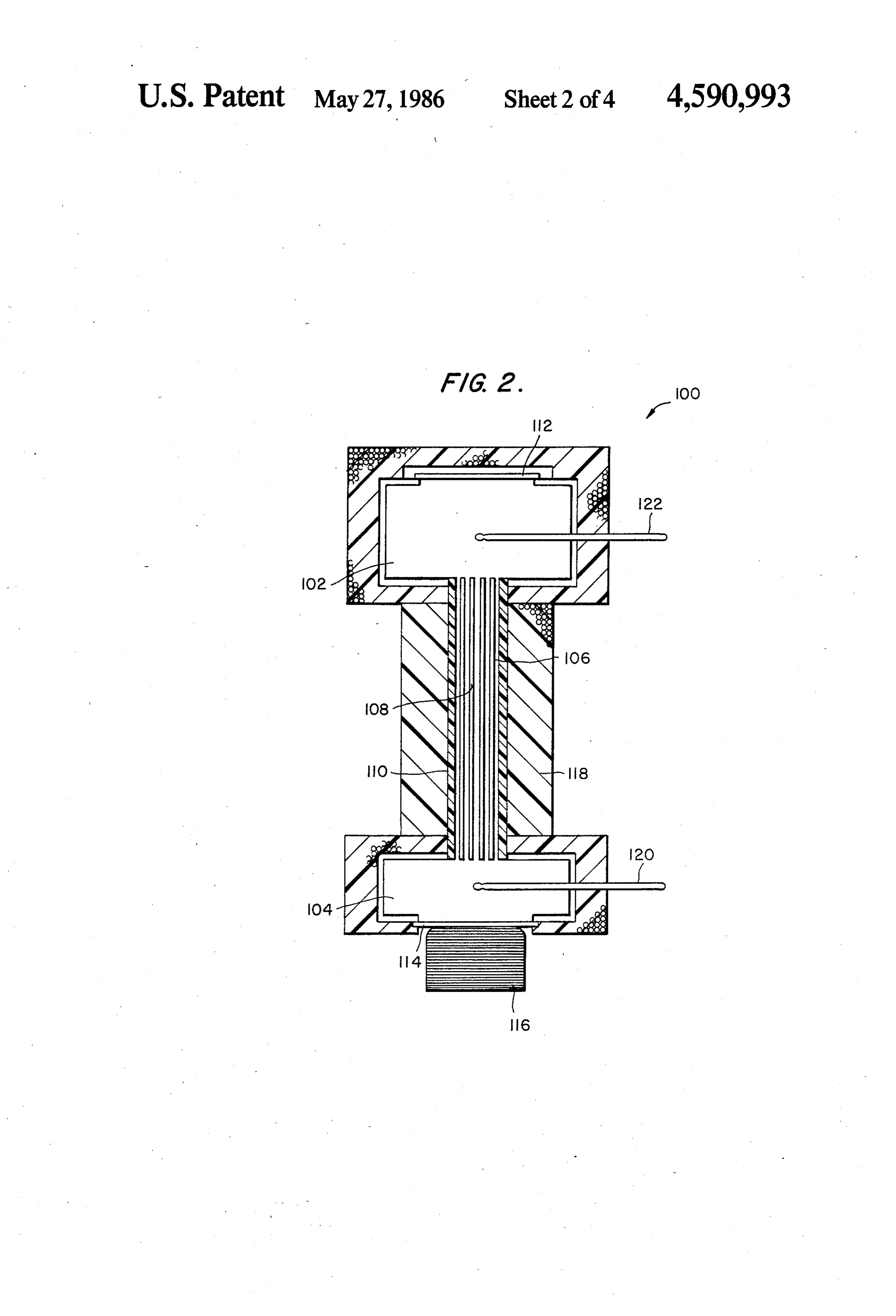
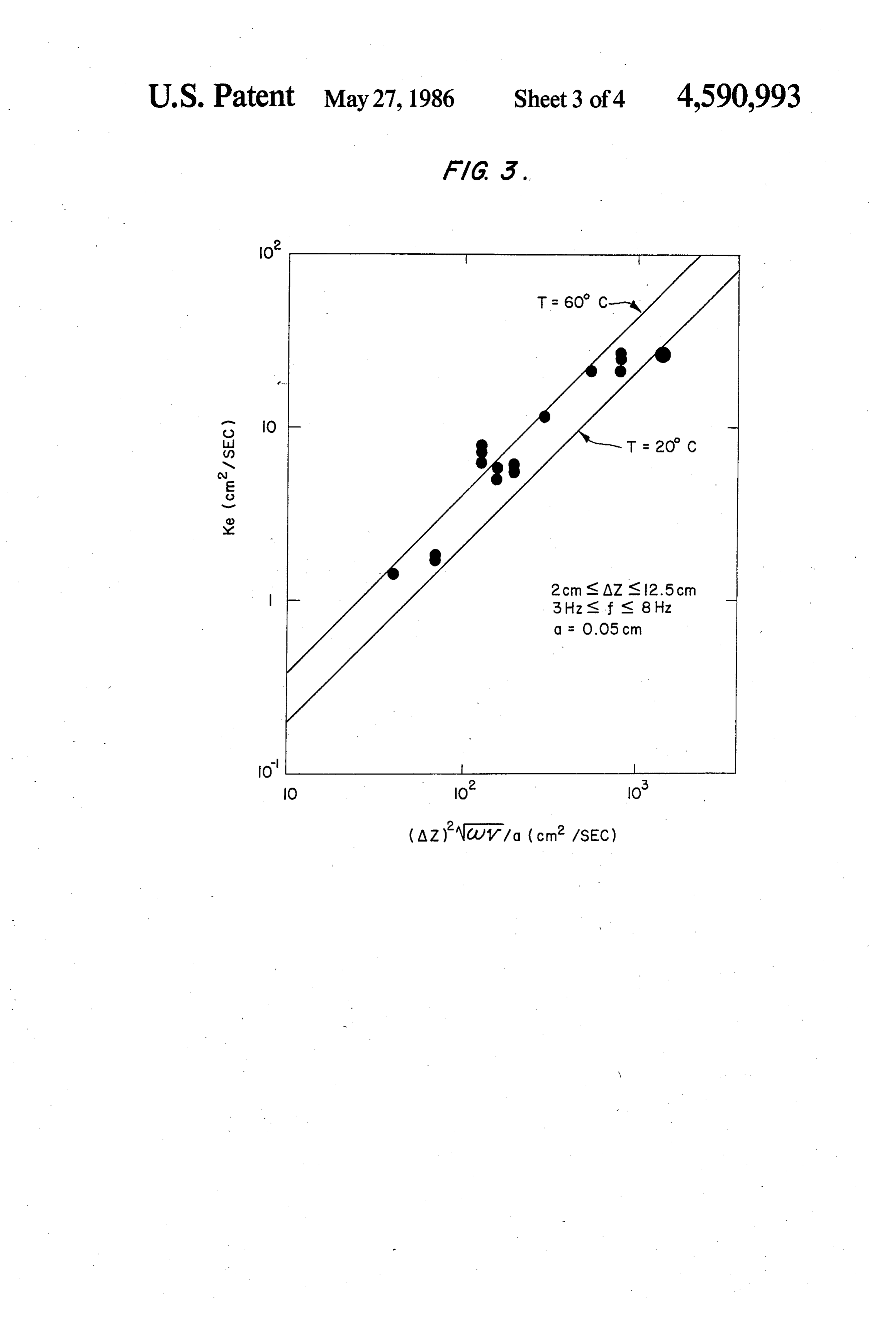
While the novel features of the invention are set forth directions within the ducts 24. It will be appreciated with particularity in the appended claims, the invention, that, by this arrangement, the passive piston 40, due to both as to organization and content, will be better un 40 its resilient support, returns energy to the driving piston derstood and appreciated, along with other objects and 30. As noted above, the oscillation amplitude is selected features thereof, from the following detailed descrip such that the extent of fluid movement within the ducts tion, taken in conjunction with the drawings in which: 24 is less than the length of the ducts. FIG. 1 is a cross-sectional view of one form of heat In operation, as will be understood in light of the transfer device in accordance with the invention; 45 foregoing "Summary of the Invention', when the fluid FIG. 2 is a similar cross-sectional view of an experi within the ducts 24 is set into oscillatory axial move mental device; ment, a time-dependent boundary layer is formed along FIG. 3 is a plot of experimentally-observed thermal the metal duct walls, and a large radial temperature diffusivity as a function of tidal displacement and oscil gradient is established across this boundary layer. Hot lation frequency at the highest and lowest temperatures 50 and cold portions of the working fluid thus interface encountered during the experiments; and each other over a much larger area than the duct cross FIG. 4 is a plot depicting the effects of Prandtl num section, leading to a very large increase in radial and ber, wall conductivity, and fluid conductivity. subsequent axial heat transport. DESCRIPTION OF PREFERRED It is believed that the principles, operation, and exem 55 plary embodiments of the invention will all be under
EMBODIMENTS stood from the foregoing. Presented next in Appendix Referring first to FIG. 1, a heat transfer device 10 in form are experimental results and a more rigorous math accordance with the invention includes a pair of fluid ematical analysis of enhanced conduction heat transfer reservoirs 12 and 14 adapted for positioning at respec via sinusoidal oscillatory flow through circular tubes tive locations of differing temperature between which it 60 connecting two fluid reservoirs maintained at different is desired to transfer heat. By way of example, the reser temperatures. This Appendix is based on two papers voir 12 is a relatively hotter reservoir and is positioned published subsequently to the filing date hereof; U. H. so as to remove heat from radioactive material (not Kurzweg, “Enhanced Heat Conduction in Fluids Sub shown). An exemplary heat exchanger 16 is provided jected to Sinusoidal Oscillations', Journal of Heat within the reservoir 12, and radioactive primary loop 65 Transfer (ASME), Vol. 107, pages 459-462, May 1985; fluid, represented by arrows 18, passes through the heat and U. H. Kurzweg and Ling-de Zhao, "Heat Transfer exchanger 16 and is cooled as heat is transferred to fluid by High Frequency Oscillations; A new Hydrodynamic within the reservoir 12. Technique for Achieving Large Effective Thermal
Page 9
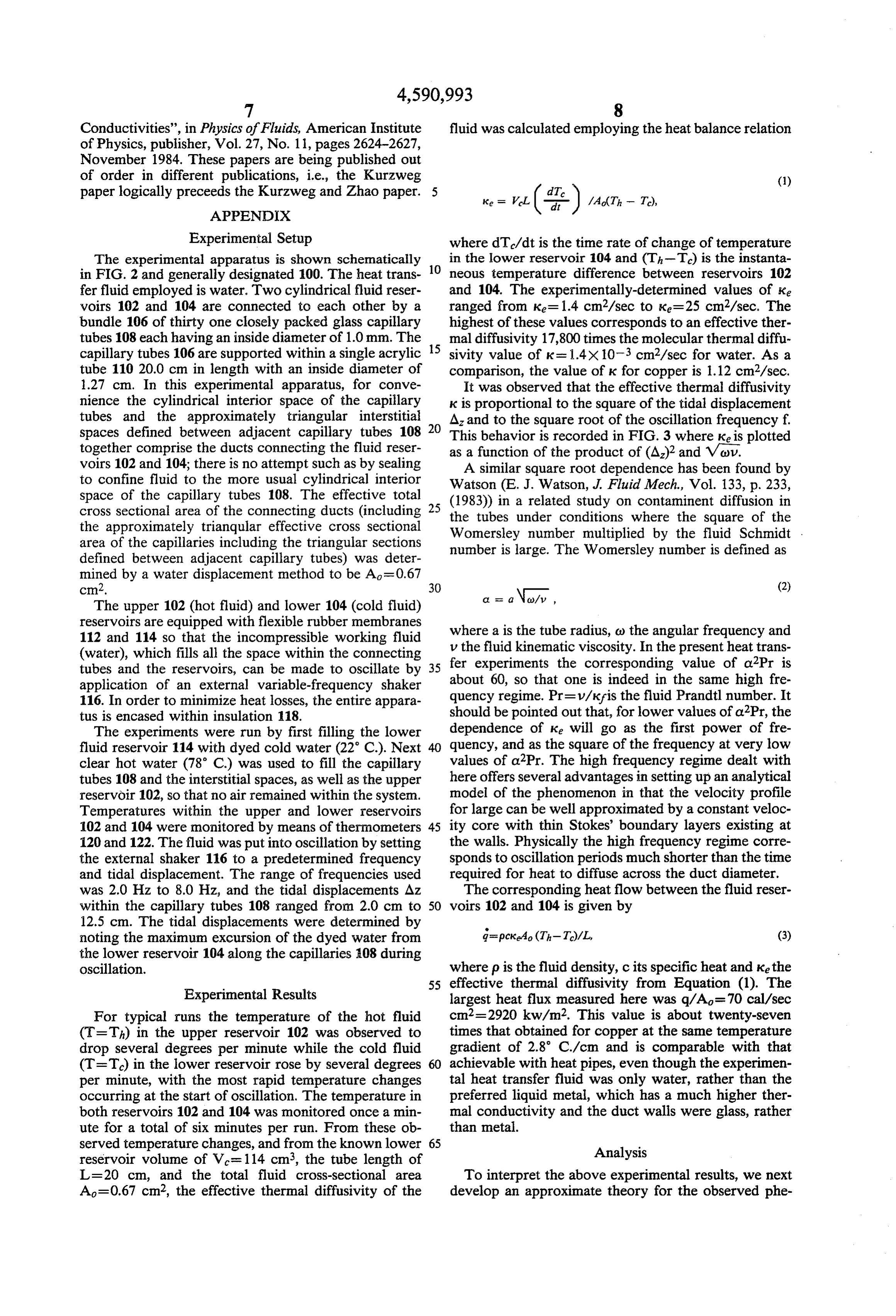
Conductivities', in Physics of Fluids, American Institute fluid was calculated employing the heat balance relation of Physics, publisher, Vol. 27, No. 11, pages 2624-2627,
November 1984. These papers are being published out of order in different publications, i.e., the Kurzweg (1) paper logically preceeds the Kurzweg and Zhao paper. Ke = VeL
APPENDIX
Experimental Setup where dT/dt is the time rate of change of temperature The experimental apparatus is shown schematically 10 in the lower reservoir 104 and (Th-T) is the instanta in FIG. 2 and generally designated 100. The heat trans neous temperature difference between reservoirs 102 fer fluid employed is water. Two cylindrical fluid reser and 104. The experimentally-determined values of ke voirs 102 and 104 are connected to each other by a ranged from Ke=1.4 cm2/sec to ke=25 cm2/sec. The bundle 106 of thirty one closely packed glass capillary highest of these values corresponds to an effective ther tubes 108 each having an inside diameter of 1.0 mm. The 15 mal diffusivity 17,800 times the molecular thermal diffu capillary tubes 106 are supported within a single acrylic sivity value of k = 1.4x 10⁻³ cm2/sec for water. As a tube 110 20.0 cm in length with an inside diameter of comparison, the value of k for copper is 1.12 cm2/sec. 1.27 cm. In this experimental apparatus, for conve It was observed that the effective thermal diffusivity nience the cylindrical interior space of the capillary k is proportional to the square of the tidal displacement tubes and the approximately triangular interstitial A and to the square root of the oscillation frequency f. spaces defined between adjacent capillary tubes 108 20 This behavior is recorded in FIG. 3 where keis plotted together comprise the ducts connecting the fluid reser as a function of the product of (A2)2 and Vou. voirs 102 and 104; there is no attempt such as by sealing A similar square root dependence has been found by to confine fluid to the more usual cylindrical interior Watson (E. J. Watson, J. Fluid Mech., Vol. 133, p. 233, space of the capillary tubes 108. The effective total (1983) in a related study on contaminent diffusion in cross sectional area of the connecting ducts (including 25 the approximately trianqular effective cross sectional the tubes under conditions where the square of the area of the capillaries including the triangular sections Womersley number multiplied by the fluid Schmidt . defined between adjacent capillary tubes) was deter number is large. The Womersley number is defined as mined by a water displacement method to be A=0.67 cm2. 30 (2)
The upper 102 (hot fluid) and lower 104 (cold fluid) reservoirs are equipped with flexible rubber membranes where a is the tube radius, c) the angular frequency and 112 and 114 so that the incompressible working fluid v the fluid kinematic viscosity. In the present heat trans (water), which fills all the space within the connecting fer experiments the corresponding value of a 2Pr is tubes and the reservoirs, can be made to oscillate by 35 application of an external variable-frequency shaker about 60, so that one is indeed in the same high fre 116. In order to minimize heat losses, the entire appara quency regime. Pr=v/k?is the fluid Prandtl number. It tus is encased within insulation 118. should be pointed out that, for lower values of aPr, the The experiments were run by first filling the lower dependence of Ke will go as the first power of fre fluid reservoir 114 with dyed cold water (22 C.). Next quency, and as the square of the frequency at very low clear hot water (78° C) was used to fill the capillary values of a2Pr. The high frequency regime dealt with tubes 108 and the interstitial spaces, as well as the upper here offers several advantages in setting up an analytical reservoir 102, so that no air remained within the system. model of the phenomenon in that the velocity profile Temperatures within the upper and lower reservoirs for large can be well approximated by a constant veloc 102 and 104 were monitored by means of thermometers 45 ity core with thin Stokes' boundary layers existing at 120 and 122. The fluid was put into oscillation by setting the walls. Physically the high frequency regime corre the external shaker 116 to a predetermined frequency sponds to oscillation periods much shorter than the time and tidal displacement. The range of frequencies used required for heat to diffuse across the duct diameter. was 2.0 Hz to 8.0 Hz, and the tidal displacements Az The corresponding heat flow between the fluid reser within the capillary tubes 108 ranged from 2.0 cm to 50 voirs 102 and 104 is given by 12.5 cm. The tidal displacements were determined by noting the maximum excursion of the dyed water from d=pckeao (Th-T)/L, (3) the lower reservoir 104 along the capillaries 08 during oscillation. where p is the fluid density, c its specific heat and ke the 55 effective thermal diffusivity from Equation (1). The
Experimental Results largest heat flux measured here was q/A=70 cal/sec For typical runs the temperature of the hot fluid cm2=2920 kw/m2. This value is about twenty-seven (T=Th) in the upper reservoir 102 was observed to times that obtained for copper at the same temperature drop several degrees per minute while the cold fluid gradient of 2.8 C./cm and is comparable with that (T=T) in the lower reservoir rose by several degrees achievable with heat pipes, even though the experimen per minute, with the most rapid temperature changes tal heat transfer fluid was only water, rather than the occurring at the start of oscillation. The temperature in preferred liquid metal, which has a much higher ther both reservoirs 102 and 104 was monitored once a min mal conductivity and the duct walls were glass, rather ute for a total of six minutes per run. From these ob than metal.
served temperature changes, and from the known lower 65 Analysis reservoir volume of Ve=114 cm3, the tube length of
L=20 cm, and the total fluid cross-sectional area To interpret the above experimental results, we next A=0.67 cm2, the effective thermal diffusivity of the develop an approximate theory for the observed phe
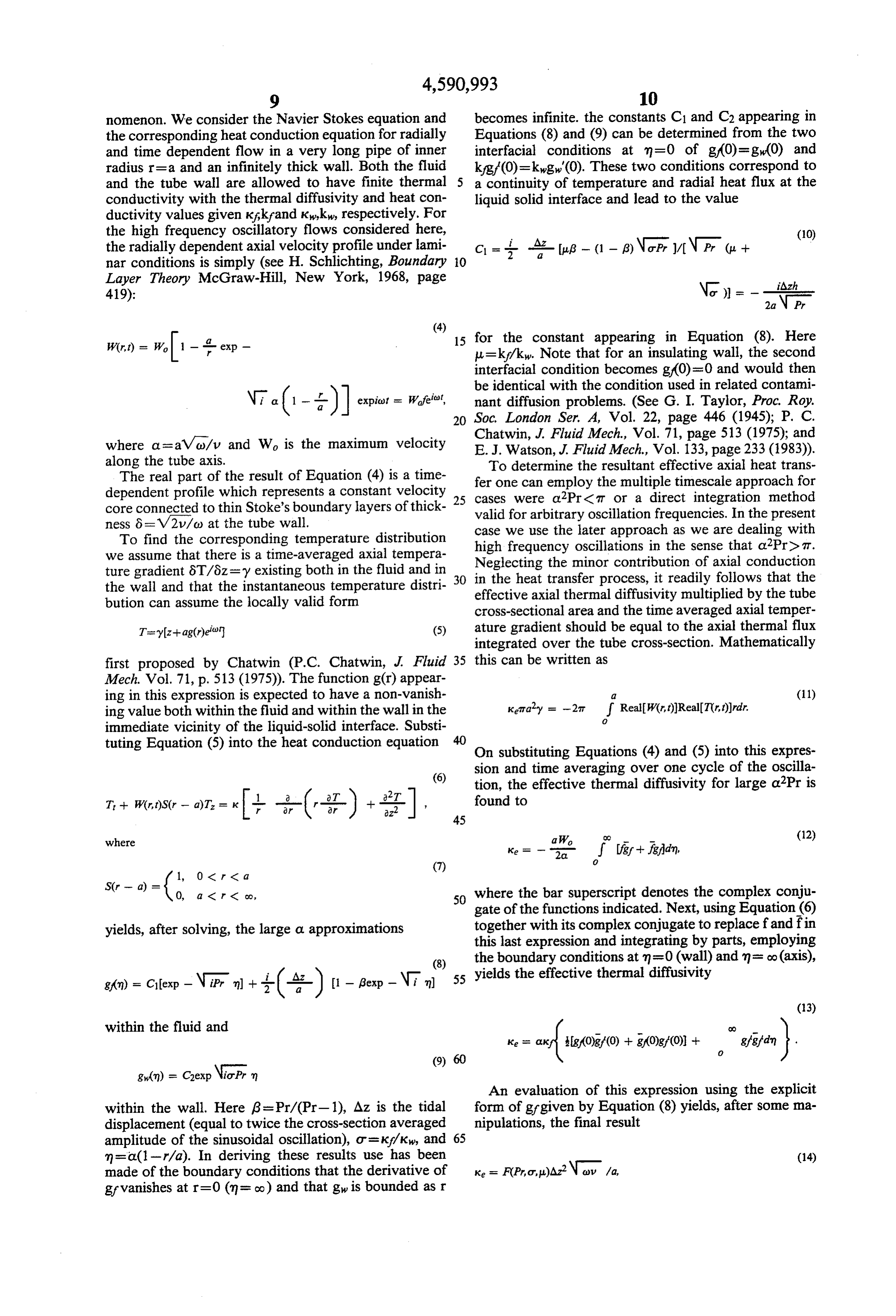
Page 10
nomenon. We consider the Navier Stokes equation and becomes infinite. the constants C1 and C2 appearing in the corresponding heat conduction equation for radially Equations (8) and (9) can be determined from the two and time dependent flow in a very long pipe of inner interfacial conditions at m=0 of g(0)= g(0) and radius r=a and an infinitely thick wall. Both the fluid k/gf(0)=kwgw'(0). These two conditions correspond to and the tube wall are allowed to have finite thermal 5 a continuity of temperature and radial heat flux at the conductivity with the thermal diffusivity and heat con liquid solid interface and lead to the value ductivity values given Kakrand Kwkw, respectively. For the high frequency oscillatory flows considered here, (10) the radially dependent axial velocity profile under lami C = } Af tag - (1 - B) \o Pr/\Pr( + nar conditions is simply (see H. Schlichting, Boundary O
Layer Theory McGraw-Hill, New York, 1968, page 419): Nor)) = --2 \p, all
15 for the constant appearing in Equation (8). Here
W(r,t) = W. - exp - u=kf/kw. Note that for an insulating wall, the second interfacial condition becomes g(0)=0 and would then be identical with the condition used in related contami \ o ( --- i) expiot = Wife, nant diffusion problems. (See G. I. Taylor, Proc. Roy.
where a=aVo/v and Wa is the maximum velocity Chatwin, J. Fluid Mech., Vol. 71, page 513 (1975); and
along the tube axis. To determine the resultant effective axial heat trans The real part of the result of Equation (4) is a time fer one can employ the multiple timescale approach for dependent profile which represents a constant velocity 25 cases were a2Pr< 7T or a direct integration method core connected to thin Stoke's boundary layers of thick valid for arbitrary oscillation frequencies. In the present ness 8 = V2/o) at the tube wall. case we use the later approach as we are dealing with To find the corresponding temperature distribution high frequency oscillations in the sense that a 2Pre it. we assume that there is a time-averaged axial tempera Neglecting the minor contribution of axial conduction ture gradient 8T/6z=y existing both in the fluid and in 30 in the heat transfer process, it readily follows that the the wall and that the instantaneous temperature distri effective axial thermal diffusivity multiplied by the tube bution can assume the locally valid form cross-sectional area and the time averaged axial temper T=yz+ag(r)e (5) ature gradient should be equal to the axial thermal flux integrated over the tube cross-section. Mathematically first proposed by Chatwin (P.C. Chatwin, J. Fluid this can be written as
ing in this expression is expected to have a non-vanish al (11) ing value both within the fluid and within the wall in the Keita'y = -2T f RealW(r,t))Real(T(r,t))rdr.
immediate vicinity of the liquid-solid interface. Substi tuting Equation (5) into the heat conduction equation On substituting Equations (4) and (5) into this expres
sion and time averaging over one cycle of the oscilla
tion, the effective thermal diffusivity for large a2Pr is
T -- W(r,t)S(r - a)T = --(-t-) -- 222 y found to
where a W. (12)
0, a < r < co, 50 where the bar superscript denotes the complex conju gate of the functions indicated. Next, using Equation (6) yields, after solving, the large a. approximations together with its complex conjugate to replace f and fin this last expression and integrating by parts, employing (8) the boundary conditions at m=0 (wall) and m= o(axis), g(n) = C(exp-NiPrn) + 4-(--) (1 - Bexp - Ni n) 55 yields the effective thermal diffusivity
within the fluid and
An evaluation of this expression using the explicit within the wall. Here 6=Pr/(Pr-1), Az is the tidal form of grgiven by Equation (8) yields, after some ma displacement (equal to twice the cross-section averaged nipulations, the final result amplitude of the sinusoidal oscillation), o=kp/k, and 65 m= a(1-r/a). In deriving these results use has been (14) made of the boundary conditions that the derivative of Ke = F(Prou)Az’ Nov/a, gf vanishes at r=0 (m = Co) and that gw is bounded as r
Page 11
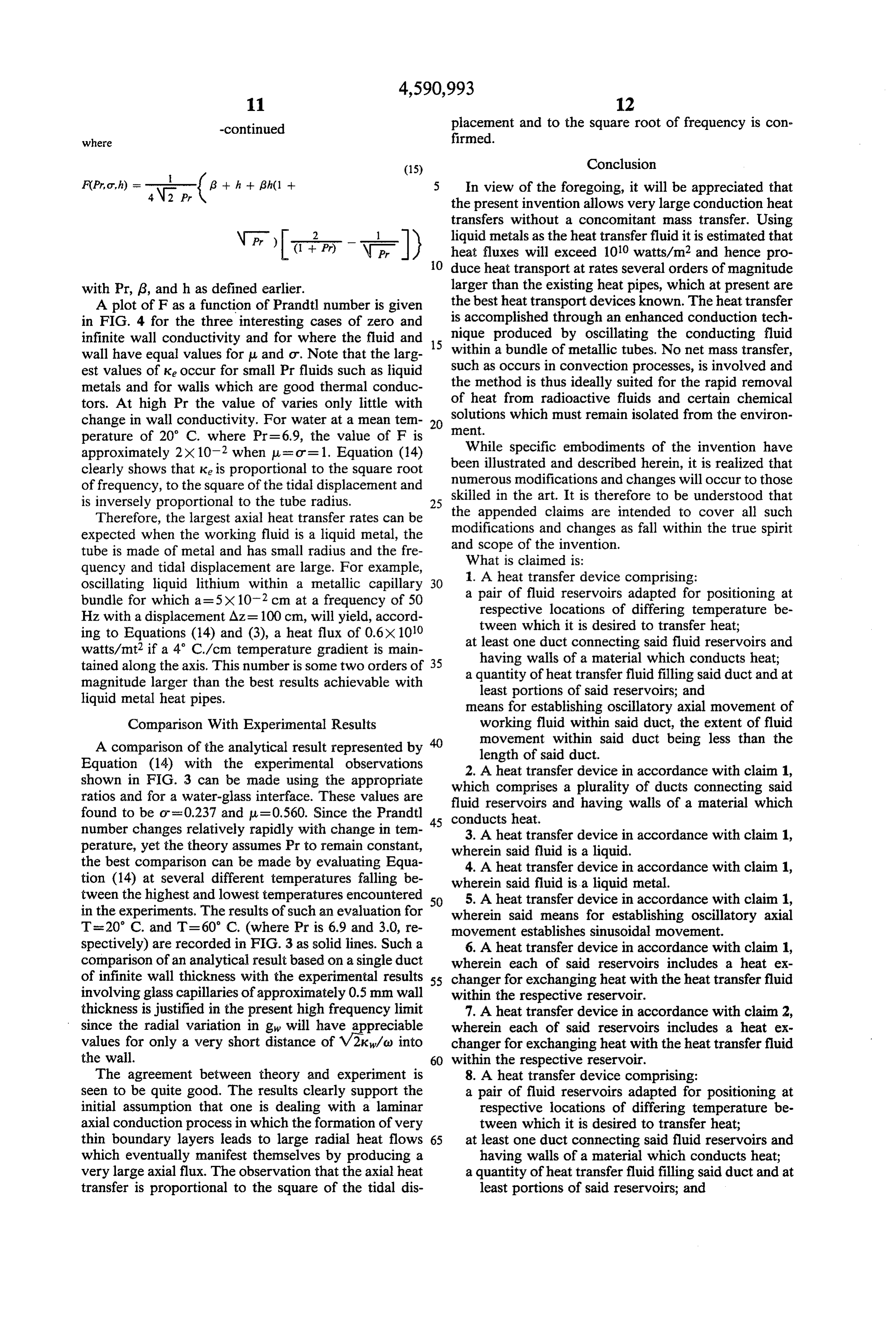
-continued placement and to the square root of frequency is con where firmed.
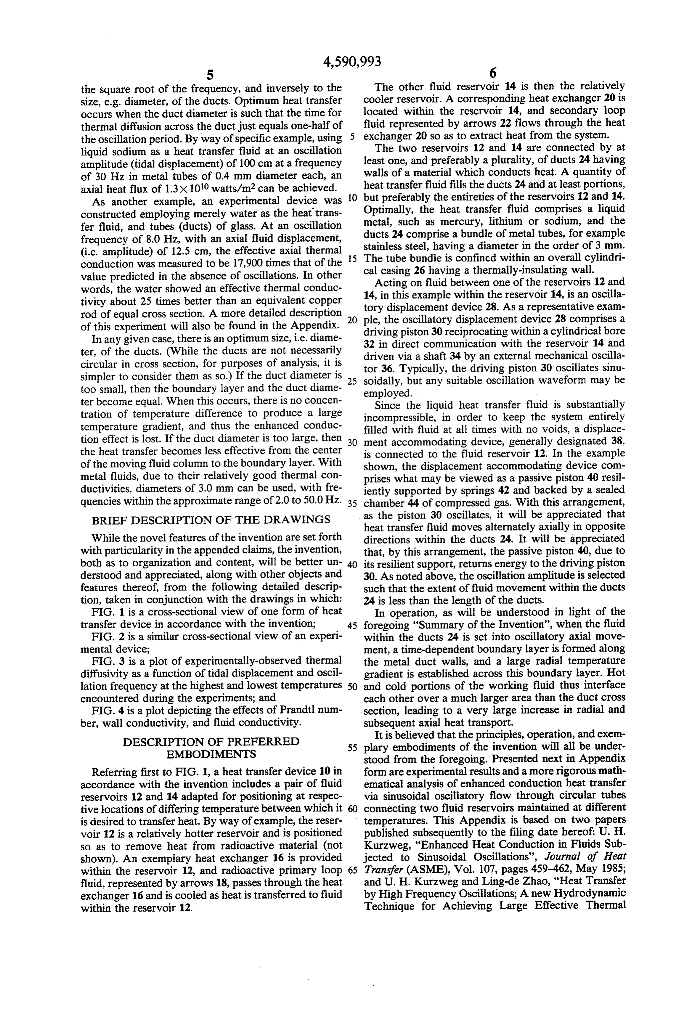
4\2 Pr ( In view of the foregoing, it will be appreciated that the present invention allows very large conduction heat transfers without a concomitant mass transfer. Using \ liquid metals as the heat transfer fluid it is estimated that Pr G +2 P) \ , D O heat fluxes will exceed 1010 watts/m2 and hence pro duce heat transport at rates several orders of magnitude with Pr, 18, and h as defined earlier. larger than the existing heat pipes, which at present are A plot of F as a function of Prandtl number is given the best heat transport devices known. The heat transfer in FIG. 4 for the three interesting cases of zero and is accomplished through an enhanced conduction tech infinite wall conductivity and for where the fluid and 15 nique produced by oscillating the conducting fluid wall have equal values for u and ot. Note that the larg within a bundle of metallic tubes. No net mass transfer, est values of ke occur for small Pr fluids such as liquid such as occurs in convection processes, is involved and metals and for walls which are good thermal conduc the method is thus ideally suited for the rapid removal of heat from radioactive fluids and certain chemical tors. At high Pr the value of varies only little with solutions change in wall conductivity. For water at a mean tem 20 ent. which must remain isolated from the environ perature of 20° C. where Pr=6.9, the value of F is approximately 2X 10² when u = or=1. Equation (14) While specific embodiments of the invention have clearly shows that ke is proportional to the square root been illustrated and described herein, it is realized that numerous modifications and changes will occur to those of frequency, to the square of the tidal displacement and skilled is inversely proportional to the tube radius. 25 in the art. It is therefore to be understood that
Therefore, the largest axial heat transfer rates can be the appended claims are intended to cover all such expected when the working fluid is a liquid metal, the modifications and changes as fall within the true spirit tube is made of metal and has small radius and the fre and scope of the invention.
quency and tidal displacement are large. For example, What is claimed is:
oscillating liquid lithium within a metallic capillary 30 a1. pair A heat transfer device comprising: of fluid reservoirs adapted for positioning at bundle for which a-5X 10⁻² cm at a frequency of 50 respective locations of differing temperature be Hz with a displacement Az= 100 cm, will yield, accord tween which it is desired to transfer heat; ing to Equations (14) and (3), a heat flux of 0.6X 100 at least one duct connecting said fluid reservoirs and watts/mt2 if a 4° C./cm temperature gradient is main having walls of a material which conducts heat; tained along the axis. This number is some two orders of 35 a quantity of heat transfer fluid filling said duct and at magnitude larger than the best results achievable with least portions of said reservoirs; and liquid metal heat pipes. means for establishing oscillatory axial movement of Comparison With Experimental Results working fluid within said duct, the extent of fluid A comparison of the analytical result represented by movement within said duct being less than the Equation (14) with the experimental observations length of said duct.
shown in FIG. 3 can be made using the appropriate which comprises A heat transfer device in accordance with claim 1, ratios and for a water-glass interface. These values are fluid reservoirs and a plurality of ducts connecting said having walls of a material which found to be os-0.237 and u = 0.560. Since the Prandtl 45 conducts heat.
number changes relatively rapidly with change in ten 3. A heat transfer device in accordance with claim 1, perature, yet the theory assumes Pr to remain constant, wherein said fluid is a liquid.
the best comparison can be made by evaluating Equa 4. A heat transfer device in accordance with claim 1, tion (14) at several different temperatures falling be wherein said fluid is a liquid metal. tween the highest and lowest temperatures encountered 50 5. A heat transfer device in accordance with claim 1, in the experiments. The results of such an evaluation for wherein said means for establishing oscillatory axial T= 20° C. and T=60° C. (where Pr is 6.9 and 3.0, re movement establishes sinusoidal movement. spectively) are recorded in FIG.3 as solid lines. Such a 6. A heat transfer device in accordance with claim 1, comparison of an analytical result based on a single duct wherein each of said reservoirs includes a heat ex of infinite wall thickness with the experimental results 55 changer for exchanging heat with the heat transfer fluid involving glass capillaries of approximately 0.5mm wall within the respective reservoir.
thickness is justified in the present high frequency limit 7. A heat transfer device in accordance with claim 2, since the radial variation in gy will have appreciable wherein each of said reservoirs includes a heat ex values for only a very short distance of V2k/o into changer for exchanging heat with the heat transfer fluid the wall. 60 within the respective reservoir. The agreement between theory and experiment is 8. A heat transfer device comprising: seen to be quite good. The results clearly support the a pair of fluid reservoirs adapted for positioning at initial assumption that one is dealing with a laminar respective locations of differing temperature be axial conduction process in which the formation of very tween which it is desired to transfer heat; thin boundary layers leads to large radial heat flows 65 at least one duct connecting said fluid reservoirs and which eventually manifest themselves by producing a having walls of a material which conducts heat; very large axial flux. The observation that the axial heat a quantity of heat transfer fluid filling said duct and at transfer is proportional to the square of the tidal dis least portions of said reservoirs; and
Page 12
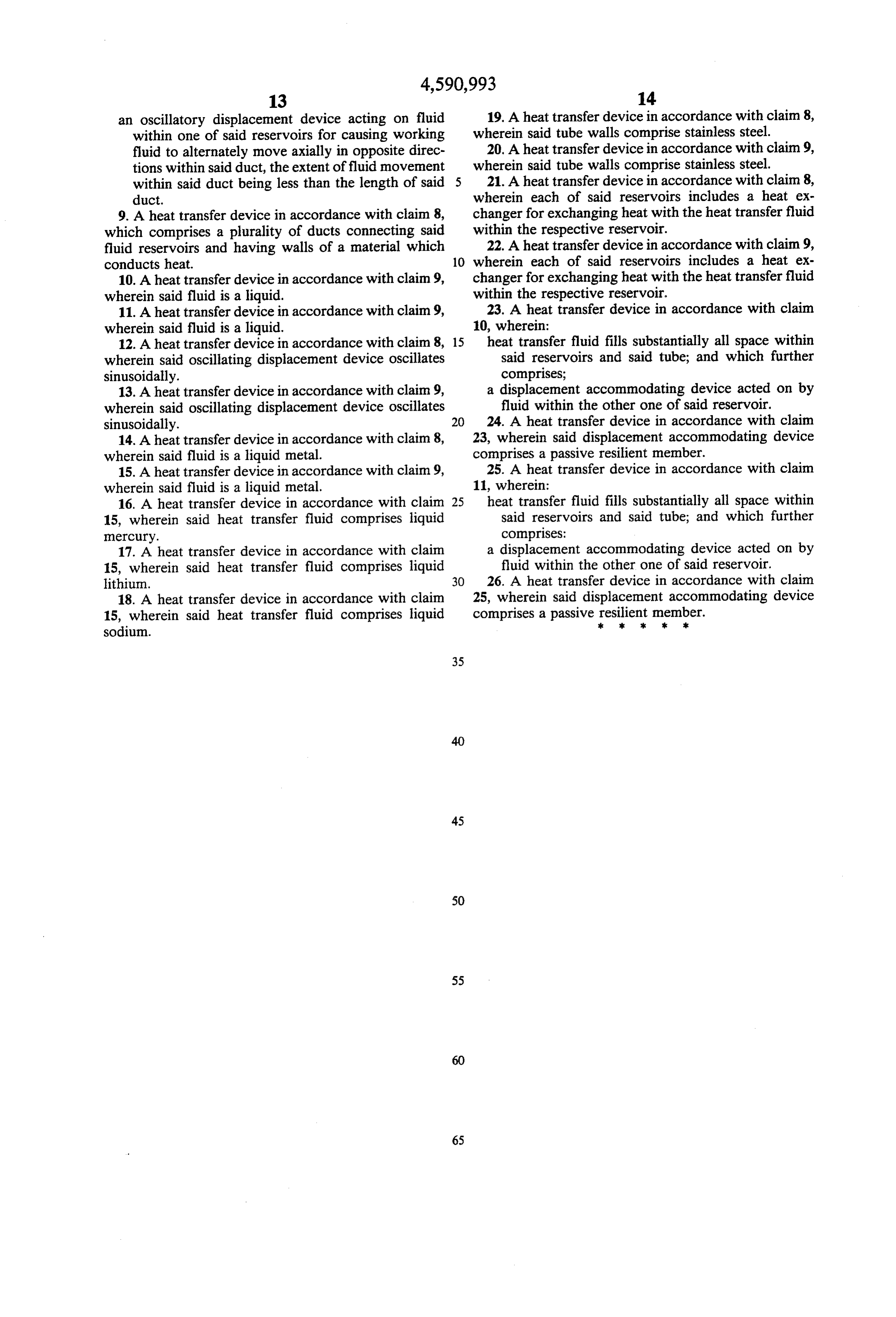
an oscillatory displacement device acting on fluid 19. A heat transfer device in accordance with claim 8, within one of said reservoirs for causing working wherein said tube walls comprise stainless steel. fluid to alternately move axially in opposite direc 20. A heat transfer device in accordance with claim 9, tions within said duct, the extent of fluid movement wherein said tube walls comprise stainless steel. within said duct being less than the length of said 5 21. A heat transfer device in accordance with claim 8, duct. wherein each of said reservoirs includes a heat ex 9. A heat transfer device in accordance with claim 8, changer for exchanging heat with the heat transfer fluid which comprises a plurality of ducts connecting said within the respective reservoir.
fluid reservoirs and having walls of a material which 22. A heat transfer device in accordance with claim 9, conducts heat. 10 wherein each of said reservoirs includes a heat ex 10. A heat transfer device in accordance with claim 9, changer for exchanging heat with the heat transfer fluid wherein said fluid is a liquid. within the respective reservoir. 11. A heat transfer device in accordance with claim 9, 23. A heat transfer device in accordance with claim wherein said fluid is a liquid. 10, wherein:
12. A heat transfer device in accordance with claim 8, 15 heat transfer fluid fills substantially all space within wherein said oscillating displacement device oscillates said reservoirs and said tube; and which further sinusoidally. comprises;
13. A heat transfer device in accordance with claim 9, a displacement accommodating device acted on by wherein said oscillating displacement device oscillates fluid within the other one of said reservoir. sinusoidally. 20 24. A heat transfer device in accordance with claim 14. A heat transfer device in accordance with claim 8, 23, wherein said displacement accommodating device wherein said fluid is a liquid metal. comprises a passive resilient member. 15. A heat transfer device in accordance with claim 9, 25. A heat transfer device in accordance with claim wherein said fluid is a liquid metal. 11, wherein:
16. A heat transfer device in accordance with claim 25 heat transfer fluid fills substantially all space within 15, wherein said heat transfer fluid comprises liquid said reservoirs and said tube; and which further mercury. comprises:
17. A heat transfer device in accordance with claim a displacement accommodating device acted on by 15, wherein said heat transfer fluid comprises liquid fluid within the other one of said reservoir. lithium. 30 26. A heat transfer device in accordance with claim 18. A heat transfer device in accordance with claim 25, wherein said displacement accommodating device 15, wherein said heat transfer fluid comprises liquid comprises a passive skresilient
member.
sodium.
Provenance
- Collection
- Cited prior art
- Original PDF
- patentimages.storage.googleapis.com →
- Filed
- 1984-10-23
- Pages
- 12
- Method
- pdftotext (the PDF's own text layer) + pdftoppm 300dpi page scans
- Source
- Google Patents bibliographic record
- Granted
- 1986-05-27
- Inventors
- Ulrich H. Kurzweg; University of Florida
- Transcribed from
- patentimages.storage.googleapis.com →