patent · US4187686
Power generator utilizing elevation-temperature differential
12 February 1980
Page 1 — bibliographic record
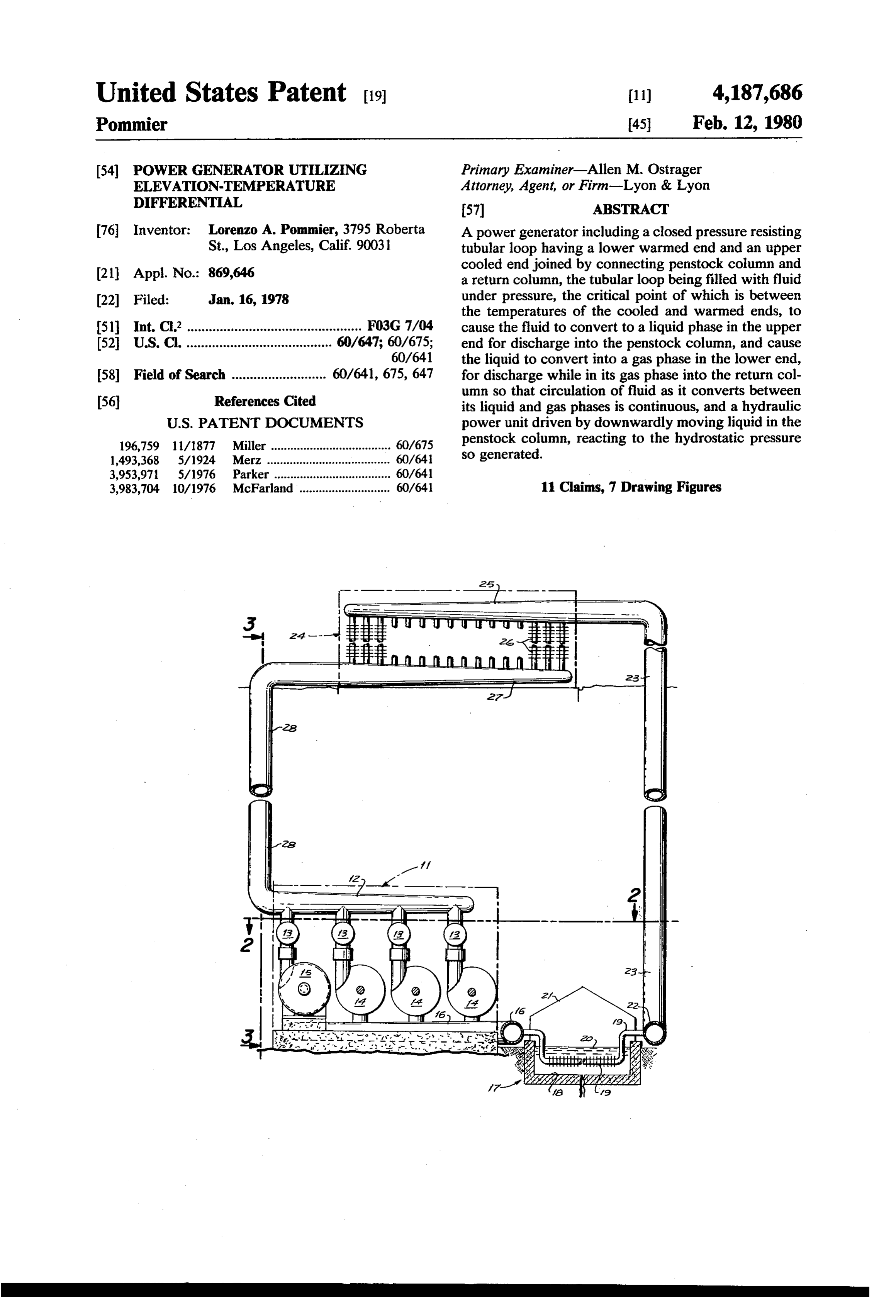
United States Patent (19) 11) 4,187,686 Pommier 45 Feb. 12, 1980 (54) POWER GENERATOR. UTILIZING Primary Examiner-Allen M. Ostrager ELEVATION-TEMPERATURE Attorney, Agent, or Firm-Lyon & Lyon OFFERENTAL 57 ABSTRACT 76 Inventor: Lorenzo A. Pommier, 3795 Roberta A power generator including a closed pressure resisting St., Los Angeles, Calif. 90031 tubular loop having a lower warmed end and an upper 21 Appl. No.: 869,646 cooled end joined by connecting penstock column and a return column, the tubular loop being filled with fluid (22 Filed: Jan. 16, 1978 under pressure, the critical point of which is between the temperatures of the cooled and warmed ends, to 51 int. C.’................................................ F03G 7/04 cause the fluid to convert to a liquid phase in the upper 52 U.S. C. ........................................ 60/647; 60/675; end for discharge into the penstock column, and cause 60/641 the liquid to convert into a gas phase in the lower end, 58) Field of Search .......................... 60/641, 675, 647 for discharge while in its gas phase into the return col umn so that circulation of fluid as it converts between 56 References Cited its liquid and gas phases is continuous, and a hydraulic
196,759 1 1/1877 Miller ..................................... 60/675 penstock column, reacting to the hydrostatic pressure 1,493,368 5/1924. Merz ... ... 60/64 so generated.
3,953,971 5/1976 Parker ..... ... 60/641 3,983,704 10/1976 McFarland............................ 60/641 11 Claims, 7 Drawing Figures
Page 2
Drawing sheet — no readable text.
Page 3
Drawing sheet — no readable text.
Page 4
relatively high pressure. The loop includes an upper end
POWER GENERATOR. UTILIZING 2 and a lower end 3 connected by a penstock column 4 ELEVATION-TEMPERATURE DIFFERENTAL and return column 5.
The pressure loop contains a fluid having a liquid
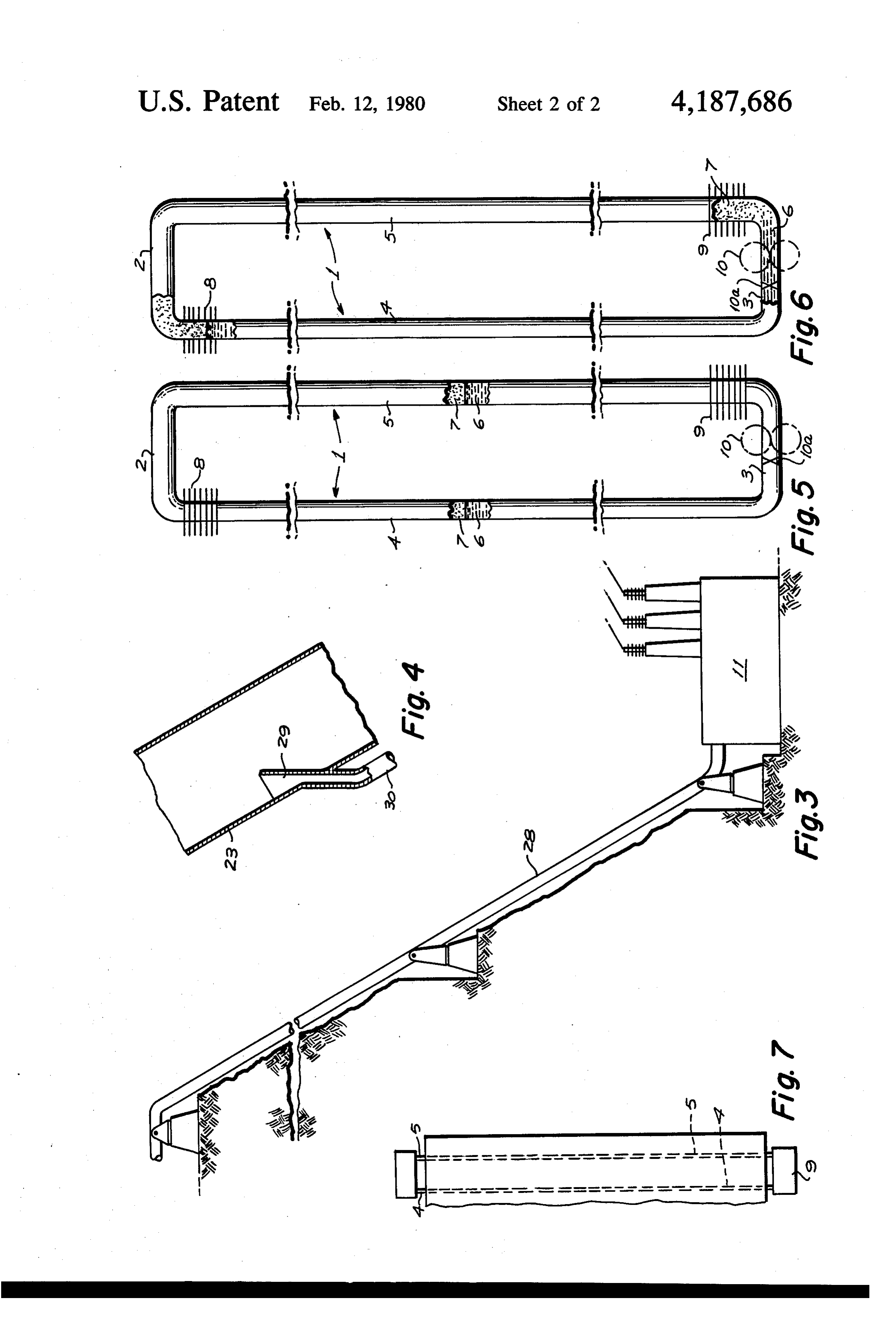
BACKGROUND AND SUMMARY 5 phase indicated by 6 and a gaseous phase indicated by 7. Power generators utilizing, for example, temperature At or adjacent the upper end of the penstock column 4 differences between two natural locations such as vol is a condensing heat exchanger 8; that is, the heat ex cano or naturally heated underground water, or differ changer 8 is subjected to external cooling for the pur ent temperatures at different ocean depths, have been in pose of converting the fluid to its liquid phase 6. At or existence. The present invention utilizes the difference O adjacent the lower end of the return column 5 there is between ambient temperatures at different elevations, provided an evaporating heat exchanger 9; that is, ex the difference between daytime and nighttime tempera ternal heat is supplied through the heat exchanger to ture, or generally low grade heat sources. change the fluid from its liquid phase 6 to its gaseous The present invention also utilizes large differences in 15 phase 7.
elevation to obtain an increase in the availability of the At the lower end exposed to the fluid in its liquid energy contained in a working medium. The scale of phase is a hydraulic power unit 10, preceded by inlet this invention is large. Column heights of several hun valve 13.
dred meters, or even several thousand meters are re quired to efficiently utilize temperature differentials STARTING PHASE commonly found in nature. As the scale is large, so is Assume a condition, such as may atypically be the the power output potential. Megawatt outputs would be case if the temperature at the lower level 3 is the same typical of a practical installation. These considerations as the temperature at the upper level 2. This is the con are summarized in the following objects:
First, to provide a power generator wherein a pres dition represented in FIG. 5. The columns 4 and 5 are occupied by a medium (gasliquid) which has been sure resisting closed tubular loop is subjected to ambient 25 chosen to have its critical temperature at or near the temperatures to establish an upper cooled end and a lower level 3 temperature. Such a medium may be car lower heated end joined by a penstock column and a bon dioxide (CO2) but other media are not hereby ex return column, the closed loop containing a fluid under pressure, having a critical temperature between the cluded. Carbon dioxide has a critical temperature of 31.1° C. ambient temperatures at the upper and lower ends, 30 Assuming whereby the fluid condenses at the upper end for down C. and thethe temperature at the lower end 3 to be 31.1 temperature at the upper end 2 to be, atypi ward flow in liquid phase through the penstock column cally, the same, and evaporates at the lower end for upward flow in the fluid mediumthen both columns 4 and 5 will contain at the bottom 3 in its liquid state, but gaseous phase through the return column, the penstock the fluid medium gradually decreases in density toward column having one or more generators driven by the 35 downwardly flowing fluid in its liquid phase. the top where both columns become gaseous. Both Second, to provide a power generator, as indicated in columns will, of course, exhibit the same relative densi the preceding object, wherein heat exchangers are dis ties and will generate the same pressure at the bottom. Assume that the valve 1.0a is closed and that a rise in posed at the upper and lower ends of the loop and are of temperature such capacity as to maintain an essentially constant at the bottom of column 5 occurs to, say, movement of the fluid through variations in ambient 33 C.; that is, a temperature just above the critical point temperature. for CO2. As heat is added gradually to column 5 by the Third, to provide a power generator, as indicated in heat exchanger 9, the liquid-gas transition zone in col the preceding objects, wherein, but not by way of limi umn 5 gradually falls and the transition zone in column tation, the lower end is a station disposed in a sun heated 45 4 will gradually rise until the fluid medium in column 5 valley and the upper end is a station disposed on a has been completely gasified. Also assume that simulta mountain top. neously the fluid medium entering column 4 is cooled by heat exchanger 8 and the gas-liquid transition zone in
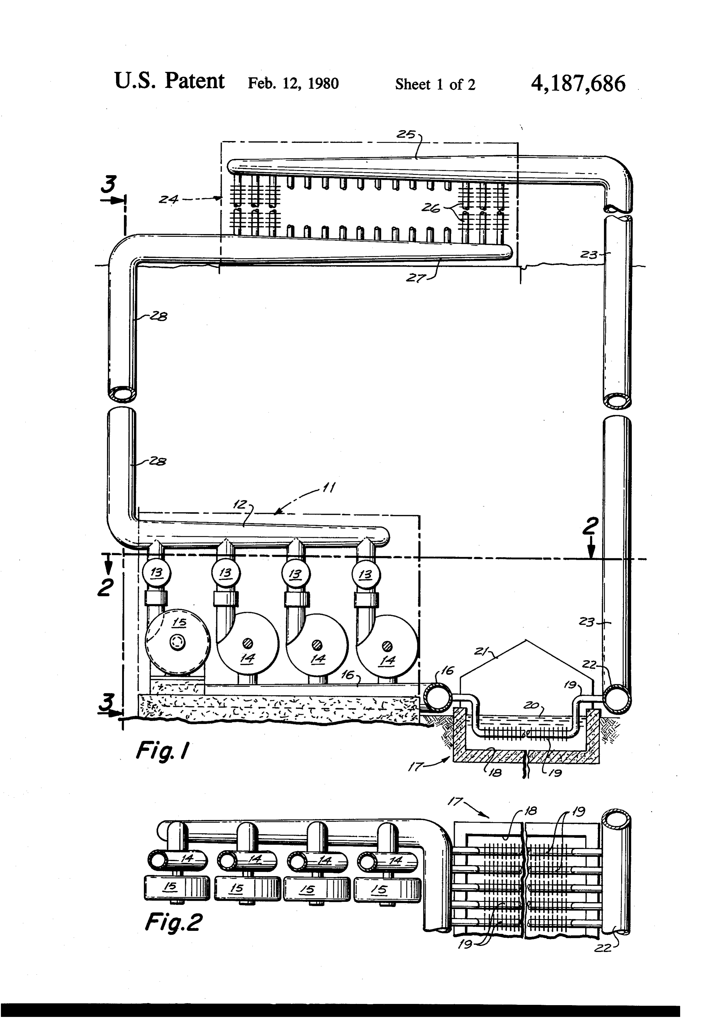
BRIEF DESCRIPTION OF THE FIGURES column 4 reaches the level of heat exchanger 8. This FIG. 1 is a diagrammatical front view of the power 50 ends the starting phase.
generator with portions in section. RUNNING PHASE FIG. 2 is a fragmentary sectional view thereof taken through 2-2 of FIG. 1. Valve 13 is now open imposing upon the hydraulic FIG. 3 is a side view at a reduced scale taken from motor 10 the differential of pressure between columns 4 3-3 of FIG.1. 55 and 5. Responding to this pressure differential, the hy FIG. 4 is a fragmentary sectional view of the pen draulic motor 10 will produce useful work as for exam stock column. . ple electrical energy.
FIGS. 5 and 6 are more simplified diagrammatical The heat necessary to gasify one kilogram of CO2 at views in front aspect, FIG. 5 indicating an initial or 31 C. is 38.2 Kcalories. Thus, for every 38.2. Kcalories balanced condition, and FIG. 6 indicating a power gen of heat supplied at the lower level 3, roughly one kilo erating condition. gram of gasified CO2 will enter column 5. Assume that FIG. 7 is a simplified diagrammatical view of the the hydraulic motor 10 is so regulated as to allow one power generator in association with a tall building. kilogram of the fluid medium to pass for every 38.3 K DETAILED DESCRIPTION calories supplied. Now, as each kilogram of fluid me 65 dium is added to the total content of return column 5, so
Referring first to FIGS. 5 and 6: the power generator does the pressure proportionately increase in column 5 is in the form of a closed pressure loop 1; that is, the except for that amount of material as is condensed out in loop is formed of metal tubing capable of withstanding the heat exchanger 8 and except as heat is absorbed in
Page 5
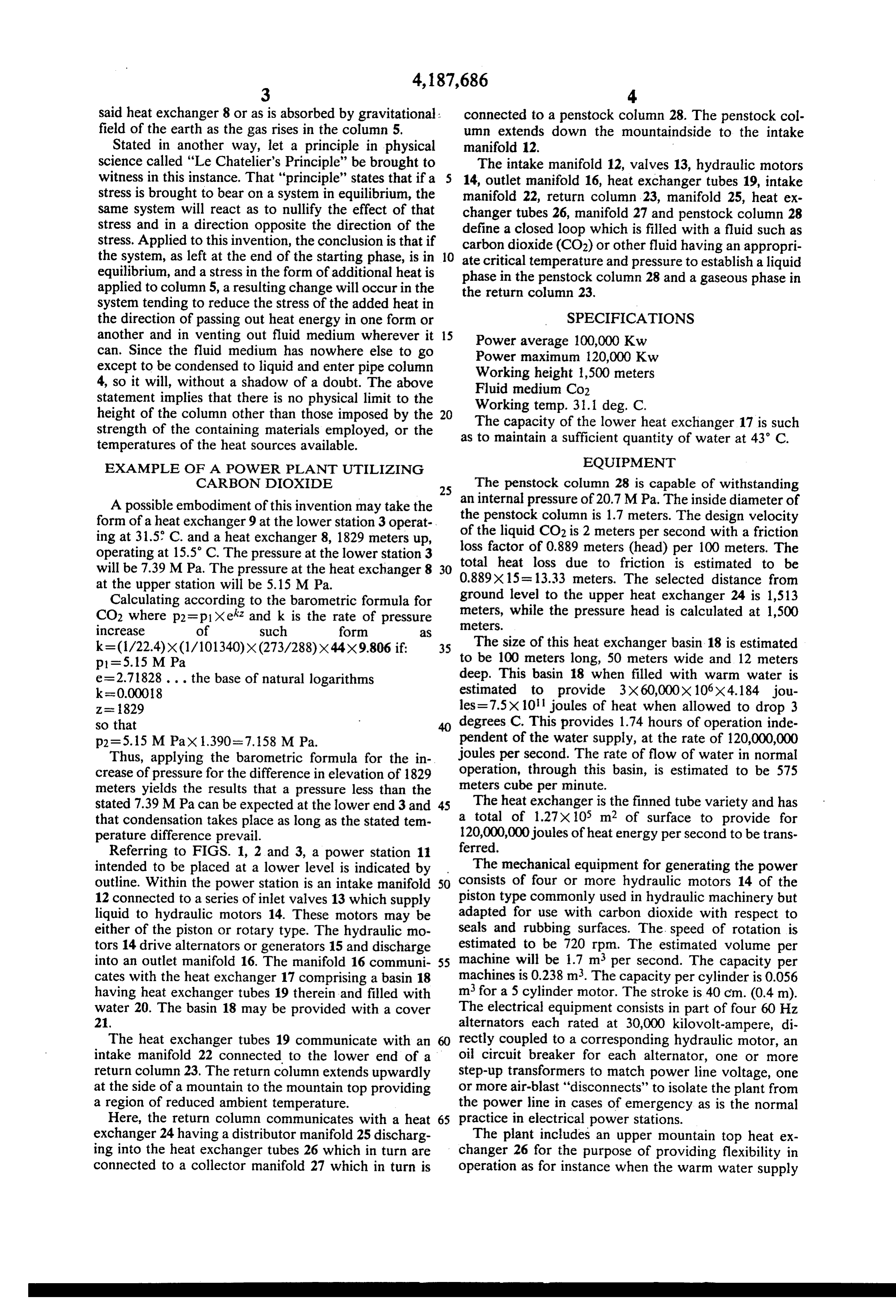
said heat exchanger 8 or as is absorbed by gravitational: connected to a penstock column 28. The penstock col field of the earth as the gas rises in the column 5. umn extends down the mountaindside to the intake Stated in another way, let a principle in physical manifold 12.
science called “Le Chatelier's Principle" be brought to The intake manifold 12, valves 13, hydraulic motors witness in this instance. That "principle" states that if a 5 14, outlet manifold 16, heat exchanger tubes 19, intake stress is brought to bear on a system in equilibrium, the manifold 22, return column 23, manifold 25, heat ex same system will react as to nullify the effect of that changer tubes 26, manifold 27 and penstock column 28 stress and in a direction opposite the direction of the define a closed loop which is filled with a fluid such as stress. Applied to this invention, the conclusion is that if carbon dioxide (CO2) or other fluid having an appropri the system, as left at the end of the starting phase, is in 10 ate critical temperature and pressure to establish a liquid equilibrium, and a stress in the form of additional heat is phase in the penstock column 28 and a gaseous phase in applied to column 5, a resulting change will occur in the the return column 23.
system tending to reduce the stress of the added heat in the direction of passing out heat energy in one form or SPECIFICATIONS another and in venting out fluid medium wherever it 15 Power average 100,000 Kw can. Since the fluid medium has nowhere else to go Power maximum 120,000 Kw except to be condensed to liquid and enter pipe column Working height 1,500 meters 4, so it will, without a shadow of a doubt. The above Fluid medium Co2 statement implies that there is no physical limit to the height of the column other than those imposed by the 20 The capacity of31.1
Working temp.
the deg. C.
lower heat exchanger 17 is such strength of the containing materials employed, or the as to maintain a sufficient quantity of water at 43 C. temperatures of the heat sources available.
EXAMPLE OF A POWER PLANT UTILIZING EQUIPMENT
CARBON DIOXDE 25 The penstock column 28 is capable of withstanding A possible embodiment of this invention may take the an internal pressure of 20.7 MPa. The inside diameter of form of a heat exchanger9 at the lower station 3 operat the penstock column is 1.7 meters. The design velocity ing at 31.5 C. and a heat exchanger 8, 1829 meters up, of the liquid CO2 is 2 meters per second with a friction loss factor of 0.889 meters (head) per 100 meters. The operating at 15.5°C. The pressure at the lower station 3 total heat loss due to friction is estimated to be will be 7.39 MPa. The pressure at the heat exchanger 8 30 0.889X15 = 13.33 meters. The selected distance from at the upper station will be 5.15 MPa.
Calculating according to the barometric formula for ground level to the upper heat exchanger 24 is 1,513 CO2 where p2=p1Xek and k is the rate of pressure meters, meters.
while the pressure head is calculated at 1,500
k= (1/22.4)x(1/101340)x (273/288)X44X9.806 if: 35 The size of this heat exchanger basin 18 is estimated p1=5.15 M Pa to be 100 meters long, 50 meters wide and 12 meters e=2.71828... the base of natural logarithms deep. This basin 18 when filled with warm water is k=0.00018 estimated to provide 3x60,000x 106x4.184 jou Z= 829 les=7.5X 10 joules of heat when allowed to drop 3 so that 40 degrees C. This provides 1.74 hours of operation inde p2=5.15 M Pax 1.390=7.158 MPa. pendent of the water supply, at the rate of 120,000,000 Thus, applying the barometric formula for the in joules per second. The rate of flow of water in normal crease of pressure for the difference in elevation of 1829 operation, through this basin, is estimated to be 575 meters yields the results that a pressure less than the meters cube per minute.
stated 7.39 MPa can be expected at the lower end 3 and 45 The heat exchanger is the finned tube variety and has that condensation takes place as long as the stated tem a total of 1.27x10⁵ m2 of surface to provide for perature difference prevail. 120,000,000 joules of heatenergy per second to be trans Referring to FIGS. 1, 2 and 3, a power station 11 ferred.
intended to be placed at a lower level is indicated by The mechanical equipment for generating the power outline. Within the power station is an intake manifold 50 consists of four or more hydraulic motors 14 of the 12 connected to a series of inlet valves 13 which supply piston type commonly used in hydraulic machinery but liquid to hydraulic motors 14. These motors may be adapted for use with carbon dioxide with respect to either of the piston or rotary type. The hydraulic mo seals and rubbing surfaces. The speed of rotation is tors 14 drive alternators or generators 15 and discharge estimated to be 720 rpm. The estimated volume per into an outlet manifold 16. The manifold 16 communi 55 machine will be 1.7 m per second. The capacity per cates with the heat exchanger 17 comprising a basin 18 machines is 0.238 m. The capacity per cylinder is 0.056 having heat exchanger tubes 19 therein and filled with m for a 5 cylinder motor. The stroke is 40 cm. (0.4 m). water 20. The basin 18 may be provided with a cover The electrical equipment consists in part of four 60 Hz 21. alternators each rated at 30,000 kilovolt-ampere, di The heat exchanger tubes 19 communicate with an rectly coupled to a corresponding hydraulic motor, an intake manifold 22 connected to the lower end of a oil circuit breaker for each alternator, one or more return column 23. The return column extends upwardly step-up transformers to match power line voltage, one at the side of a mountain to the mountain top providing or more air-blast "disconnects' to isolate the plant from a region of reduced ambient temperature. the power line in cases of emergency as is the normal Here, the return column communicates with a heat 65 practice in electrical power stations. exchanger 24 having a distributor manifold 25 discharg The plant includes an upper mountain top heat ex ing into the heat exchanger tubes 26 which in turn are changer 26 for the purpose of providing flexibility in connected to a collector manifold 27 which in turn is operation as for instance when the warm water supply
Page 6
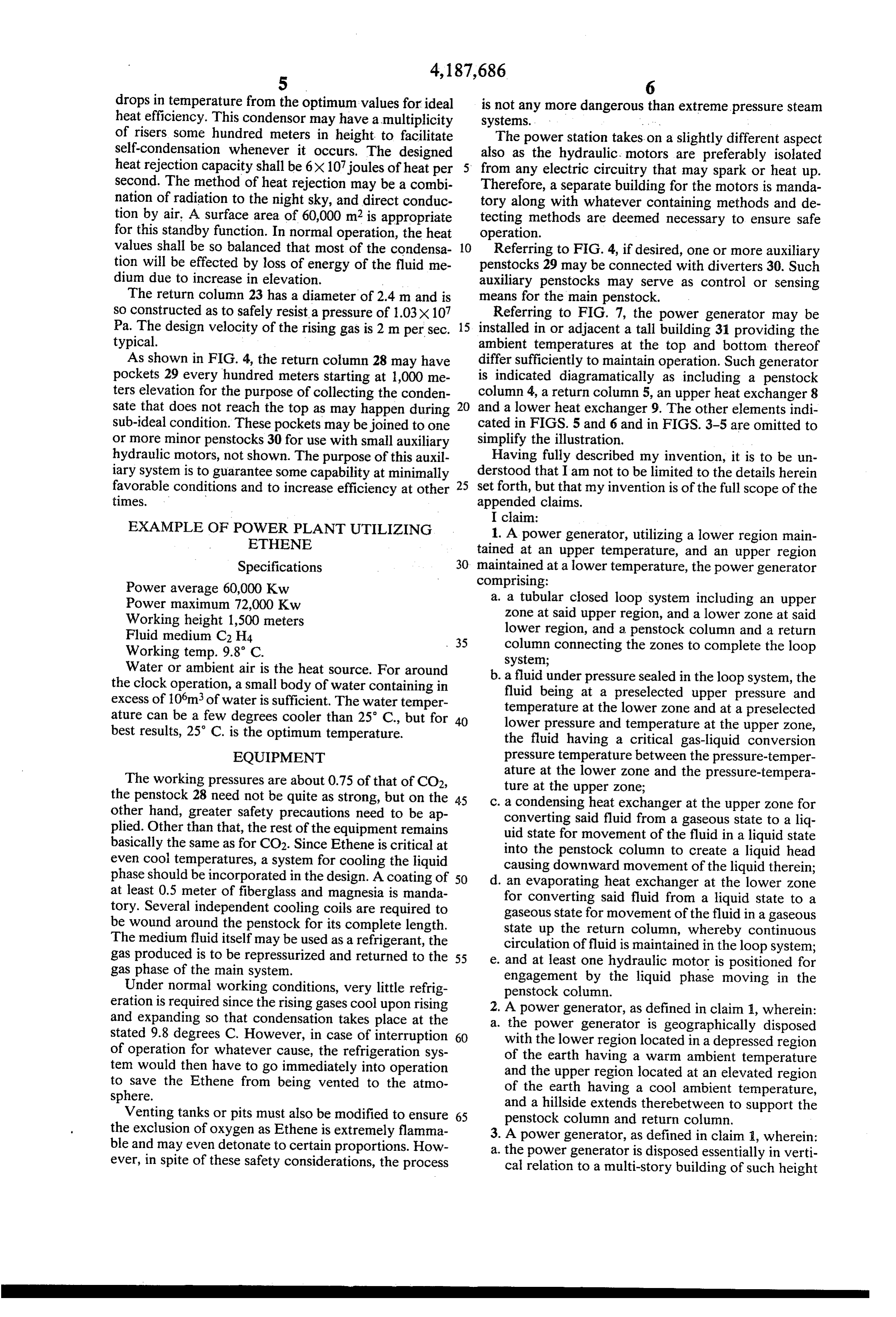
drops in temperature from the optimum values for ideal is not any more dangerous than extreme pressure steam heat efficiency. This condensor may have a multiplicity systems.
of risers some hundred meters in height to facilitate The power station takes on a slightly different aspect self-condensation whenever it occurs. The designed also as the hydraulic motors are preferably isolated heat rejection capacity shall be 6x10⁷ joules of heat per from any electric circuitry that may spark or heat up. Second. The method of heat rejection may be a combi Therefore, a separate building for the motors is manda nation of radiation to the night sky, and direct conduc tory along with whatever containing methods and de tion by air. A surface area of 60,000 m2 is appropriate tecting methods are deemed necessary to ensure safe for this standby function. In normal operation, the heat operation.
values shall be so balanced that most of the condensa 10 Referring to FIG. 4, if desired, one or more auxiliary tion will be effected by loss of energy of the fluid me penstocks 29 may be connected with diverters 30. Such dium due to increase in elevation. auxiliary penstocks may serve as control or sensing The return column 23 has a diameter of 2.4 m and is means for the main penstock.
so constructed as to safely resist a pressure of 1.03X10⁷ Referring to FIG. 7, the power generator may be Pa. The design velocity of the rising gas is 2 m per sec. 15 installed in or adjacent a tall building 31 providing the typical. ambient temperatures at the top and bottom thereof As shown in FIG. 4, the return column 28 may have differ sufficiently to maintain operation. Such generator pockets 29 every hundred meters starting at 1,000 me is indicated diagramatically as including a penstock ters elevation for the purpose of collecting the conden column 4, a return column 5, an upper heat exchanger 8 sate that does not reach the top as may happen during 20 and a lower heat exchanger 9. The other elements indi sub-ideal condition. These pockets may be joined to one cated in FIGS. 5 and 6 and in FIGS. 3-5 are omitted to or more minor penstocks 30 for use with small auxiliary simplify the illustration.
hydraulic motors, not shown. The purpose of this auxil Having fully described my invention, it is to be un iary system is to guarantee some capability at minimally derstood that I am not to be limited to the details herein favorable conditions and to increase efficiency at other 25 set forth, but that my invention is of the full scope of the times. appended claims.
I claim:
EXAMPLE OF POWER PLANT UTILIZING 1. A power generator, utilizing a lower region main ETHENE tained at an upper temperature, and an upper region Specifications 30 maintained at a lower temperature, the power generator Power average 60,000 Kw comprising:
Power maximum 72,000 Kw a. a tubular closed loop system including an upper Working height 1,500 meters zone at said upper region, and a lower zone at said Fluid medium C2H4 lower region, and a penstock column and a return Working temp. 9.8 C. 35 column connecting the zones to complete the loop system;
Water or ambient air is the heat source. For around . a fluid under pressure sealed in the loop system, the the clock operation, a small body of water containing in fluid being at a preselected upper pressure and excess of 10°m of water is sufficient. The water temper temperature at the lower zone and at a preselected ature can be a few degrees cooler than 25 C., but for lower pressure and temperature at the upper zone, best results, 25 C. is the optimum temperature. the fluid having a critical gas-liquid conversion EQUIPMENT pressure temperature between the pressure-temper The working pressures are about 0.75 of that of CO2, ature at the lower zone and the pressure-tempera the penstock 28 need not be quite as strong, but on the 45 ture at the upper zone;
other hand, greater safety precautions need to be ap . a condensing heat exchanger at the upper zone for plied. Other than that, the rest of the equipment remains converting said fluid from a gaseous state to a liq basically the same as for CO2. Since Ethene is critical at uid state for movement of the fluid in a liquid state even cool temperatures, a system for cooling the liquid into the penstock column to create a liquid head phase should be incorporated in the design. A coating of 50 causing downward movement of the liquid therein; at least 0.5 meter of fiberglass and magnesia is manda d. an evaporating heat exchanger at the lower zone tory. Several independent cooling coils are required to for converting said fluid from a liquid state to a be wound around the penstock for its complete length. gaseous state for movement of the fluid in a gaseous The medium fluid itself may be used as a refrigerant, the state up the return column, whereby continuous gas produced is to be repressurized and returned to the 55 circulation of fluid is maintained in the loop system; gas phase of the main system. . and at least one hydraulic motor is positioned for engagement by the liquid phase moving in the
Under normal working conditions, very little refrig penstock column.
eration is required since the rising gases cool upon rising . A power generator, as defined in claim 1, wherein: and expanding so that condensation takes place at the 2. . the power generator is geographically disposed stated 9.8 degrees C. However, in case of interruption 60 with the lower region located in a depressed region of operation for whatever cause, the refrigeration sys of the earth having a warm ambient temperature tem would then have to go immediately into operation and the upper region located at an elevated region to save the Ethene from being vented to the atmo of the earth having a cool ambient temperature, sphere. and a hillside extends therebetween to support the Venting tanks or pits must also be modified to ensure 65 penstock column and return column. the exclusion of oxygen as Ethene is extremely flamma . A power generator, as defined in claim , wherein: ble and may even detonate to certain proportions. How 3.. the power generator is disposed essentially in verti ever, in spite of these safety considerations, the process cal relation to a multi-story building of such height
Page 7
as to expose the upper zone to a region of cool discharge into the lower end of the return column ambient temperature, and expose the lower zone to and upward movement therein; a region of warm ambient temperature. d, a second heat exchanger at the upper Zone for 4. A power generator, as defined in claim 1, wherein: converting the pressurized fluid from gas to liquid a, a plurality of hydraulic motors and power genera- 5 phase for discharge into the upper end of the pen tors are disposed at the lower zone; stock column and downward movement therein; b. and the evaporative heat generator includes a basin e. and at least one hydraulic motor positioned for supplied with water at ambient temperature and operation by the liquid phase fluid moving in the includes heat absorbing conduits at such tempera- penstock column.
ture so as to convert the fluid from its liquid phase 10 a.8. Athepower to its gaseous phase.
generator, as defined in claim 7, wherein:
lower and upper regions are geological sites 5. A power generator, as defined in claim 1, wherein: connected by a sloping surface, said surface Sup a. the pressurized fluid is carbon dioxide. porting the penstock and return columns. E.E. in claim 1, wherein: 15 9. A power generator, as defined in claim 7, wherein: 7.w A power p generator utilizing a lower region at a. the regions are located at the bottom and top of- a higher ambient temperature and an upper region at multi-storied structure tain a temperature of sufficient differential heighttheto lower between main lower ambient temperature, pe , the power ggenerator com
prising: a -- a, a tubular closed loop system, including an upper 20 a pocket
A Pew in thegenerators defined return column, saidinpocket claim 1collecting including zone disposed at said upper region of lower ambi- -- -- or ent temperature, a lower zone disposed at said from the gaseous fluid, fluid liquifying prior to reaching lower region of higher ambient temperature, a the upper zone, and said pocket being Connected with penstock column and a return column connecting an auxiliary penstock, said penstock feeding a hydraulic the upper and lower zones; 25 motor. - - - - - b. a pressurized fluid completely filling the loop sys- 11. A power generator as claimed in claim 7 including tem and having a critical gas-liquid conversion a pocket in the return column, said pocket collecting pressure-temperature intermediate the ambient from the gaseous fluid, fluid liquifying prior to reaching temperatures and the pressures at the upper and the upper zone, and said pocket being connected with lower zones of the loop system; 30 an auxiliary penstock, said penstock feeding a hydraulic c. a first heat exchanger at the lower zone for con- OtO.
verting the pressurized fluid from liquid to gas for k is
Provenance
- Collection
- Cited prior art
- Original PDF
- patentimages.storage.googleapis.com →
- Filed
- 1978-01-16
- Pages
- 7
- Method
- pdftotext (the PDF's own text layer) + pdftoppm 300dpi page scans
- Source
- Google Patents bibliographic record
- Granted
- 1980-02-12
- Inventors
- Lorenzo A. Pommier
- Transcribed from
- patentimages.storage.googleapis.com →