patent · US4875988
Electrolytic cell
24 October 1989
Page 1 — bibliographic record
United States Patent (19) 11 Patent Number: 4,875,988 Aragon (45) Date of Patent: Oct. 24, 1989 54 ELECTROLYTIC CELL 4,381,240 4/1983 Russell ................................ 210/746 4,409,074 10/1983 Iijima .. ... 204/98 76 Inventor: Pedro J. Aragon, 306 Highpoint Dr., 4,432,860 2/1984. Bachot . . 204/296 Wadsworth, Ohio 44281 4,493,760 l/1985 Bianchi................................ 204/278 21 Appl. No.: 229,603 4,496,452 1/1985 Bianchi................................ 204/266 4,541,911 9/1985 Burgess et al. . . 204/297 RX (22 Filed: Aug. 5, 1988 4,574,037 3/1986 Samejima .............................. 204/98 4,613,415 9/1986 Wreath ....... ... 204/98 51 Int, C.'........................ C25B 9/00; C25B 11/03; 4,627,897 12/1986 Tetzlaff................................. 204/59 C25B 13/06; C25B 13/08 4,767,511 8/1988 Aragon ............................... 204/128 52 U.S. C. .................................... 204/265; 204/266; Primary Examiner-Donald R. Valentine
58 Field of Search ................................ 204/252-258, 57 ABSTRACT 204/263-266, 295, 296,282-283 Disclosed is an improved electrolytic cell comprising a 56) References Cited microporous separator of the diaphragm type, anolyte
and metal electrodes with a multipicity of perforations
Re. 30,864 2/1982. Justice ................................... 204/98 in the electrochemically active area made preferentially 571,591 11/1896 Hargreaves ... 204/295 by punching perforations of pre-selected shapes. Also 636,142 10/1899 Hodgson ... ... 204/295 disclosed is the presence of a separation chamber lo 3,022,244 2/1962 LeBlanc .... ... 204/266 3,351,542 11/1967 Oldershaw ... ... 204/149 cated on top and being an integral part of the anolyte 3,379,634 4/1968 Rutkowski .... ... 204/258 compartment for separating the anodic gases from the 3,458,414 7/1969 Crane ........ ... 204/149 expent anolyte solution. Also disclosed are methods for 3,563,879 2/1971 Richards ... ... 204/272 mounting and sealing all of the elements of the electro 3,669,857 1/1972 Kirkham ....... ... 204/51 lytic cell that allow for differences in the thermal expan 4,029,565 6/1977 Bender et al. ... 204/266 X sion of the metal and plastic parts. Further disclosed is 4,124,478 11/1978 Tsien et al. .......................... 204/255 a method for attaching together several cells to form a 4,129,493 12/1978 Tighe........ ... 204/228 4,136,005 1/1979 Persson. ... 204/266 stack, where the cells within the stack can be connected 4,149,952 4/1979 Sato..................................... 204/258 in series or in parallel.
4,196,068 4/1980 Scoville ... 204/256 X 4,263,119 4/1981 Mose ................................... 204/257 12 Claims, 3 Drawing Sheets
Page 2
Drawing sheet — no readable text.
Page 3
Drawing sheet — no readable text.
Page 4
Drawing sheet — no readable text.
Page 5
ciency of chlorine production. One important factor to
ELECTROLYTC CELL consider is the migration of hydroxil ions, through the diaphragm, to the metal anode to react and form oxygen
This invention relates to electrolytic cells and more gas. Also the hydroxil ions can react with the chlorine particularly to cells with plastic bodies and perforated gas being generated on the anode electrode to form metal electrodes. hypochlorite ions, further reducing the production of BACKGROUND ART chlorine gas. These possibilities are considerably re duced by forcing the circulation of brine (that enters
Electrolytic cells can be used, in principle, for the into the cell through an opening in the anode compart electrolytic production of any amount of chemicals. 10 ment) through the diaphragm into the cathode compart However, with the present limitations in the state of the ments as mentioned by Mose, et al, in U.S. Pat. No. art, it is difficult to fabricate large-sized equipment 4,263,119 and by LeBlanc, et al, in U.S. Pat. No. made of plastic materials at low cost. However, some 3,022,244. Once into the cathode compartment, the small size electrolytic cells can be found in water treat chlorine saturated solution of brine reacts at the cathode ment systems for swimming pools. 15 surface and hydrogen gas is generated. The evolution of Most of the electrolytic cells developed for the chlor hydrogen gas changes the chemical equilibrium and alkali industry are for production of large capacities on results in the formation of caustic soda. Part of this the order of many tons of chlorine per day. caustic soda reacts with the dissolved chlorine coming The cell described herein is not limited to the produc in the brine from the anolyte compartment, to form tion of chlorine, hydrogen and caustic soda, but could sodium hypochlorite and chlorates. This caustic soda be easily adapted to the production of any other chemi solution, known in the chlor-alkali industry as the “cell cals that require an electrolytic cell equipped with a liquor', leaves the cell through an opening generally separator. located at the top of the cell. The hydrogen gas may The need for small electrochemical production units have a separated outlet, although it generally does not. is now amply justified. Problems with storage and han 25 dling of dangerous chemicals like chlorine and caustic The usual method for forming an asbestos diaphragm soda have been growing as more regulations to protect is to apply it as a slurry, under vacuum, to the surface of workers and the environment are being demanded by the cathode electrode and to then dry or cure the dia the population at large. Chlorine production for small phragm with heat in special ovens. This practice re quires special diaphragm installation facilities and is installations such as cooling water towers for hotels and 30 time hospitals, fresh and waste water disinfection, and me consuming. Therefore, in a chlor-alkali cell, the dium and large swimming pools will certainly benefit use of diaphragms of the asbestos type has the following by on-site production. Beside producing only the advantages and disadvantages: Advantages: (1) Low amount needed at the time needed, there will be consid cost of the base materials, (2) ease of installation, and (3) ease of forming the diaphragm onto complicated elec erable savings in transportation costs, including insur 35 trode ance. No less important is to reduce the frequency and risk ofconfigurations. Disadvantages: (1) The inherent handling asbestos fibers, (2) loss of the chlorine, amount of dangerous chemicals being transported over long distances. The possibility of accidents occurring on or other anodic gases, dissolved in the expent anolyte the highways or on the rail tracks during transportation solution and carried through the diaphragm to the cath of these dangerous chemicals has become a reality as olyte compartment where it reacts with the caustic, (3) many countries shift to giant industrial plants with low the chlorine that reacts with caustic forms sodium hy pochlorite and sodium chlorates that are highly corro production costs.
FUNCTIONS OF A SEPARATOR IN
sive, (4) the catholyte solution leaving the cell must be sent to crystallizers in order to separate the caustic from
ELECTROLYTIC CELLs: 45 the salt (NaCl) and concentrate the caustic solution to Separators inelectrolytic cells area necessity when the the required values for commercialization, (5) these mixing of the anolyte and catholyte solutions and/or the crystallizers are very expensive, having to be made of products of the reaction must be avoided. This need can very corrosion resistant materials (generally nickel or also be extended to those cases when, for specific reasons, nickel-chromium alloys) in order to stand the rigors of the catholyte and the anolyte solutions are different. In 50 high temperature and the presence of hypochlorites and these cases, as for example in the production of chlorine chlorates, and (6) the cost of having to build a dia from brine solutions, a separator must be installed in phragm deposition and curing facility must be taken between the anode and cathode to avoid the above into consideration.
mentioned mixing. However, the presence of a separator Because there has not been a better technical solution adds to the voltage drop between the two electrodes by: 55 and despite all these problems, asbestos based dia a) introducing a material that has a higher specific phragms have been and still are being used commer resistivity than the electrolyte itself, and b) this separator, cially in many chlorine plants around the world. no matter how thin it is, adds to the distance between the two electrodes and thus, to the resistance between them. Membranes: During the last ten years a new separa Diaphragms: In the electrolytic production of chlo 60 tor, made by chemically modifying the surface of halo rine, one of the most used separators is being made of carbon films, has become the separator of choice for different compositions of asbestos based materials. many new cell designs. These materials can be classified These devices, usually called diaphragms, have high within the group of "ion-selective permeable mem specific porosity and therefore allow a large flow of branes' or "permionic membranes' or simply: “mem electrolyte solution through them. Since, in most of the 65 branes'. The advantages and disadvantages of such industrial electrolytic chlorine plants, the efficiency of membranes are as follows. Advantages: (1) These new the plant is measured by the amount of chlorine gas membranes have allowed designers to build the so produced with respect to the electrical energy con called close-gap configurations, where the distance sumed, the cell must be designed in such a way as to between the anode and cathode is minimum, (2) the minimize the possible causes of reduction in the effi ion-selectivity of these membranes allows only the dif
Page 6
fusion of sodium and hydrogen ions, therefore the caus DISCLOSURE OF THE INVENTION tic produced can (a) be almost free from hypochlorites, salt, and chlorates, and (b) the caustic concentration, at In light of the foregoing it is a first aspect of the the cell outlet, can reach (under the present state of the invention to provide an electrolytic cell whose main art) up to 35%, (3) the introduction of these membranes object is, besides the electrochemical reaction, the re and the construction of "flat-parallel' thin cells has duction of capital investment, maintenance and opera allowed the stacking of many of these unitary cells to tional costs.
form units with just about any production capacity that Another aspect of the invention is the provision of an is required, and (4) their specific resistivity is low. Dis O electrolytic life.
cell that could be discarded after its useful advantages: (i) Their price is relatively high, (2) under Another aspect of this invention is to produce an certain circumstances they can "tear-open' with the electrolytic possibility of catastrophic failure, (3) their installation is cells to formcell that can be joined with other similar time consuming and requires specialized personnel for stacks can be aconnected stack of cells where the cells and/or the in parallel, series, or a combina handling, (4) frequently, these membranes expand dur 15 tion of both, to best utilize the source of electrical ing operation with the formation of "wrinkles” that power available.
erode the surface of the electrodes with some damage to The foregoing and other aspects of the invention the catalyst present on the surface of these electrodes, which will become apparent as the detailed description and (5) their effective operating life is about two years. proceeds, are achieved by an improved electrolytic cell For these reasons, the development of a cell that 20 having a catholyte and anolyte compartments made of could use the best characteristics of both types of impervious plastic materials, with indentations in their separator-related cells and low cost of manufacture and front surfaces for the mounting of flat, perforated, elec maintenance would constitute an important contribu trodes, and a microporous plastic separator which is tion to the electrochemical technology.
25 positioned between the two electrodes. The electrodes
THE PLASTIC BODY IN ELECTROLYTIC and the separator are mounted onto the compartments CELLS by means of adhesive resilient materials.
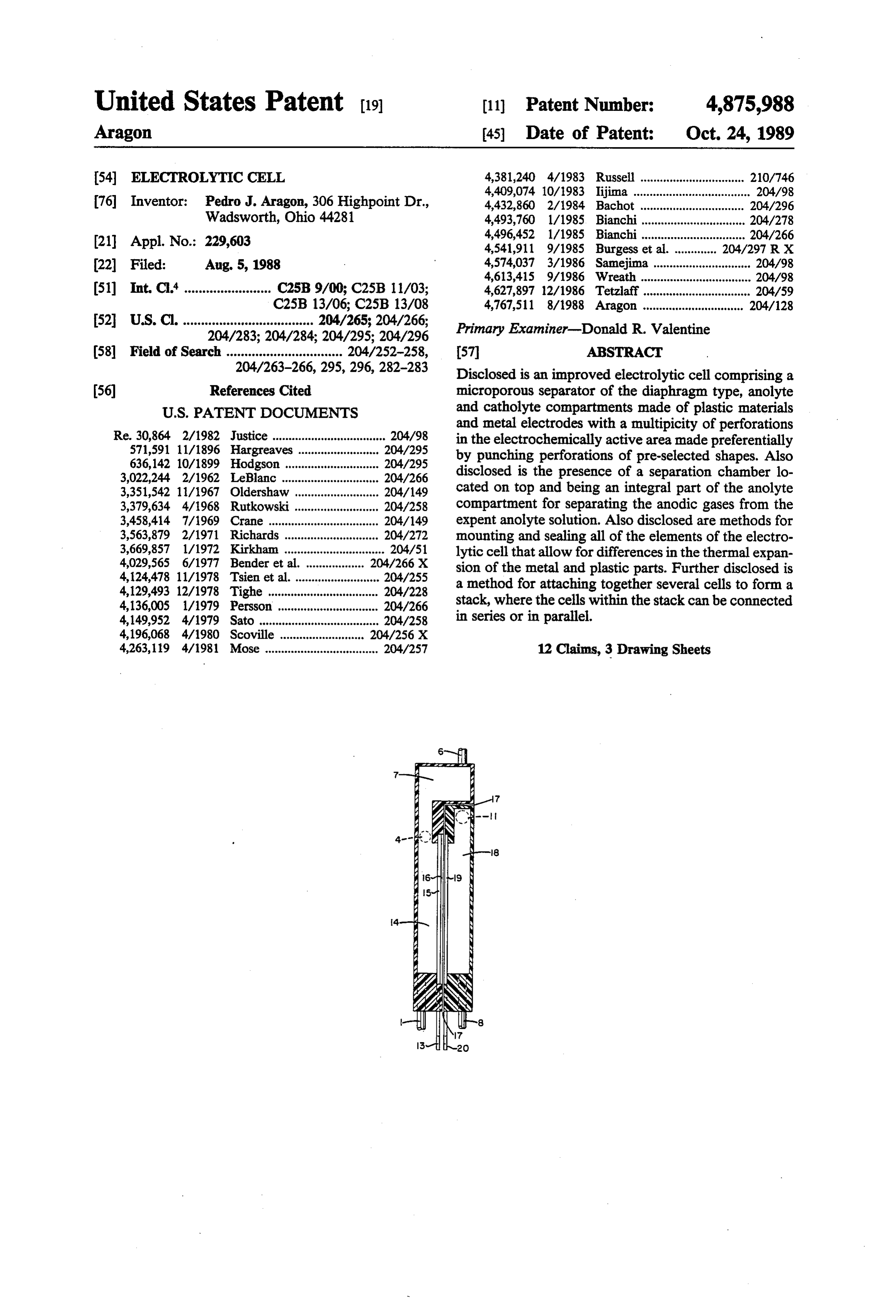
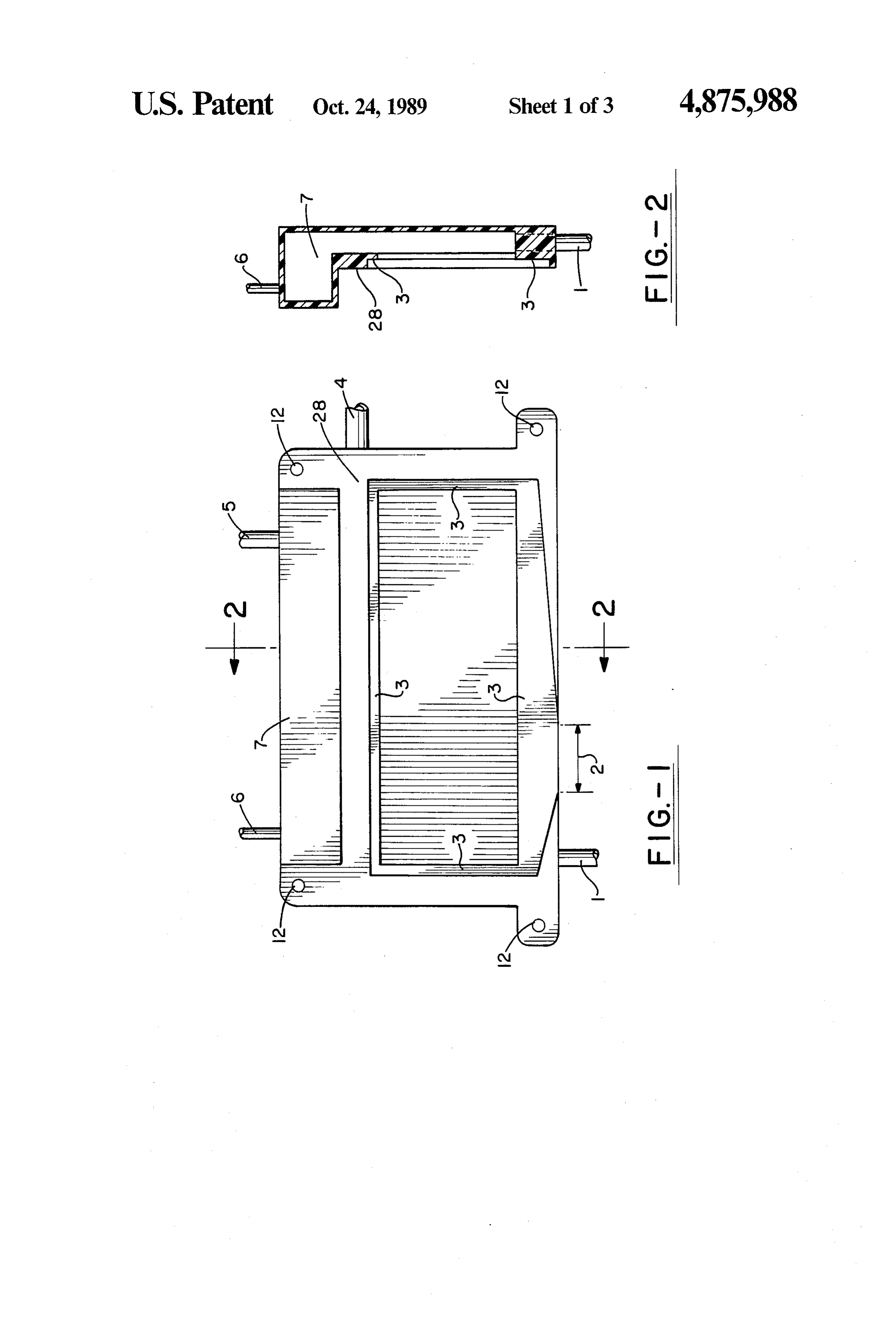
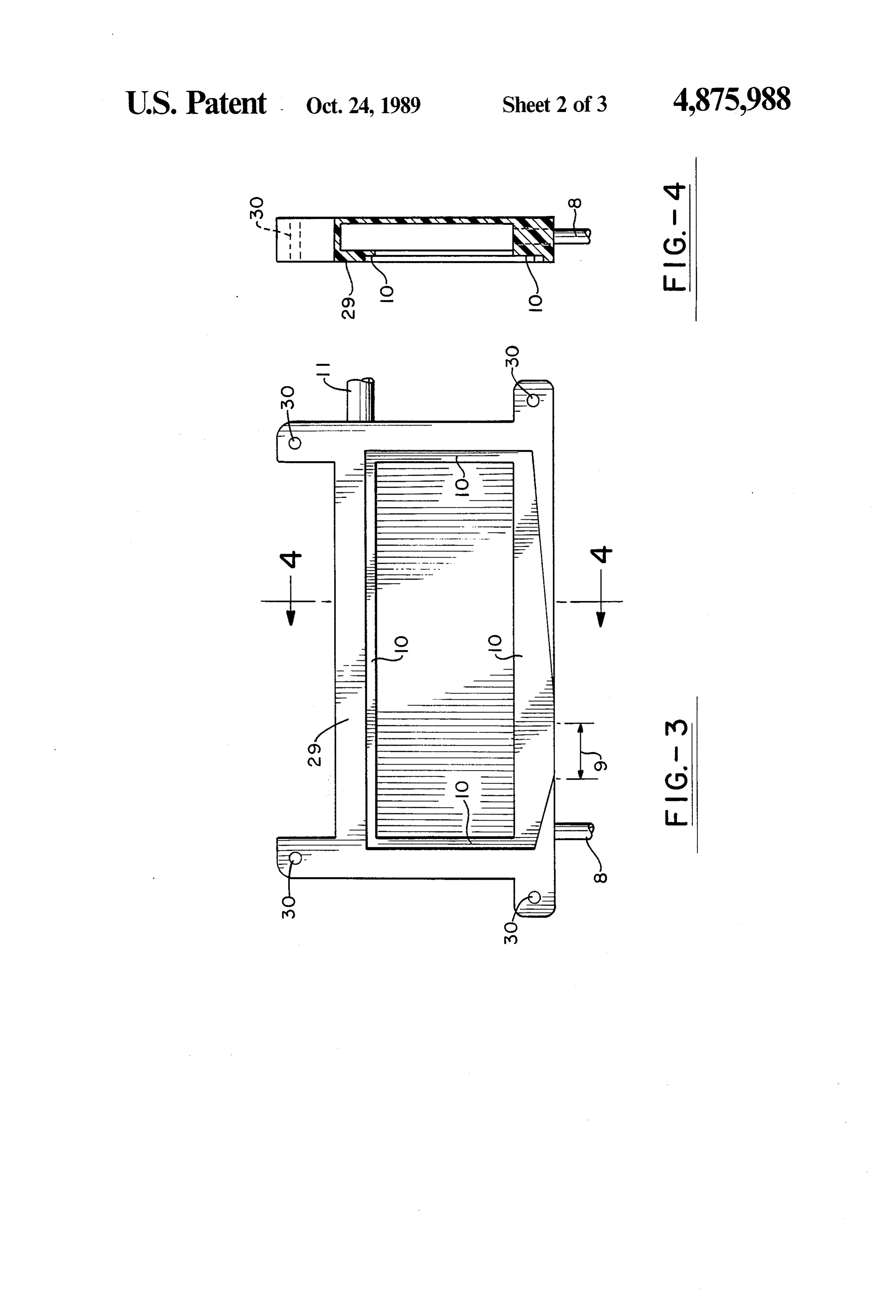
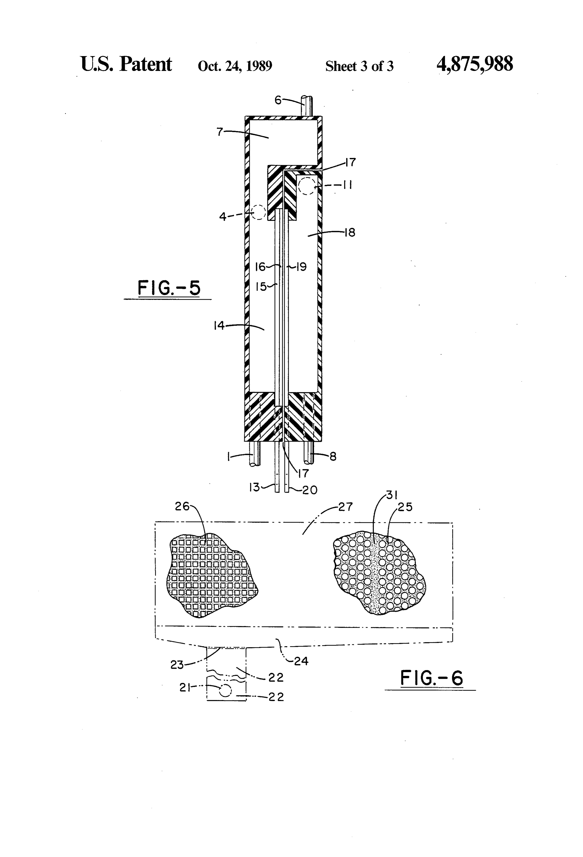
Many attempts have been made in the industry to DESCRIPTION OF THE DRAWINGS develop plastic-bodied cells. Most of these attempts 30 For a complete understanding of the objects, tech have not been successful for several reasons: (a) the niques, and structure of the invention, reference should materials used were not resistant to the environment be made to the following detailed description and ac under the operating conditions, (b) in order to achieve companying drawings wherein:
significant production/day/unit, some designs failed FIG. 1 is a plan view of the anolyte compartment, because the mechanical demands on strength and rigid with the front surface to the viewer; ity could not be met by plastics, (c) some other failed FIG. 2 is a cross section of the anolyte compartment because the material selected could not be machined through the line 2-2 in FIG. 1, showing the gas separa and/or formed according to complicated forms re tion chamber at the top of the anolyte compartment; quired, (d) because of the differences in the expansion FIG. 3 is a plan view of the catholyte compartment, coefficients, at the operating temperature, between the with the front surface to the viewer; plastic cell body and the metal parts, ie. electrical con FIG. 4 is a cross section of the catholyte compart nections and electrodes, it has been difficult to achieve ment through the line 4-4 in FIG. 3; an effective sealing of the cell and prevent leaks of fluid FIG. 5 is a cross section of the assembled cell with all and/or dangerous gases, and (e) the costs associated 4-4elements, its as it could be seen through a plane 2-2 or in FIGS. 1 and 3, respectively; and with the fabrication of large size plastic structures or 45 FIG. 6 presents the general configuration of the metal cell bodies have been too high. electrodes with the type of perforations recommended, The plastic body: The electrolytic cell object of this the lower portion of the electrodes made of a solid sheet invention is a cell where the anolyte and catholyte con partments are made of plastic materials. For the purpose 50 of the same metal, and the protruding connection tab. of this invention herein after, in the specifications and in BEST MODE FOR CARRYING OUT THE the claims, plastic materials are those kind of materials INVENTION that are electrical insulators, non-metallic substances, With reference now to the drawings, and more par that can be laminated, extruded, kept in a permanent ticularly FIG. 1 a view of the plastic anode compart shape when formed in their plastic state, molded, pol 55 ment of the invention with the front surface 28 facing truded, cut and welded or adhesively joined to form the viewer. At the bottom left of the figure the first more complicated forms. The preferred materials are, conduit 1 for receiving a flow of fresh anolyte solution without being exclusive: Chlorinated polyvinyl chlo into the anolyte compartment is shown. Away from the ride (CPVC), polyvinyl chloride (PVC), polyhalogen first conduit, toward the center of the lower side of the hydrocarbons that can be welded to themselves, poly anolyte compartment, the drawing shows the opening 2 propylene, high density polyethylene, many fiber rein to allow the protruding electrode connection tab to exit forced plastics (FRP's) chemically resistant to the com the compartment. Under the number 12 four perfora bination of operating temperatures and chemical envi tions or holes are seen on extensions or ears of the body ronment, and impervious chemically resistant ceramics. of the compartment located on the four corners of the The plastic body (both, the catholyte and the anolyte 65 anolyte compartment. These perforations have the pur compartments) of the present invention can be made by pose of allowing the passage of four bolts for holding molding, poltruding, or by any other suitable technique together the two compartments and the rest of the cell for forming plastic materials. components.
Page 7
As can be seen in the drawing for the catholyte com ment in order to flush out any remaining noxious gases partment, another set of four perforations are in align that may be present.
ment with the perforations in the anolyte compartment. FIG.2 presents a cross section view of the anolyte These perforations have, on one of the compartments, compartment at the line 2-2 in FIG.1. In this drawing called the first compartment, an enlargement located on the separation chamber 7 is seen projecting away from the back surface of the compartment to allow for the the the front surface 28 of the anolyte compartment. The heads of the bolts to be flush with the back surface of indentation 3 is for holding the anode electrode plus a the first compartment when the bolts are tightened. On fraction of the thickness of the separator. Also shown the other compartment, called the second compart are the first conduit 1 and the outlet 5 for the anodic ment, the perforations are threaded so the bolts can be 10 gases produced during the electrolysis plus any other screwed directly into these perforations. It is irrelevant gas that may have been admitted into the separation which compartment holds the head or the end of the chamber through the receiving inlet 6. It is important to bolt. This bolting system allows the stacking together of mention here that the indentation, either in the anolyte several cells without the problem of any protruding part 15 or catholyte compartment could be made deep enough of the bolts to interfere. as to accommodate the metal electrodes plus the whole The drawing also shows the indentation 3 made in the thickness of the separator.
front surface of the anolyte compartment to allow for with FIG. 3 illustrates the plastic catholyte compartment the mounting of the anode electrode plus a fraction of duit the front surface 29 to the viewer. The third con the thickness of the separator. The opening 2, located in locatedforat receiving 8 a flow of fresh catholyte solution is the bottom and next to the side of the catho the lower side of the anolyte compartment, is for allow lyte compartment in such a way that when the electro ing the electrode connection tab to exit the compart lytic cell is assembled, the third conduit will be located ment. This opening is part of the indentation 3.
On the right side of the drawing, and identified by the center and on the bottomthe on the opposite side to first conduit. Towards the of the compartment is located numeral 4, the second conduit is located. This second 25 the opening 9 for the cathode electrode connection tab. conduit is for removing the expent anolyte solution On the opposite side to the third conduit, at the top of from the anolyte compartment. The second conduit, as the catholyte compartment and slightly above the level can be seen in the drawing, is also located immediately of the top of the over the level corresponding to the top side of the 1 for removing cathode the electrode is the fourth conduit catholyte fluid, which is a mixture anode electrode and is positioned on a side opposite that 30 of the cathode reaction products plus the expent catho of the first conduit 1.
The separation chamber 7 is located on the top of the lyte solution. This fourth conduit has a larger diameter anolyte compartment and forms an integral part of it. than the third conduit because it must allow for the easy This separation chamber crosses a separation plane exit of the expent catholyte solution plus the cathodic gases produced on the metal electrode. The indentation between the anode and the cathode compartments to 35 10 for mounting the cathode electrode and part of the occupy. a space available over the catholyte compart separator is shown in this figure, too. Shown in this ment and being flush to a plane of the back surface of the catholyte compartment once the cell is assembled. figure are also the four extensions or ears, with perfora This separation chamber separates the anodic gas pro ment forlocated tions 30 at the corners of the catholyte compart the bolting system.
duced during the electrolysis from the expent anolyte FIG. 4 presents a cross section of the catholyte com solution which flows back under the force of gravity, partment at the line marked 4-4 in FIG. 3. Here, the and exits the anolyte compartment through the second indentation 10, as in the anolyte compartment, is de conduit 4. Also located in the separation chamber is at signed to hold the cathode electrode and part or the least one outlet 5 for removal of the anodic gases pro whole thickness of the separator. The position of the duced during electrolysis and, at least one inlet 6, for 45 third conduit 8 is shown at the bottom of the figure with receiving gases originated from outside of the electro broken lines. The extension at the top of the catholyte lytic cell. This inlet 6 has three functions. For systems compartment, and the perforations 30 for the bolting where the expent anolyte solution is stored in a tank; system are shown also with broken lines. some of the dissolved gases are accumulated in the FIG. 5 illustrates a cross section of the plastic electro space existing above the surface of the liquid. Many 50 lytic cell with all its elements in position. At the bottom times these accumulated gases are toxic and when the of the figure are the anode connection tab 13, the first tank is opened for service, the presence of these gases conduit 1, the cathode electrode connection tab 20 and could become threatening to the health of the operators. the third conduit 8. On the left side of this figure are By connecting this space through the inlet 6 to the shown the space between the anolyte and the catholyte separation chamber 7 of the electrolytic cell, these gases 55 compartment 17 with an elastomer adhesive or "in will be swept through the cell and out of the system. place gasket' substance used for sealing the cell during This operation not only removes or reduces a potential assembly, the space for the anolyte solution 14, the danger, but also helps recuperate valuable gases that anode electrode 15, the separator 16, and the position otherwise could be lost. Further, when the removal of that the second conduit 4 should occupy. At the top of the anodic gases is performed under vacuum, allowing a 60 the figure is shown the inlet 6. On the right of the FIG. certain amount of gas from outside the cell to enter the 5 is shown the separation chamber 7, another portion of separation chamber helps equalize the pressure in both the space between the anolyte and catholyte compart the anolyte and the catholyte compartments. This pres ment where the sealing compound is applied 17, the sure equalization reduces the possibility of producing a position of the third conduit 11, the space for the catho flow of catholyte solution through the separator to the lyte solution 18, and the cathode electrode 19. anolyte compartment. Finally, when the electrolytic The metal electrodes shown in FIG. 6 are generally cell must be disassembled, prior to its opening a certain made of an electrically conductive sheet of metal which amount of air can be allowed to pass into the compart is suitable for the particular electrochemical reaction to
Page 8
take place in the electrolytic cell. The electrodes may One of the main disadvantages of perforated elec have an active coating or catalyst applied on their sur trodes is that, for a certain given geometrical surface, faces for facilitating the electrochemical reaction. FIG. the real active surface of the metal electrode left is, 6 shows the general configuration for the metal elec because of these perforations, just a fraction of the origi trodes used in the electrolytic cell of this invention. The nal geometrical surface. To compensate for this loss, the active area of the electrode 27 is generally perforated real operating current density must be increased, with a for allowing the gases produced on the frontal, and consequent increase in the operating voltage and energy opposing, surfaces of both electrodes to flow to the consumption. Another important consideration is the space located between the back of the electrodes and increase in electrical resistance inside the metal elec the internal walls of the catholyte and anolyte compart 10 trode because of the tortuous path for the electricity ments identified as i8 and 14 respectively, and called created by either expanding or by using wire mesh type the anolyte and the catholyte space. Two preferred electrodes.
possibilities of the type of perforations are shown in The present invention offers solutions to the prob FIG. 6 one is the square perforations 26, where the lems mentioned above.
length of the sides of the perforations are from 0.1 15 Consider first the size and configuration of the perfo inches to four times the thickness of the metal elec rations, when a round hole is punched in a metal sheet, trodes. The recommended width of the metal between square perforations is between one to two times the is small a area of the surface disappears, while a new one thickness of the metal electrode. These square perfora eliminated on created
the walls of the perforation. The area a circular perforation can be expressed tions have their sides parallel to the top and sides of the 20 by:
active area of the electrode. The reason for this align ment is to reduce the resistance to the flow of electricity A=Tr"(diameter)A2 (1) from the connecting tab up to all of the active area by providing straight lines of conducting metal from the While the area of the newly created surface is given by: bottom to the top of the electrode. 25
Another possible configuration for the perforations is B=rdiameter'thickness (2) in the form of circular holes 25. The preferred perfora tion pattern is a closed package or triangular pitch. However, not all of the newly created surface becomes These circular perforations have diameters from 0.1 an efficient current conductor (or active surface). Previ inches to four times the thickness of the metal electrode. 30 ous experiments reported in the literature have shown When the circular perforations are used, it is important that the region carrying any significant current can be to include regions of solid electrode material thereon reduced up to a small fraction of the thickness of the called conductive bands, shown as 31 in FIG. 6, to metal, or the length of the perforation. Therefore, equa facilitate and equally distribute the flow of current from tion (2) must be modified to reflect this fact: the bottom to all of the electrode active surface. The 35 width and distance between these solid regions may B(effective)=b'T'diameter' thickness, (3) change according to the overall dimensions of the elec trodes, but the preferred width of the conductions where b is the fraction of the thickness of the metal bands is between two to three times the thickness of the electrode contributing with any significance to the elec metal electrode. The distance between conduction trochemical reaction.
bands should be no greater than three inches. Welded at By equating (1) and (2) we obtain:
23 to the lower solid portion of the electrodes 24 is a **(diameter)A2=b'T'diameter"thickness, (4) connecting tab. 22 with a perforation 21 for connecting the electrode to the electrical power line.
These electrodes can be produced in an automated 45 or that:
production line by: (a) punching the holes, according to effective diameter=4thickness"b (5) any pre-design pattern, (b), cutting-off the shape of the electrode, including the solid portion at the bottom, (c) cutting the connecting tabs, and (d) welding the con Another rations factor to consider is that the size of the perfo must be such that they will allow the easy pas necting tab, at 23, to the rest of the electrode as shown sage of the bubbles 50 to the space behind the electrode.
in FIG. 6.
The protruding tab is preferentially located as shown for the gas bubbles to pass the
For all practical purposes, minimum diameter size in FIG. 6, but could also be located at the ends and in fore, the effective diameter (D) of the0.1circular is about inches. There perfora alignment with the side of the electrodes. Other config tions must be between 0.1 inches and four times the urations are not excluded. 55 thickness of the metal electrode. Thus, if the metal elec The main reason for the existence of perforated elec trode is 0.040 inches thick, the diameter of the perfora trodes is the desire to provide the interelectrode gap tion should be between 0.1 to 0.16 inches. The recom with a way for the gases to exit this gap and thus reduce mended distance between holes is, at least, equal to the the electrical resistance in this interelectrode space. thickness of the metal, ie. in this case, it will be equal to There have been many arguments in the past about the 0.040 in. or larger.
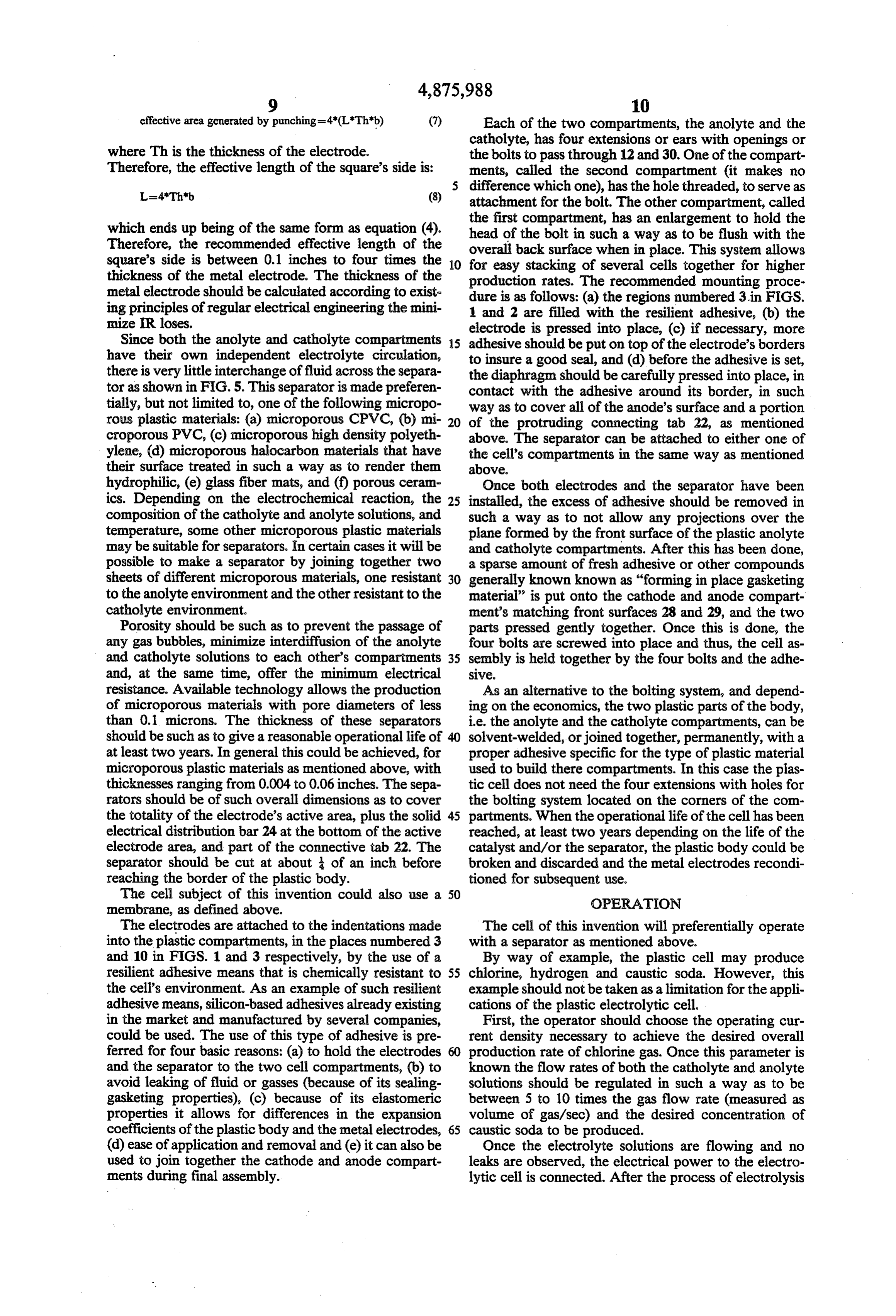
shape and form of these perforations. Some designs call An alternative to the punched circular perforation is for expanded metal, some use wire mesh configurations, square-shaped perforations, with the the sides of the some call for solid sheets of metal with no perforations squares aligned parallel with the top border of the ac at all and some use perforated holes of different diame tive area. In this case, similar considerations as men ters. It is believed that there has not been any rational 65 tioned for the circular perforations can be made here: criteria for selecting the diameter and configuration of the holes, except for empirical correlations made from area of a square of side L=LL (6) the experience of each designer.
Page 9
effective area generated by punching=4*(L"Th"b) (7) Each of the two compartments, the anolyte and the where This the thickness of the electrode.
catholyte, has four extensions or ears with openings or the bolts to pass through 12 and 30. One of the compart
Therefore, the effective length of the square's side is: ments, called the second compartment (it makes no
difference which one), has the hole threaded, to serve as attachment for the bolt. The other compartment, called the first compartment, has an enlargement to hold the which ends up being of the same form as equation (4). head of the bolt in such a way as to be flush with the Therefore, the recommended effective length of the overal back surface when in place. This system allows square's side is between 0.1 inches to four times the 10 for easy stacking of several cells together for higher thickness of the metal electrode. The thickness of the production rates. The recommended mounting proce metal electrode should be calculated according to exist dure is as follows: (a) the regions numbered 3 in FIGS. ing principles of regular electrical engineering the mini and 2 are filled with the resilient adhesive, (b) the mize IR loses. electrode is pressed into place, (c) if necessary, more Since both the anolyte and catholyte compartments 5 adhesive should be put on top of the electrode's borders have their own independent electrolyte circulation, to insure a good seal, and (d) before the adhesive is set, there is very little interchange of fluid across the separa the diaphragm should be carefully pressed into place, in tor as shown in FIG. 5. This separator is made preferen contact with the adhesive around its border, in such tially, but not limited to, one of the following micropo way as to cover all of the anode's surface and a portion rous plastic materials: (a) microporous CPVC, (b) mi 20 of the protruding connecting tab 22, as mentioned croporous PVC, (c) microporous high density polyeth above. The separator can be attached to either one of ylene, (d) microporous halocarbon materials that have the cell's compartments in the same way as mentioned their surface treated in such a way as to render them above.
hydrophilic, (e) glass fiber mats, and (f) porous ceram Once both electrodes and the separator have been ics. Depending on the electrochemical reaction, the 25 installed, the excess of adhesive should be removed in composition of the catholyte and anolyte solutions, and such a way as to not allow any projections over the temperature, some other microporous plastic materials plane formed by the front surface of the plastic anolyte may be suitable for separators. In certain cases it will be and catholyte compartments. After this has been done, possible to make a separator by joining together two a sparse amount of fresh adhesive or other compounds sheets of different microporous materials, one resistant 30 generally known known as "forming in place gasketing to the anolyte environment and the other resistant to the material” is put onto the cathode and anode compart catholyte environment. ment's matching front surfaces 28 and 29, and the two Porosity should be such as to prevent the passage of parts pressed gently together. Once this is done, the any gas bubbles, minimize interdiffusion of the anolyte four bolts are screwed into place and thus, the cell as and catholyte solutions to each other's compartments 35 sembly is held together by the four bolts and the adhe and, at the same time, offer the minimum electrical SWe resistance. Available technology allows the production As an alternative to the bolting system, and depend of microporous materials with pore diameters of less ing on the economics, the two plastic parts of the body, than 0.1 microns. The thickness of these separators i.e. the anolyte and the catholyte compartments, can be should be such as to give areasonable operational life of 40 solvent-welded, or joined together, permanently, with a at least two years. In general this could be achieved, for proper adhesive specific for the type of plastic material microporous plastic materials as mentioned above, with used to build there compartments. In this case the plas thicknesses ranging from 0.004 to 0.06 inches. The sepa tic cell does not need the four extensions with holes for rators should be of such overall dimensions as to cover the bolting system located on the corners of the con the totality of the electrode's active area, plus the solid 45 partments. When the operational life of the cell has been electrical distribution bar 24 at the bottom of the active reached, at least two years depending on the life of the electrode area, and part of the connective tab. 22. The catalyst and/or the separator, the plastic body could be separator should be cut at about of an inch before broken and discarded and the metal electrodes recondi reaching the border of the plastic body. tioned for subsequent use.
The cell subject of this invention could also use a 50 OPERATION membrane, as defined above.
The electrodes are attached to the indentations made The cell of this invention will preferentially operate into the plastic compartments, in the places numbered 3 with a separator as mentioned above. and 10 in FIGS. 1 and 3 respectively, by the use of a By way of example, the plastic cell may produce resilient adhesive means that is chemically resistant to 55 chlorine, hydrogen and caustic soda. However, this the cell's environment. As an example of such resilient example should not be taken as a limitation for the appli adhesive means, silicon-based adhesives already existing cations of the plastic electrolytic cell. in the market and manufactured by several companies, First, the operator should choose the operating cur could be used. The use of this type of adhesive is pre rent density necessary to achieve the desired overall ferred for four basic reasons: (a) to hold the electrodes production rate of chlorine gas. Once this parameter is and the separator to the two cell compartments, (b) to known the flow rates of both the catholyte and anolyte avoid leaking of fluid or gasses (because of its sealing solutions should be regulated in such a way as to be gasketing properties), (c) because of its elastomeric between 5 to 10 times the gas flow rate (measured as properties it allows for differences in the expansion volume of gas/sec) and the desired concentration of coefficients of the plastic body and the metal electrodes, 65 caustic soda to be produced. (d) ease of application and removal and (e) it can also be Once the electrolyte solutions are flowing and no used to join together the cathode and anode compart leaks are observed, the electrical power to the electro ments during final assembly. lytic cell is connected. After the process of electrolysis
Page 10
starts, the installation should be checked for leaks. I claim:
These checks should be repeated periodically. Because 1. An improved electrolytic cell of the type having a each of the compartments has an independent flow of catholyte compartment, an anolyte compartment, a flat electrolyte and discharge of gases, very little mixing of cathode electrode, a flat anode electrode, and a separa catholyte and anolyte solutions should occur. To verify 5 tor located between the anode and the cathode elec that the separator is working properly, the expent brine trodes, wherein the improvement comprises: and the caustic produced should be periodically (a) a separation chamber located at the top and being checked for hypochlorites and salt impurities respec an integral part of said anolyte compartment cross tively. This provision will result in the following advan ing a separator plane between said anode and cath tages. A negligible amount of salt will diffuse to the 10 ode compartments to occupy a space available catholyte compartment. This situation will result in big over said catholyte compartment and being flush to savings in the evaporation-separation stage, if this stage a plane of a back surface of said catholyte compart is part of the overall process. In any case, the caustic ment to separate gas produced during the electrol produced will have very little amount of salt in it, and ysis from expent anolyte solution, and having at could be used directly in some of those applications 5 least one outlet for removal of anodic gases pro where caustic with low salt concentration is required. duced during electrolysis, and at least one inlet for Since, practically, there is no fluid flow between the receiving gases originated from outside of said two compartments, no significant amount of chlorine electrolytic cell.
will pass to the cathode compartment and therefore, no formation of highly corrosive species like hypochlorites 20 2. The improvements in an electrolytic cell as recited and/or chlorates will be formed. In those cases where in claim 1, further comprising:
the chlorine, or any other anodic gases, is aspirated a first conduit for receiving a flow of fresh anolyte from the separation chamber and injected into a water solution into said anolyte compartment located at the bottom and next to one of the lateral sides of stream and the expent brine returned to a resaturation said anolyte compartment, and a second conduit tank, it may be very useful to connect the top (liquid 25 for removing expent anolyte solution from said free) part of the tank to the inlet on top of the separation anolyte compartment located on a lateral side to chamber. This operation will remove the chlorine said anolyte compartment and on the opposite side fumes from the resaturation tank and thus reduce the problems that originate during the replacement of salt in to said first conduit and at a level immediately the tank. If this method is not used a certain amount of 30 above and parallel to a level corresponding to the chlorine gas could be released to the environment. top side of the anode electrode. Presently, most of the electrolytic cells available for 3. The improvements in an electrolytic cell as recited industrial production of chlorine and caustic soda are in claim 1, further comprising:
designed and constructed with either a "monopolar' or a third conduit for receiving a flow of fresh catholyte "bipolar' configuration. These configurations do not 35 feeding solution into said catholyte compartment render much flexibility in the way cells are "stacked” located in the bottom and next to the side of said together to form large production units. Some of these catholyte compartment and in opposition to said problems are discussed by Mose et al in U.S. Pat. No. first conduit located in the anolyte compartment, 4,263,119. Because each of the cells of this invention are and a fourth conduit for removing the fluid product fully operational by themselves and their compartments of the cathode electrode reaction located on a lat are electrically non-conductive, they can be stacked in eral side of said catholyte compartment and on an in parallel or in series. What is also very important is the opposite side the said third conduit and at a level fact that this configuration can be changed in the future immediately above and parallel to a level corre without need to make changes in the cell stack or its sponding to the top side of the cathode electrode. support structure. 45 4. The improvement in an electrolytic cell as recited Because each cell is fully operational by itself and in claim 1, wherein said separator is an asbestos-based their compartments are made of impervious, electrically material.
non conductive plastic, the stack of cells can be put 5. The improvement in an electrolytic cell as recited together without the need of high compression devices. in claim 1, wherein said separator is made of micropo This feature also allows for the easy replacement of any 50 rous plastic materials.
cell in the stack without having to shut down the other 6. The improvement in an electrolytic cell as recited cells in the stack and therefore reduces possible produc in claim 5, wherein the separator is made by joining tion losses and maintenance costs. together two layers of different microporous materials Because each cell is fully operational by itself, the 7. The improvements in an electrolytic cell as recited stack of cells and the cells in a stack could be connected 55 in claim 1, wherein:
in such a way as to adapt to the electrical power source said anode electrode and cathode electrode have in available. This characteristic becomes very important their active surface a multiplicity of perforations if, for any reason, the power source must be replaced in for allowing gases produced on frontal surfaces of the future. the electrodes to flow to the space located between Thus it can be seen that the objects of the invention the back of said electrodes and internal walls of the have been satisfied by the structure presented herein anolyte and catholyte compartments, and where a above. While in accordance with the Patent Statutes lower portion of said electrode is a solid sheet of only the best modes and preferred embodiments of the the same metal to which a protruding connection invention have been presented and described in detail, tab is welded.
the invention is not limited thereto or thereby. Accord 65 8. The improvement in an electrolytic cell as recited ingly, for an appreciation of the true scope and breath of in claim 7 where the perforations made in the metal the invention, reference should be made to the ap electrodes are circular with a diameter size from 0.07 pended claims. inches to four times the thickness of the metal electrode.
Page 11
9. the improvement in an electrolytic cell as recited in where the length of the perforation's sides are from 0.07 claim 7, where said circular perforations are spaced by inches to four times as long as the thickness of said conduction bands between 0.08 to 0.24 inches wide, electrode, and where the sides are aligned parallel to the located parallel to the sides of an active area and extend top and lateral sides of the active area of the electrode. ing from a lower solid sheet portion to the top of the 5 electrode active area, and with a separation between in 11. The improvement in an electrolytic cell as recited claim 7, where said anode electrode has perforations conduction bands from 2 to 4 inches.
10. The improvement in an electrolytic cell as recited of different shape from those of said cathode electrode. in claim 7, where said electrodes have square perfora 2. The improvement in an electrolytic cell as recited tions for allowing gases produced on the frontal sur O in claim 7, where a lower portion of the electrodes is a faces of the electrodes to flow to the space located solid sheet of the same metal to which a protruding between the back of the electrodes and the internal connection tab is welded.
walls of said anolyte and catholyte compartments, and as
Provenance
- Collection
- Cited prior art
- Original PDF
- patentimages.storage.googleapis.com →
- Filed
- 1988-08-05
- Pages
- 11
- Method
- pdftotext (the PDF's own text layer) + pdftoppm 300dpi page scans
- Source
- Google Patents bibliographic record
- Granted
- 1989-10-24
- Inventors
- Pedro J. Aragon
- Transcribed from
- patentimages.storage.googleapis.com →