patent · US3759813
Electrolytic cell
18 September 1973
Page 1
Sept. 18, 1973 C. W. RAETZSCH ET All 3,759,813
ELECTROLYTIC CELL
Filed July l, 197l 5 Sheets-Sheet LLLLLL LLLLLL LL LLL LLL LLL LLL LLLLLLLL LL LLLLLLLLS s
awayaravanawamaan
AAAA Nils waun
Page 2
Drawing sheet — no readable text.
Page 3
Drawing sheet — no readable text.
Page 4
Drawing sheet — no readable text.
Page 5
Sept. 18, 1973 C. W. RAETZSCH ET All- 3,759,813
ELECTROLYTIC CELL
Filed July 1, 197l 5 Sheets-Sheet &
LLLLLL LLLLHHLHHLH LLHHLALSHAHHLAAL HuuHAHL AAA
AZZAZZZ WAZI US ZZZZZ77Z77, 7. SLSLSSLSLSSLSLLSSLSLSLSSLSLSSLLSLSLLSLSSSLLLSLLLSLSLLLSLSL LSLSLLLLLSLLLLLSLLLL LL
INVENTORs
ATTORNEYs
Page 6
United States Patent Office Patented Sept. 18, 1973
SUMMARY OF INVENTION
3,759,813 In order to take advantage of the apparent economies
ELECTROLYTC CELL
Carl W. Raetzsch, William B. Darlington, and Hugh of bipolar electrolyzers, electrolysis should be conducted Cunningham, Corpus Christi, Tex., assignors to PPG at high anode current densities and brine feed rates. Industries, Inc., Pittsburgh, Pa. When electrolysis is carried out at high anode current Continuation-in-part of application Ser. No. 55,680, densities, for example, above about 100 amperes per July 17, 1970, now abandoned. This application square foot, it is important that the electrical current July 1, 1971, Ser. No. 158,695 flow efficiently through the backplate. This becomes more Int. CI. B01k 3/06; C01b 11/26 important when the backplate is a sandwich of two metals, U.S. C. 204-256 14 Clains O as titanium and steel. - One way of insuring that the flow of electricity through
ABSTRACT OF THE DISCLOSURE the backplate is efficient (i.e., that the voltage drop across A novel bipolar unit for use in bipolar diaphragm cell the backplate is low or negligible) is to provide within electrolyzers is disclosed. Both members of the backplate the sandwich of titanium and steel of the backplate tight, 5 metal-to-metal contact between the titanium and the of the bipolar unit-the anodic surface and the cathodic steel, for example as at an interface. Another may is to surface-are metallic. The backplate is particularly resist rely upon other electrically conductive structures in the ant to hydrogen-induced structural failure. backplate to carry the current from the cathodes or cathodic plate, through the backplate, to the anodes con
CROSS-REFERENCE TO RELATED APPLICATION 20 nected thereto, e.g., to provide copper studs which ex tend through the backplate for conducting current.
This is a continuation-in-part of our copending U.S. It has been discovered in operating bipolar electro application Ser. No. 55,680, filed July 17, 1970, now lyzers with backplates having steel and titanium members, abandoned. such as described above, that atomic hydrogen generated BACKGROUND OF THE INVENTION on the steel cathodic surface of the backplate migrates through the steel toward the titanium member of the
Aqueous solutions of alkali metal halides, as sodium backplate. This hydrogen is generated by the electrical chloride and potassium chloride, are electrolyzed to yield current that passes from the anode through the electrolyte the alkali metal hydroxide, the halogen, and hydrogen. in a straight line path directly to the steel cathodic sur This electrolysis is generally carried out in one of two face of the backplate, thereby causing electrolysis on the types of cells, the mercury cell and the diaphragm cell. steel cathodic surface.
In the diaphragm cell there are two electrolyte com In electrolytic cells having a titanium-steel bond, the partments. One is the cathode electrolyte compartment or passage of the hydrogen so generated, through the steel catholyte compartment. The other compartment is the member toward the titanium member, is deleterious to anode electrolyte compartment or anolyte compartment. 35 the structural integrity of the backplate. In due course this These two compartments are separated by a semi-per migration of hydrogen atoms is apt seriously to weaken meable diaphragm, typically of asbestos. Diaphragm cells the strength of the steel-titanium backplate, and can be may be electrically connected in series in a common hous expected to weaken the steel-titanium bond, possibly lead ing, with the anodes of one diaphragm cell being in series 40 ing to the flaking off of the titanium and the misalign electrically with the cathodes of the prior cell in the cir ment of the anodes. Additionally, when the steel cathodic cuit and mounted on the opposite side of a common struc member of the backplate has been fabricated from steel tural member (e.g., a backplate) therewith, and the cath that has been subjected to considerable amount of cold odes of the cell being in series with the anodes of the next working, the hydrogen may cause blistering of the steel. adjacent cell in the circuit, and mounted on common In electrolytic cells having current conducting means from structural member. Such a configuration is called a bi the cathodes, through the backplate, to the anodes, the polar configuration. An assembly of diaphragm cells in formation of the hydride may lead to misalignment bipolar configuration, the anodes of one cell being elec of the anodes. In accordance with this invention, migra trically in series with and physically connected to the tion of atomic hydrogen through the steel into contact cathodes of the next adjacent cell by means of a com 50 with the titanium within the backplate is prevented or mon structural member within the electrolyzer, is called substantially minimized. This is accomplished by sup an "electrolyzer.' pressing the formation of atomic hydrogen on the ca The common member, having a backplate with both thodic side of the backplate by reducing the hydrogen the anodes of one cell and the cathodes of the next ad atom migration from the backplate through the steel mem jacent cell in the series connected thereto, is called a 5 5 ber of the backplate to the titanium mimeber and by “bipolar unit.' protecting the titanium member from contact by atomic The assembly provided by the anodes of one bipolar hydrogen.
unit interleaved with the cathodes of the adjacent bi Any of a variety of specific expedients may serve to ac polar unit and facing each other so that electrolysis of complish this. For example, the migration of hydrogen alkali metal chloride solutions surrounding these anodes 60 atoms through the steel member of the backplate may be and cathodes may be carried out therebetween, is called reduced by interposing between the catholyte and the steel a "bipolar cell.” member of the backplate a coating providing a barrier Bipolar electrolyzers are described in Mantell, Electro to the migration of hydrogen atoms so that the atomic chemical Engineering (4th Ed.), McGraw-Hill Book Co., hydrogen is prevented from entering the steel member of Inc., New York, N.Y. (1960), and in Kircher, "Electrol the backplate. In addition to or in lieu of the hydrogen ysis of Brines in Diaphragm Cells” in Sconce, Chlorine, barrier coating, steps may be taken to provide for the Reinhold Publishing Corp., New York, N.Y. (1962). Bi combination of the atomic hydrogen to molecular hydro polar electrolyzers of the prior art are shown in U.S. gen before the atomic hydrogen reaches the titanium Patent 1,907,818 to R. M. Hunter, U.S. Patent 2,161,166 member of the backplate. And further, in addition to or to R. M. Hunter, U.S. Patent 2,282,058 to R. M. Hunter, O in lieu of either of the expedients described above, a
ent 3,337,443 to Raetzsch et al. gen overvoltage higher than the hydrogen overvoltage of
Page 7
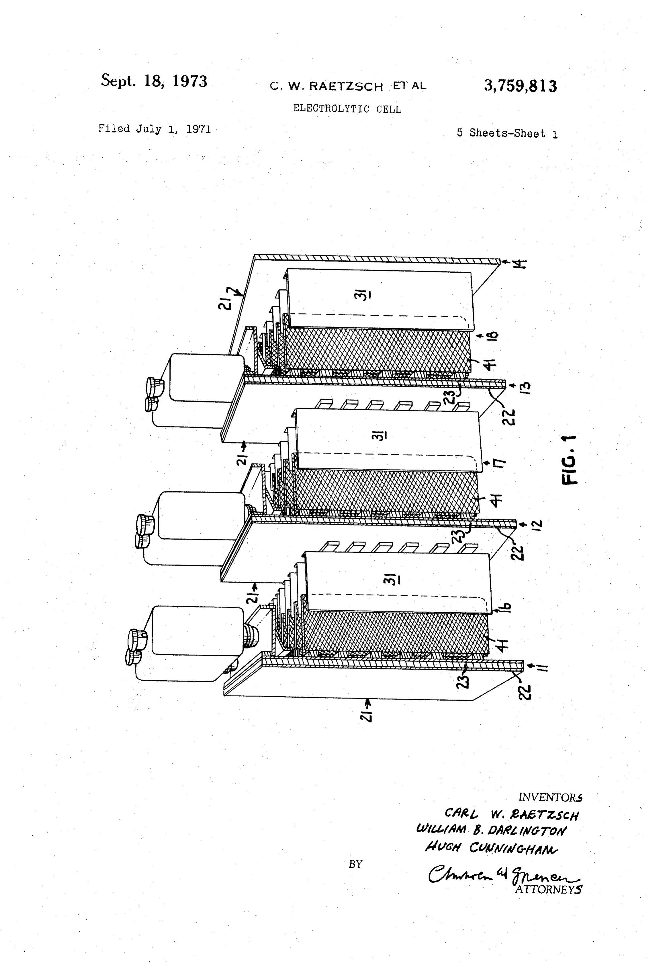
the cathodes so that the generation of atomic hydrogen 31 of the one unit 13 and the cathodes 41 of the next on the backplate is substantially reduced. adjacent unit 12 in the electrolyzer are interleaved within DESCRIPTION OF THE INVENTION cell 17, with the anodes 31 positioned between and paral lel to the cathodes 41. Best results are obtained if the
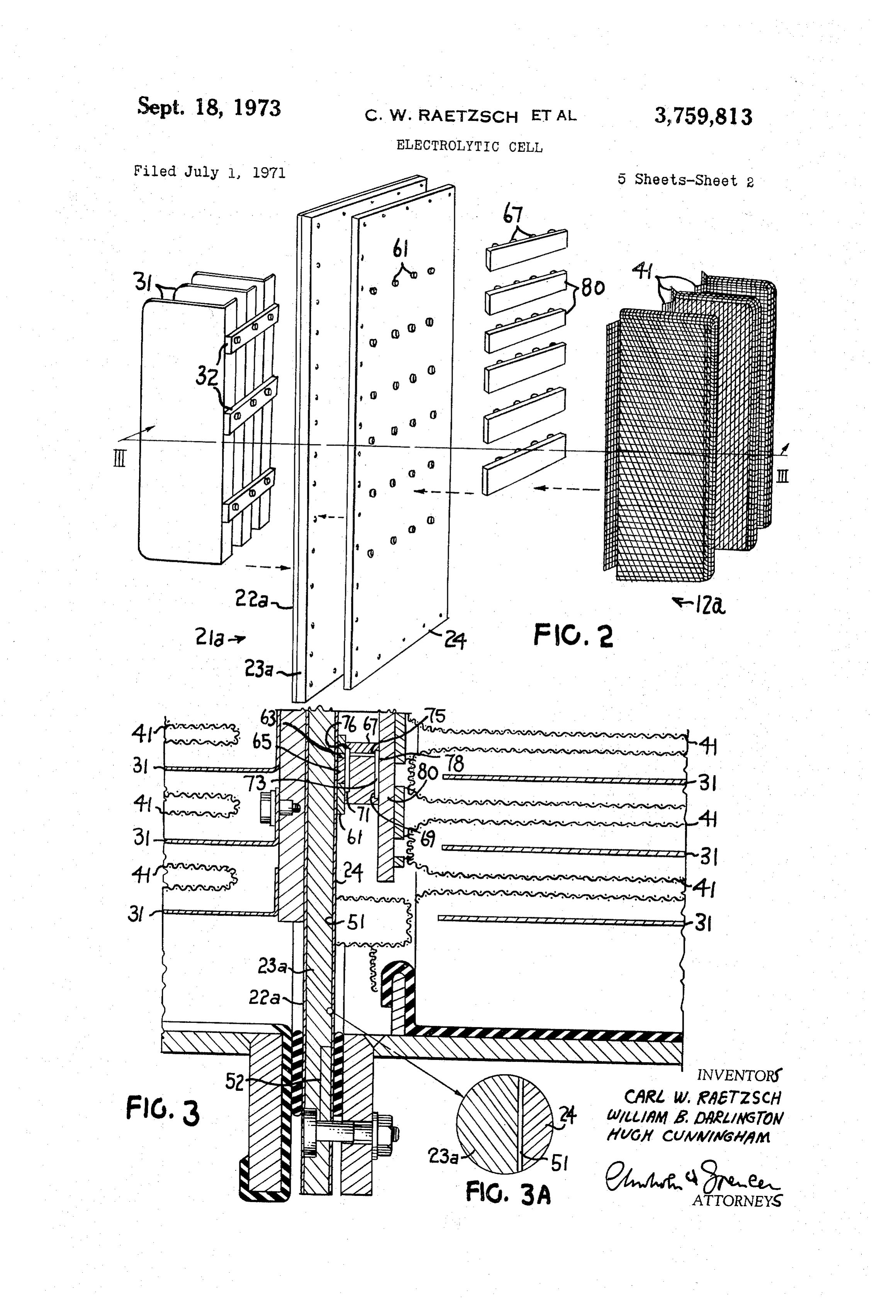
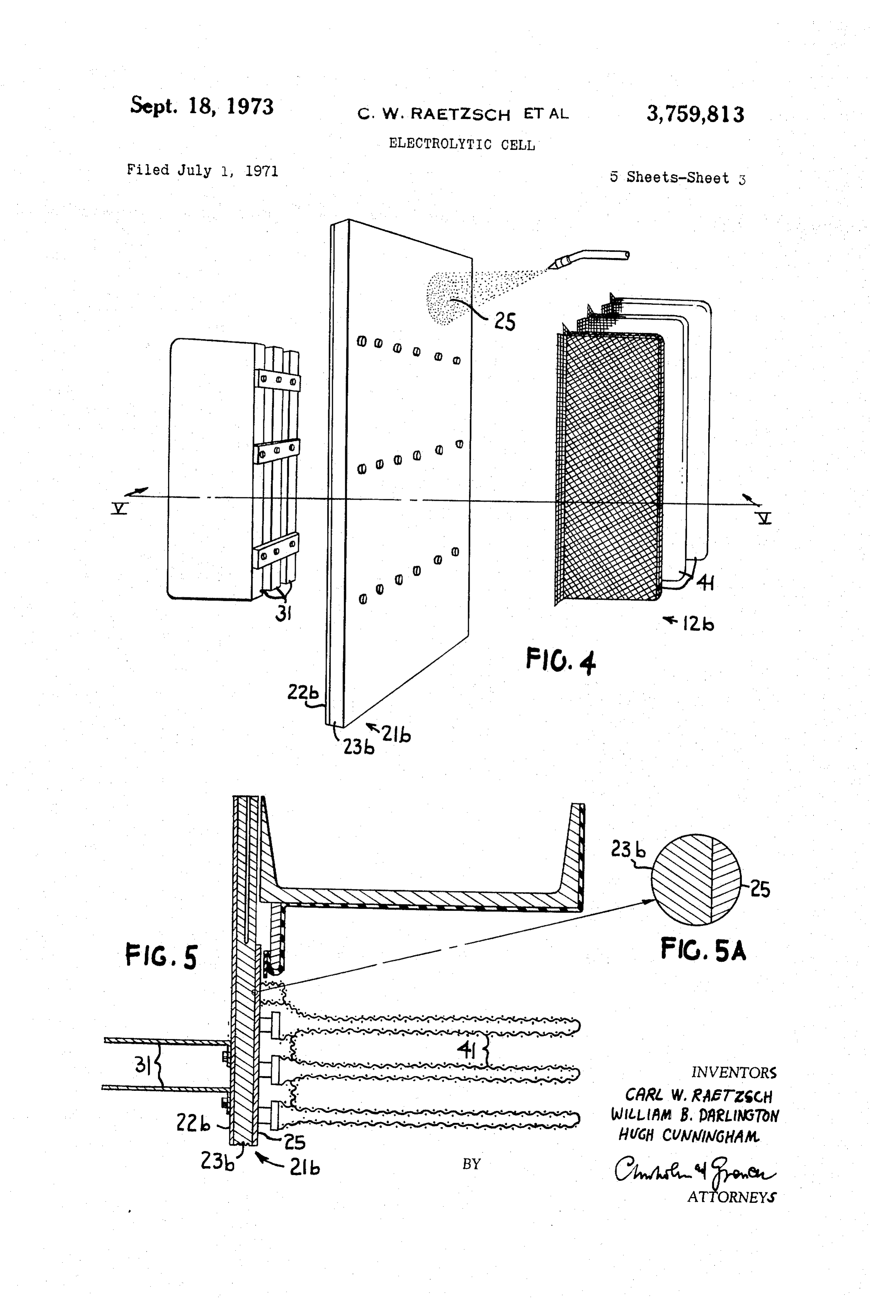
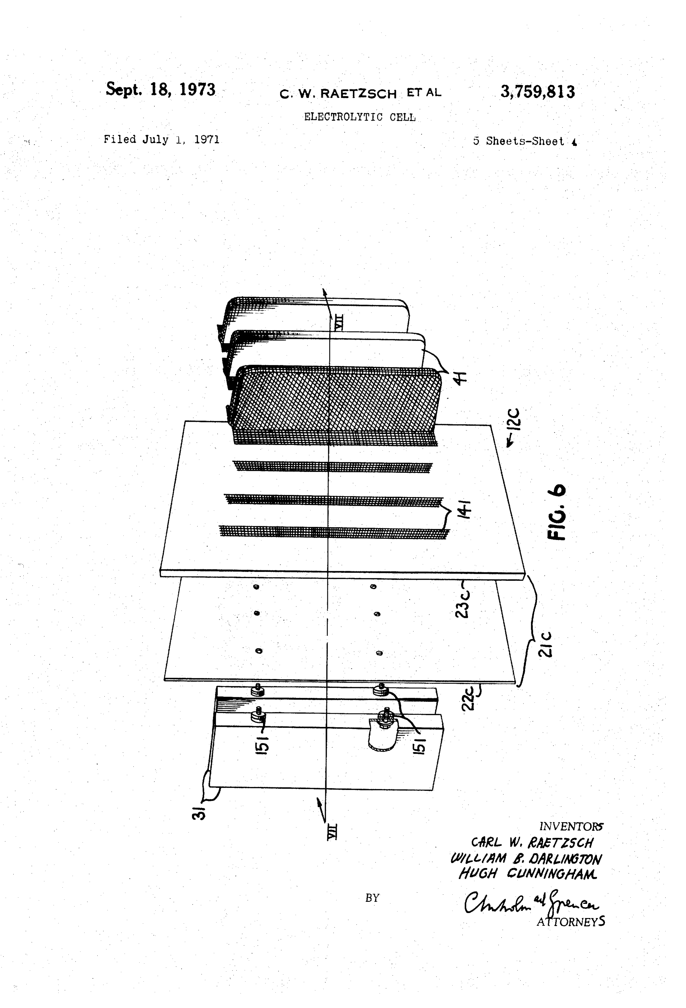
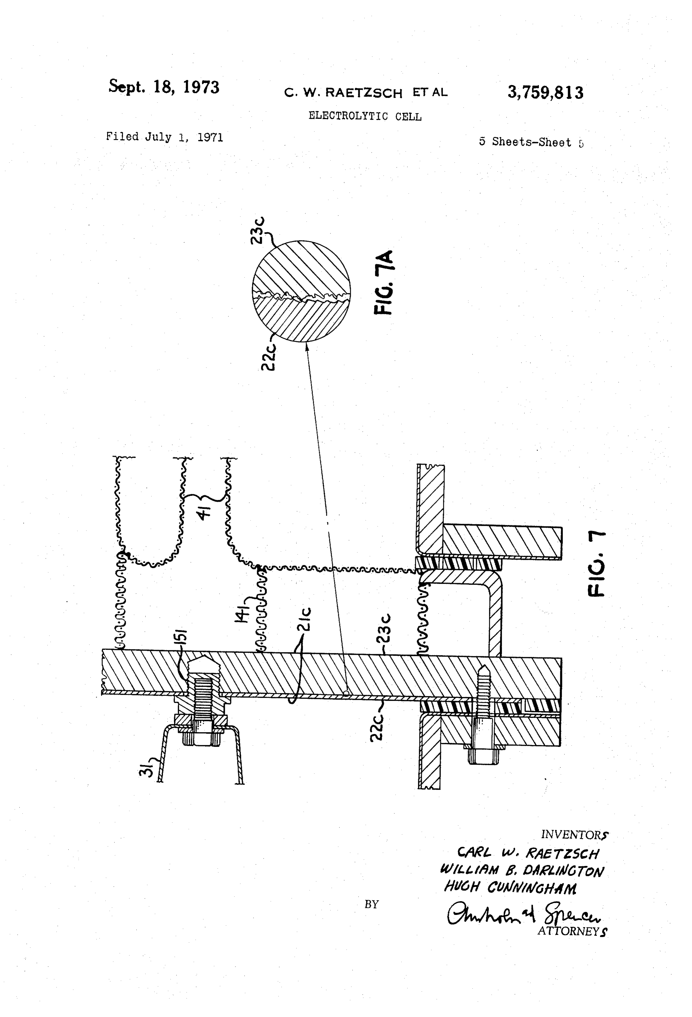
Specific exemplifications of the invention disclosed here 5 anode 31 is equidistant from the two cathodes 41 on either in may be further understood by reference to the figures: side of it.
FIG. 1 is an exploded partial cut-away perspective of In the process of electrolysis, electrical current flows a bipolar electrolyzer. from the backplate 21 of bipolar unit 13 through the FIG. 2 is an exploded perspective view of a bipolar unit anodes 31 attached thereto. Most of the current travels of one embodiment of the invention. O from anode 31 through the electrolyte and diaphragm to FIG. 3 is a cut-away drawing along plane III-III of the cathode 41 attached to the backplate 21 of the next the bipolar unit of FIG. 2. bipolar unit 12 in the electrolyzer. This current flow is FIG. 3A is an enlarged view of a portion of FIG. 3. Substantially perpendicular to the electrodes 31 and 41. FIG. 4 is an exploded perspective view of another em The current then flows through cathode 41 to the back bodiment of this invention. 15 plate 21 of the next unit 12. FIG. 5 is a cut-away drawing along plane V-V of the Some of the current, typically from about 2 percent to bipolar unit of FIG. 4. about 20 percent of the current flowing through the cell, FIG. 5A is an enlarged view of a portion of FIG. 5. however, flows from the anode; more specifically, from FIG. 6 is an exploded perspective view of a bipolar the part of the anode nearest the cathodic surface of the unit of another embodiment of this invention. backplate, through the electrolyte to the backplate. This FIG. 7 is a cut-away drawing along plane VII-VII of Current causes electrolysis at the cathodic face of the the bipolar unit of FIG. 6. backplate and gives rise to an electrolytic current density FIG. 7A is an enlarged portion of FIG. 7. of about 2 to 20 amperes per square foot on the back. An arrangement of bipolar units forming an electrical plate. The hydrogen that is so liberated on the cathodic series of bipolar cells in an electrolyzer is shown in FIG. 25 face of the backplate is believed to be the principal source 1. Bipolar units 11, 12, 13, and 14 form bipolar cells 16, of hydrogen that migrates through the steel member of 17, and 18. End unit 11 provides a cathodic half cell, the backplate toward the titanium member in electrolyzers while end unit 14 provides an anodic half cell. The in of the type shown in FIG. 1.
termediate bipolar units 12 and 13 are bipolar units pro Migration of the atomic hydrogen through the steel viding both anodic and cathodic half cells. 30 member 23 of the backplate 21 to the titanium member 22 In addition to having end half units 11 and 14, an of the backplate 21 results in the formation of titanium electrolyzer will normally include at least one bipolar unit hydride wherever the hydrogen contacts the titanium. This 12 and may be comprised of a plurality (up to 10 or 15, initially occurs on the Surface of the titanium member 22 or even more) of bipolar units 12 and 13. Thus, while facing the steel member 23. The formation of the titani only two intermediate units are shown in FIG. 1, bipolar 35 um hydride on the titanium member causes misalignment diaphragm electrolyzers with any number of bipolar units of the anodes. In those electrolyzers wherein the titanium are included within the contemplation of this invention, member of the backplate is bonded to the steel member the number of such units being limited only by economic thereof, such hydride formation may cause the flaking considerations. off of the titanium member 22 of the backplate 21 and An individual bipolar unit 12 in an electrolyzer com 40 may eventually cause the anodes 31 to fall off of the prises a backplate 21 having an anodic surface 22 and a backplate 21. This apparently is attributable to the fact cathodic surface 23, with substantially vertical planar that titanium hydride is less dense then titanium and, anodes 31 attached substantially perpendicular to the hence, its formation results in expansion. Moreover, anodic surface 22 and substantially vertical planar cath atomic hydrogen diffuses through the hydride so that for odes 41 attached substantially perpendicular to the ca nation of the initial hydride does not provide a barrier to thodic surface 23. During electrolysis, current passes from 45 further hydride formation.
the cathodes 41 through the backplate 21 to the anodes According to this invention, the formation of hydride 31 of the next cell in the electrolyzer. caused by the migration of atomic hydrogen through the The backplate 21 of a bipolar unit 12 comprises a Steel member 23 of the backplate 21 toward the titanium steel plate 23 facing the catholyte, and a titanium plate member is minimized or substantially prevented. As used 22 facing the anolyte. While steel and titanium are re 50 herein "atomic hydrogen” means that form of hydrogen ferred to as the two components of the backplate, it should Which passes through ferrous metals, e.g., steel. It includes be understood that this invention is applicable with back that form of hydrogen which is generated during brine plates of other metals. For the anodic surface, other valve electrolysis on a cathodic surface. metals in addition to titanium can be used. Valve metals One means of practicing this invention is shown in are those metals forming a protective oxide coating con 5 5 FIGS. 2 and 3. In this embodiment the passage of atomic ductive only in the cathodic direction, such as titanium, hydrogen (which would otherwise be generated at the tantalum, or tungsten. Whenever titanium is referred to cathode Surface of the steel plate and would pass through herein, it will be understood that other valve metals are also intended. For the cathodic surface, iron and alloys of the steel plate 23a of the backplate 21a) is reduced by providing steel plate 23a with a protective sheet 24, and iron with chromium, molybdenum, manganese, cobalt, 60 providing a space 51 between the sheet 24 and the steel vanadium, zirconium, hafnium, nickel, silicon, or car plate 23a.
bon can also be used. When used in the claims it will When Space 51 contains electrolyte, no atomic hydro be understood that term “steel' includes iron and iron gen should be generated at the surface of plate 23a. alloys.
The steel-titanium sandwich may be formed by Weld 65 Plug lyte
Weld 65, having a lower resistance than the electro in Space 51, provides the main path of current flow ing, by bolting the two sheets together, or by various between the cathodes 41 and the backplate 21a. There soldering techniques. Alternatively, the two sheets may be explosively bonded as disclosed in U.S. Pat. 3,137,937 fore, the flow of current through the electrolyte in space to Cowan et al. Alternatively, the steel and titanium mem 51 is minimal and, accordingly, the electrolytic hydrogen bers may be mechanically joined together, as by bolts, O generated within space 51 is insignificant. When space 51 rivets, studs, or the like. is electrolyte free, there is no hydrogen-containing com An individual bipolar cell, as cell 17 in FEG. 1, com pound within Space 51 and, accordingly, no electrolytic prises the anodes 31 and backplate of one bipolar unit generation of hydrogen within space 51. 13 and the cathodes 41, and backplate 21 of the next Structural details of the exemplification making use adjacent bipolar unit 2 in the electrolyzer. The anodes 75 of a protective metal sheet 24 and a space 51 between
Page 8
the metal 24 and the steel plate 23a are shown in FIGS. the surface of stud 61. From compartment 76 the hydro 2, 3, and 3A. In FIG. 2 there is shown an exploded view gen will flow through vent hole 63. of a bipolar unit 12a of FIG. 1 having a backplate 21a, A plurality of steel bars 80 are joined to the studs 67 and in FIG. 3 there is shown a cut-away unexploded as shown in FIG. 2. Steel bar 80 has the studs 67 welded view of bipolar unit 12a along plane III-III of FIG. 2. to one face thereof. Welded to the opposite face of the FIG. 3A is an enlarged view of a section of FIG. 3. steel bar 80 are the cathodes 41. Here, backplate 21a partitions bipolar cells 16 and 17 In another embodiment of this invention shown in (as shown in FIG. 1) and is the electrical conductor FIGS. 4 and 5, the diffusion of atomic hydrogen through between the anodes 31 of bipolar cell 16 and the cathodes the steel plate 23b of the backplate 21b is suppressed by 41 of bipoar cell 17. O providing the steel plate 23b with a surface 25 of a metal Backplate 21a of bipolar unit 12a comprises a sand having a higher hydrogen overvolitage than do the cath wich of titanium sheet 22a on the anodic side of the odes, thereby making the backplate less cathodic. Only unit 12a and a steel plate 23a on the cathodic side of the slightest differences in overvoltages need exist; but the unit 12a. The titanium sheet 22a and the steel plate as a practical design consideration it will be at least 0.2 23a are joined together to form the backplate 21a as de volt and, preferably, 0.4 volt. Rarely will it be greater scribed previously. Space 51 is sufficient to provide for the than 1.5 volts. In this way the electrolytic formation of combination of any hydrogen atoms which may pene hydrogen in proximity to the cathodic surface of the steel trate the protective sheet 24 to form hydrogen molecules. plate 23b of the backplate 21b is suppressed. This sub Typically, this space should separate the interior surface stantially reduces the concentration of atomic hydrogen of the protective sheet 24 from the opposed surface of the 20 on the steel surface, thereby reducing the atomic hydrogen steel plate 23a by at least 5 angstroms. diffusion through the steel plate 23b. A vent or plurality of vents 52 are provided in the Coating thicknesses are widely variable. It is important, steel plate 23a. Vents 52 allow the molecular hydrogen however, if best results are to be obtained, that the coat formed in space 51 to escape and avoid any build-up ing be as free as possible from pin holes and any other of gas pressure in space 51. 25 surface imperfections which may allow electrolyte to Protective sheet 24 may be fabricated from any ma reach the backplate. Satisfactory results are obtained terial which will not corrode in the service. This sheet when the coating is above about 5 microinches thick. Such 24 may be of steel. By using a metal having an atomic a thickness insures that the coating is substantially free hydrogen solubility less than the atomic hydrogen solu from such surface imperfections.
bility of the metal used in fabricating the steel plate 30 Any of the methods known in the art for depositing 23a, the amount of hydrogen diffusing through the pro thin metal coatings may be used. Entirely satisfactory tective sheet 24 to space 51 is further reduced; hence results are obtained, for example, by thermal decomposi the exposure of the steel plate 23a to atomic hydrogen is tion of a metallic resinate, by electroless plating, or by further reduced. vacuum sputtering. However, electrodeposition should be According to one preferred embodiment the protective 35 avoided as atomic hydrogen may be formed thereby. sheet 24 has a lower atomic hydrogen solubility or dif This exemplification providing a high overvoltage coat fusivity than does the steel backplate sheet 23a, for ex ing is shown in exploded view in FIG. 4, showing bipolar ample, when protective sheet 24 is of copper. It is, unit 12b, and in cut-away along plane V-V of FIG. 4 nevertheless, recommended practice to space copper sheet in FIG. 5. Backplate 21b serves as the partition between 24 at least 5 angstroms and up to about 1 inch from steel 4) bipolar cells 16 and 17 and the electrical connection be plate 23a. In this way a space 51 is provided in which tween the anodes 31 of bipolar cell 16 and the cathodes even the lesser amounts of atomic hydrogen which diffuse 41 of bipolar cell 17.
through copper sheet 24 can combine to molecular hy Backplate 21b of bipolar unit 12b comprises a titanium drogen before reaching the surface of the steel plate 23a. sheet 22b on the anodic side of the unit 12b and a steel The copper sheet 24 is typically from about 42 inch 45 plate 23b on the cathodic side of the unit 12b. The tita to about 4 inch thick. In order to prevent the formation nium sheet 22b and the steel plate 23b are joined together of interstitial water within the copper sheet 24 during to form the backplate 21b as described previously. electrolysis, the copper used in the fabrication of the The metal coating 25 on the surface of the steel plate copper sheet 24 should have a low oxygen content. Best 23b serves to raise the hydrogen overvoltage of the back results are obtained if the copper sheet 24 is fabricated plate, as described.
from oxygen-free, high-conductivity copper such as sold 50 Typically, the cathodes are iron mesh and have a hy under the trademark “OFHC.' drogen overvoltage under electrolyzer conditions of about FIGS. 2 and 3 illustrate an exemplary configuration .4 to .5 volt. When iron mesh electrodes are used, suit utilizing copper sheet 24 to protect backplate 21a. On the able overvoltage characteristics are exhibited by silver, cathodic surface of plate 24 are studs 61 (preferably of gold, copper, chromium, manganese, tantalum, cadmium, copper) shown in greater detail in FIG. 3. These studs 61 zirconium lead, and zinc. Best results are obtained when are plug welded to the steel plate 23a of the backplate the surface is cadmium, lead, or zinc. Alternatively, a 21a in vertical and horizontal array, as shown in FIG. 2. material that is not electrolytically active may be used A copper plug 65 extends through stud 61 and sheet 24, as the surface coating, such as rubber, a plastic, or a ceramic.
plug welding the stud 61 and the sheet 24 to steel plate 60 The cathodes 41 may be attached to the backplate 21b 23a. These studs 61 are circular and have vent holes 63. as described in the previous embodiment above. Alter Vent hole 63 is displaced from the center axis of stud 61. natively, they may be attached to the backplate as de The vent hole 63 is about 2 percent to 5 percent of the scribed in copending application U.S. Ser. No. 836,082, total volume of stud 6. filed June 24, 1969, now abandoned. Welded to stud 61 in the assembled bipolar unit 12 is 65 In another embodiment of this invention the coating stud 67 (also preferably of copper). Stud 67 is a cylinder 25 on the cathodic surface of the steel plate 22b is a wherein surfaces 69 and 71 may be recessed (typically hydrogen barrier. That is, the coating has a low hydro by about 5 angstroms and rarely more than 42 inch) gen permeability or solubility relative to the hydrogen from the leading edges 73 and the stud 67. While it is 70 permeability or solubility of steel used in fabricating the preferred in the welding of stud 61 to stud 67 to align steel plate 23b of the backplate 21b. In this way, while vent hole 63 with vent hole 75, this is not essential as the atomic hydrogen may be liberated at the cathodic surface hydrogen flowing from compartment 78 through vent hole of the backplate, it does not migrate to the steel surface 75 will flow into the compartment 76 defined by the 22b of the backplate in any appreciable extent. Suitable recessed surface 71, and leading edge 73 of stud 67 and 75 hydrogen barriers may be nonconductive materials, such
Page 9
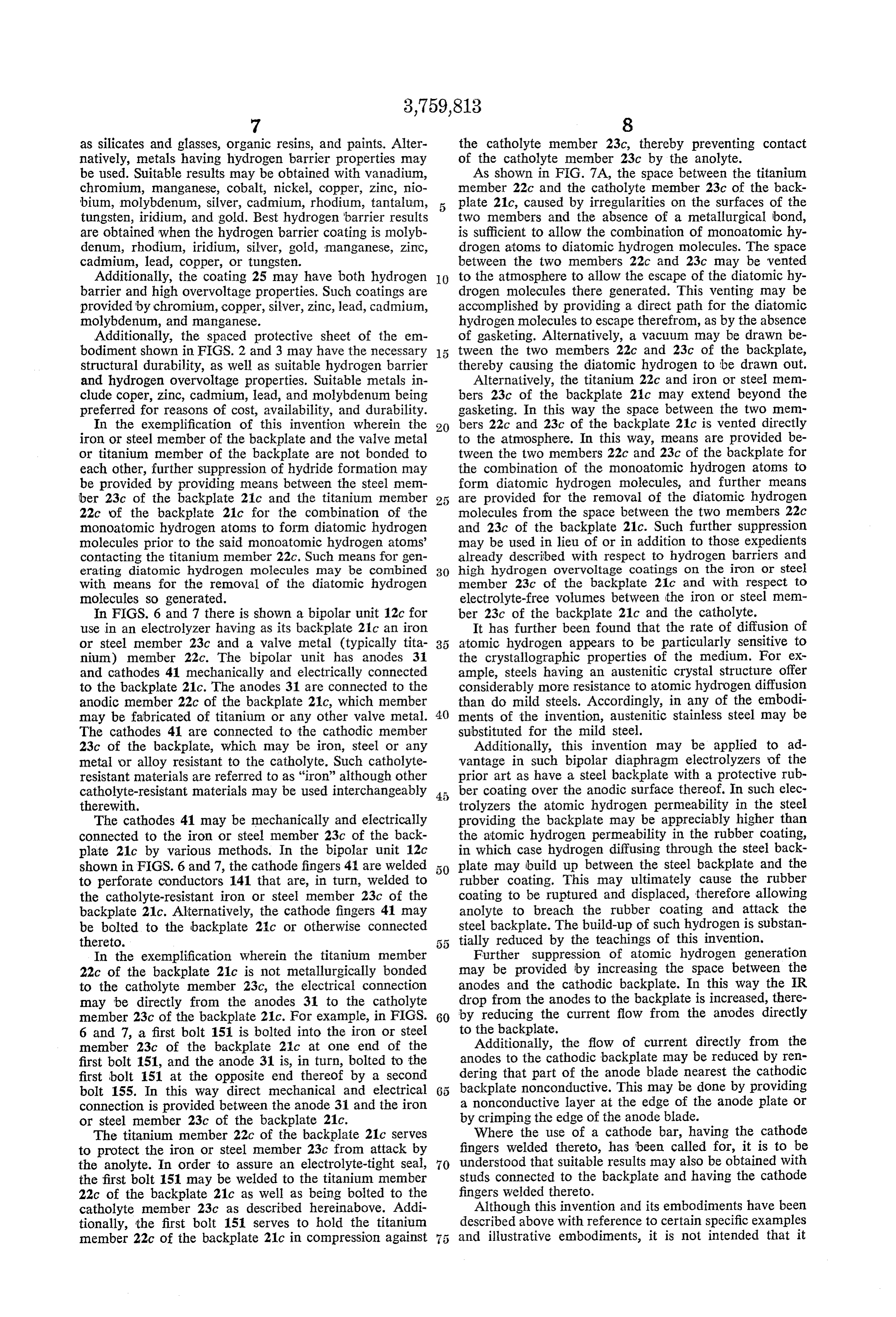
as silicates and glasses, organic resins, and paints. Alter the catholyte member 23c, thereby preventing contact natively, metals having hydrogen barrier properties may of the catholyte member 23c by the anolyte. be used. Suitable results may be obtained with vanadium, As shown in FIG. 7A, the space between the titanium chromium, manganese, cobalt, nickel, copper, zinc, nio member 22c and the catholyte member 23c of the back bium, molybdenum, silver, cadmium, rhodium, tantalum, 5 plate 21c, caused by irregularities on the surfaces of the tungsten, iridium, and gold. Best hydrogen barrier results two members and the absence of a metallurgical bond, are obtained when the hydrogen barrier coating is molyb is sufficient to allow the combination of monoatomic hy denum, rhodium, iridium, silver, gold, manganese, zinc, drogen atoms to diatomic hydrogen molecules. The space cadmium, lead, copper, or tungsten. between the two members 22c and 23c may be vented Additionally, the coating 25 may have both hydrogen O to the atmosphere to allow the escape of the diatomic hy barrier and high overvoltage properties. Such coatings are drogen molecules there generated. This venting may be provided by chromium, copper, silver, zinc, lead, cadmium, accomplished by providing a direct path for the diatomic molybdenum, and manganese. hydrogen molecules to escape therefrom, as by the absence Additionally, the spaced protective sheet of the em of gasketing. Alternatively, a vacuum may be drawn be bodiment shown in FIGS. 2 and 3 may have the necessary 15 tween the two members 22c and 23c of the backplate, structural durability, as well as suitable hydrogen barrier thereby causing the diatomic hydrogen to be drawn out. and hydrogen overvoltage properties. Suitable metals in Alternatively, the titanium 22c and iron or steel mem clude coper, zinc, cadmium, lead, and molybdenum being bers 23c of the backplate 21c may extend beyond the preferred for reasons of cost, availability, and durability. gasketing... In this way the space between the two mem In the exemplification of this invention wherein the 20 bers 22c and 23c of the backplate 21c is vented directly iron or steel member of the backplate and the valve metal to the atmosphere. In this way, means are provided be or titanium member of the backplate are not bonded to tween the two members 22c and 23c of the backplate for each other, further suppression of hydride formation may the combination of the monoatomic hydrogen atoms to be provided by providing means between the steel mem form diatomic hydrogen molecules, and further means ber 23c of the backplate 21c and the titanium member are provided for the removal of the diatomic hydrogen 22c of the backplate 21c for the combination of the molecules from the space between the two members 22c monoatomic hydrogen atoms to form diatomic hydrogen and 23c of the backplate 21c. Such further suppression molecules prior to the said monoatomic hydrogen atoms' may be used in lieu of or in addition to those expedients contacting the titanium member 22c. Such means for gen already described with respect to hydrogen barriers and erating diatomic hydrogen molecules may be combined 30 high hydrogen overvoltage coatings on the iron or steel with means for the removal of the diatomic hydrogen member 23c of the backplate 21c and with respect to molecules so generated. electrolyte-free volumes between the iron or steel mem In FIGS. 6 and 7 there is shown a bipolar unit 12c for ber 23c of the backplate 21c and the catholyte. use in an electrolyzer having as its backplate 2c an iron It has further been found that the rate of diffusion of or steel member 23c and a valve metal (typically tita atomic hydrogen appears to be particularly sensitive to nium) member 22c. The bipolar unit has anodes 31 the crystallographic properties of the medium. For ex and cathodes 41 mechanically and electrically connected ample, steels having an austenitic crystal structure offer to the backplate 21c. The anodes 31 are connected to the considerably more resistance to atomic hydrogen diffusion anodic member 22c of the backplate 21c, which member than do mild steels. Accordingly, in any of the embodi may be fabricated of titanium or any other valve metal. 40 ments of the invention, austenitic stainless steel may be The cathodes 41 are connected to the cathodic member substituted for the mild steel.
23c of the backplate, which may be iron, steel or any Additionally, this invention may be applied to ad metal or alloy resistant to the catholyte. Such catholyte vantage in such bipolar diaphragm electrolyzers of the resistant materials are referred to as "iron” although other prior art as have a steel backplate with a protective rub catholyte-resistant materials may be used interchangeably 45 ber coating over the anodic surface thereof. In such elec therewith, trolyzers the atomic hydrogen permeability in the steel The cathodes 41 may be mechanically and electrically providing the backplate may be appreciably higher than connected to the iron or steel member 23c of the back the atomic hydrogen permeability in the rubber coating, plate 21c by various methods. In the bipolar unit 12c in which case hydrogen diffusing through the steel back shown in FIGS. 6 and 7, the cathode fingers 41 are welded plate may build up between the steel backplate and the to perforate conductors 141 that are, in turn, welded to rubber coating. This may ultimately cause the rubber the catholyte-resistant iron or steel member 23c of the coating to be ruptured and displaced, therefore allowing backplate 21c. Alternatively, the cathode fingers 41 may anolyte to breach the rubber coating and attack the be bolted to the backplate 21c or otherwise connected steel backplate. The build-up of such hydrogen is substan thereto. 55 tially reduced by the teachings of this invention. In the exemplification wherein the titanium member Further suppression of atomic hydrogen generation 22c of the backplate 21c is not metallurgically bonded may be provided by increasing the space between the to the catholyte member 23c, the electrical connection anodes and the cathodic backplate. In this way the IR may be directly from the anodes 31 to the catholyte drop from the anodes to the backplate is increased, there member 23c of the backplate 21c. For example, in FIGS. 60 by reducing the current flow from the anodes directly 6 and 7, a first bolt 151 is bolted into the iron or steel to the backplate.
member 23c of the backplate 21c at one end of the Additionally, the flow of current directly from the first bolt 151, and the anode 31 is, in turn, bolted to the anodes to the cathodic backplate may be reduced by ren first bolt 151 at the opposite end thereof by a second dering that part of the anode blade nearest the cathodic bolt 155. In this way direct mechanical and electrical backplate nonconductive. This may be done by providing connection is provided between the anode 31 and the iron a nonconductive layer at the edge of the anode plate or or steel member 23c of the backplate 21c. by crimping the edge of the anode blade. The titanium member 22c of the backplate 21c serves Where the use of a cathode bar, having the cathode to protect the iron or steel member 23c from attack by fingers welded thereto, has been called for, it is to be the anolyte. In order to assure an electrolyte-tight seal, 70 understood that suitable results may also be obtained with the first bolt 151 may be welded to the titanium member studs connected to the backplate and having the cathode 22c of the backplate 21c as well as being boited to the fingers welded thereto.
catholyte member 23c as described hereinabove. Addi Although this invention and its embodiments have been tionally, the first bolt 151 serves to hold the titanium described above with reference to certain specific examples member 22c of the backplate 21c in compression against and illustrative embodiments, it is not intended that it
Page 10
be so limited thereby except insofar as appears in the 7. The electrolyzer of claim 4 wherein the protective accompanying claims. sheet is steel.
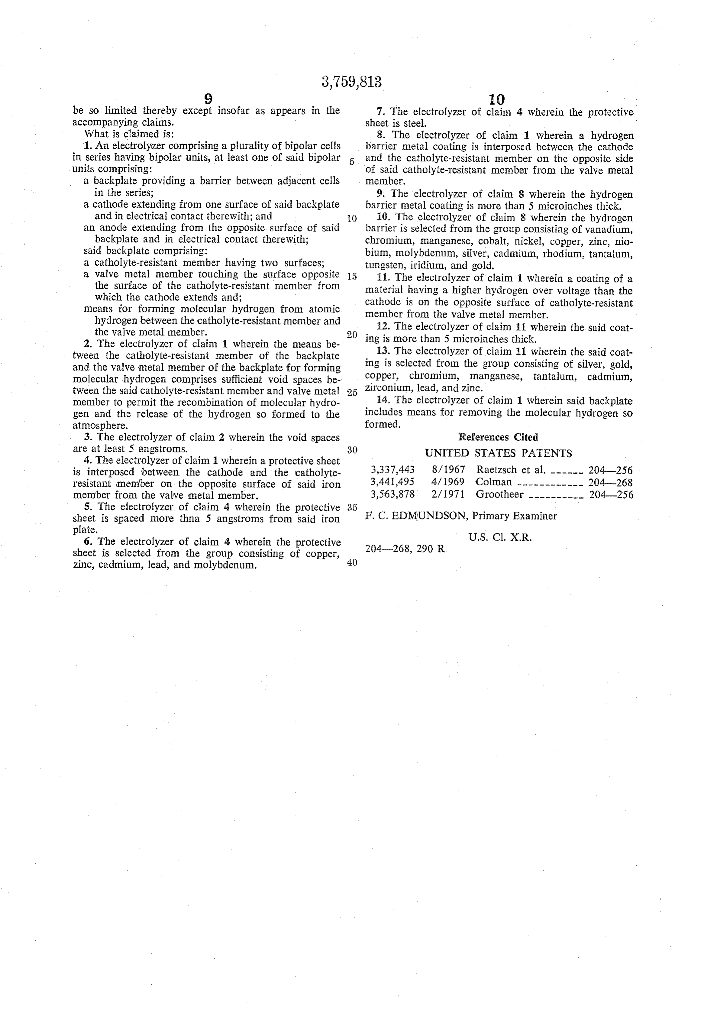
What is claimed is: 8. The electrolyzer of claim wherein a hydrogen 1. An electrolyzer comprising a plurality of bipolar cells barrier metal coating is interposed between the cathode in series having bipolar units, at least one of said bipolar and the catholyte-resistant member on the opposite side units comprising: of said catholyte-resistant member from the valve metal a backplate providing a barrier between adjacent cells member.
in the series; 9. The electrolyzer of claim 8 wherein the hydrogen a cathode extending from one surface of said backplate barrier metal coating is more than 5 microinches thick. and in electrical contact therewith; and () 10. The electrolyzer of claim 8 wherein the hydrogen an anode extending from the opposite surface of said barrier is selected from the group consisting of vanadium, backplate and in electrical contact thereWith; chromium, manganese, cobalt, nickel, copper, zinc, nio said backplate comprising: bium, molybdenum, silver, cadmium, rhodium, tantalum, a catholyte-resistant member having two surfaces; tungsten, iridium, and gold.
a valve metal member touching the surface opposite 5 ii. The electrolyzer of claim 1 wherein a coating of a the surface of the catholyte-resistant member from material having a higher hydrogen over voltage than the which the cathode extends and; cathode is on the opposite surface of catholyte-resistant means for forming molecular hydrogen from atomic member from the valve metal member. hydrogen between the catholyte-resistant member and 12. The electrolyzer of claim 11 wherein the said coat the valve metal member. 20 2. The electrolyzer of claim 1 wherein the means be ing is more than 5 microinches thick. tween the catholyte-resistant member of the backplate 13. The electrolyzer of claim 11 wherein the said coat and the valve metal member of the backplate for forming ing is selected from the group consisting of silver, gold, molecular hydrogen comprises sufficient void spaces be copper, chromium, manganese, tantalum, cadmium, tween the said catholyte-resistant member and valve metal Zirconium, lead, and zinc.
member to permit the recombination of molecular hydro i4. The electrolyzer of claim 1 wherein said backplate gen and the release of the hydrogen so formed to the includes means for removing the molecular hydrogen so atmosphere. formed.
3. The electrolyzer of claim 2 wherein the void spaces References Cited are at least 5 angstroms. 30 UNITED STATES PATENTS 4. The electrolyzer of claim 1 wherein a protective sheet is interposed between the cathode and the catholyte 3,337,443 8/1967 Raetzsch et al. ------ 204-256 resistant member on the opposite surface of said iron 3,441,495 4/1969 Colman ------------ 204-268 member from the valve metal member. 3,563,878 2/1971 Grootheer ---------- 204-256 5. The electrolyzer of claim 4 wherein the protective 3.: 5 sheet is spaced more thina 5 angstroms from said iron F. C. EDMUNDSON, Primary Examiner plate.
6. The electrolyzer of claim 4 wherein the protective U.S. Cl. X.R. sheet is selected from the group consisting of copper, 204-268, 290 R zinc, cadmium, lead, and molybdenum. 40
Provenance
- Collection
- Cited prior art
- Original PDF
- patentimages.storage.googleapis.com →
- Filed
- 1971-07-01
- Pages
- 10
- Method
- pdftotext (the PDF's own text layer) + pdftoppm 300dpi page scans
- Source
- Google Patents bibliographic record
- Granted
- 1973-09-18
- Inventors
- C Raetzsch; W Darlington; H Cunningham; PPG Industries Inc
- Transcribed from
- patentimages.storage.googleapis.com →