patent · US3963327
Device for operating frusto-conical optical concentrators
15 June 1976
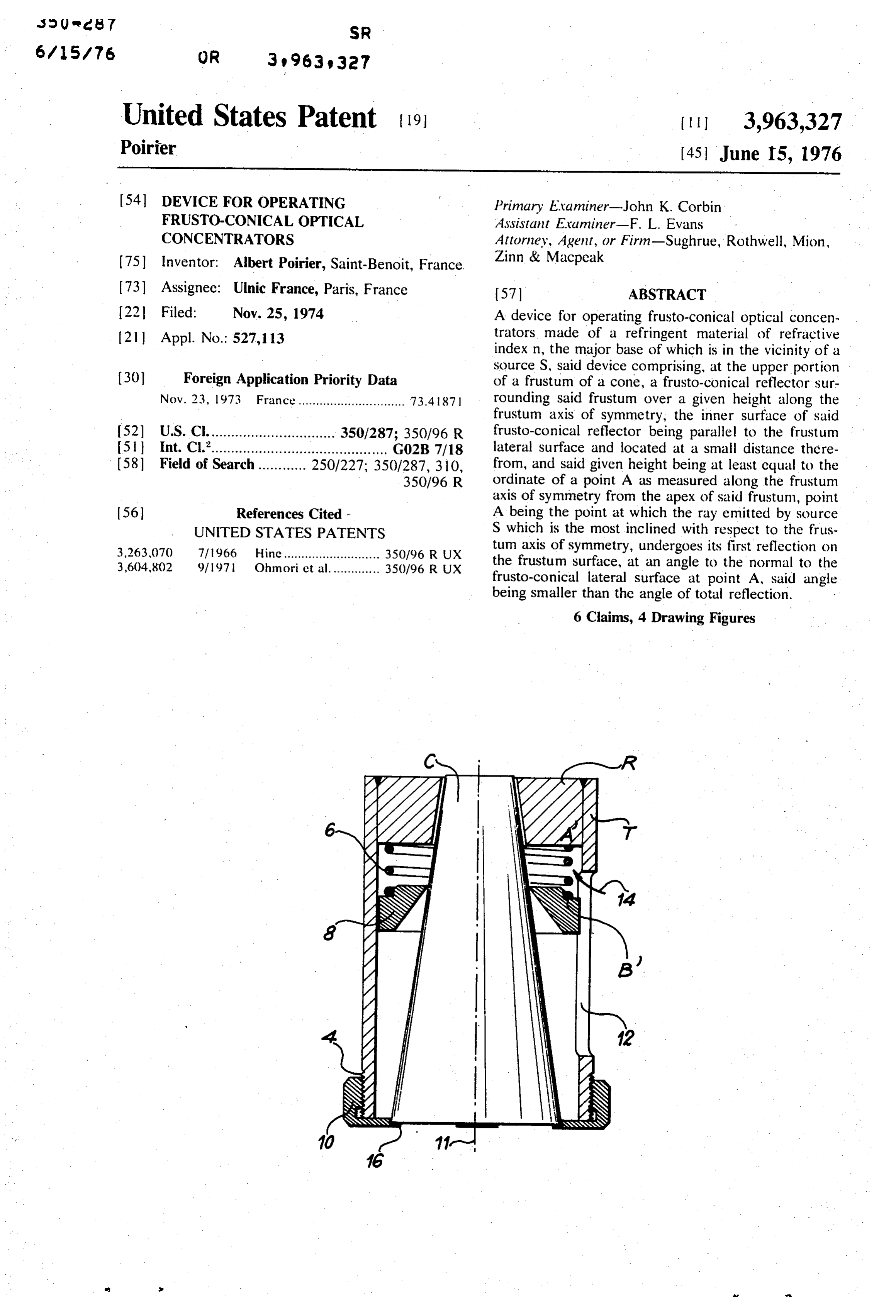
Page 1 — bibliographic record
so U re. I SR
United States Patent (19) 3,963,327 Poirier
(54) DEVICE FOR OPERATING Primary Examiner-John K. Corbin FRUSTO-CONICAL OPTICAL Assistant Examiner-F. L. Evans
CONCENTRATORS Attorney, Agent, or Firm-Sughrue, Rothwell, Mion, 75 inventor: Albert Poirier, Saint-Benoit, France. Zinn & Macpcak 73 Assignee: Ulnic France, Paris, France 57 ABSTRACT (22 Filed: Nov. 25, 1974 A device for operating frusto-conical optical concen (21) Appl. No. 527,113 trators made of a refringent material of refractive index n, the major base of which is in the vicinity of a source S, said device comprising, at the upper portion 30 Foreign Application Priority Data of a frustum of a cone, a frusto-conical reflector sur Nov. 23, 1973 France.............................. 73487 rounding said frustum over a given height along the frustum axis of symmetry, the inner surface of said 52 U.S. Cl................................ 350/287; 350/96 R frusto-conical reflector being parallel to the frustum (51 Int. Cl.'............................................ G02B 7/18 lateral surface and located at a small distance the re (58. Field of Search............ 250/227; 350/287, 310, from, and said given height being at least cqual to the 350/96 R ordinate of a point A as measured along the frustum axis of symmetry from the apex of said frustum, point 56 References Cited - A being the point at which the ray emitted by source UNITED STATES PATENTS S which is the most inclined with respect to the frus 3.263,070 7/1966 Hine........................... 350/96 R UX tum axis of symmetry, undergoes its first reflection on 3,604,802 9/97. Ohmori et al.............. 350/96 R UX the frustum surface, at an angle to the normal to the frusto-conical lateral surface at point A, said angle being smaller than the angle of total reflection.
6 Claims, 4 Drawing Figures
Page 2
Drawing sheet — no readable text.
Page 3
Drawing sheet — no readable text.
Page 4
Therefore, according to the invention, reflector R,
DEVICE FOR OPERATING FRUSTO-CONICAL e.g. of metal, is mounted in such a manner that all the OPTICAL CONCENTRATORS rays intersecting the lateral surface of frustum C un dergo a reflection on reflector R and are re-directed
The present invention relates to a device for operat 5 toward frustum C. This improvement permits to save a ing frusto-conical optical concentrators. substantial portion of the light energy which, being As is well known, frusto-conical optical concentra recovered within frustum C, is emitted through the tors constituted by a frustum of a cone defined by two minor base of said frustum, and, moreover, these rays plane surfaces (or buses) form the object of a number O neither of industrial applications, in particular as regards the paths atdazzle more nor heat any object located along their or less uncontrolled angles. The frusto concentration of the light-rays emitted by a source conical internal surface (e.g. of metal) of reflector R is situated along the frustum axis of symmetry, in the specularly polished in order that absorption and diffu vicinity of the major base. The dimensions of the frus sion be minimal.
tum should comply with their destination: the length and the vertex angle gamma of said frustum of a cone 5 tumReflector R is mounted at a small distance from frus are selected according to the nature of the source, to gentlyC,allowed in order that pressurized air may be contin to flow with a view to cooling the frus the angular aperture of the rays that impinge on the tum and major base and to the constant-flux maximum concen immersion phenomenonreflector R and, moreover, for avoiding the tration or optimal illumination which it is desired to said which would happen should achieve on the minor base of the frusto-conical optical 20 metal reflector R be in intimate contact with the concentrator. For more detailed information relating to surface of frustum C. In the latter case, indeed, the such optical concentrators, it is suggested to refer to index n' corresponding to the metal reflector being U.S. Pat. No. 3,535,016 corresponding to French Pat. different from unity, the angle of total reflection would No. 1,543,165 and also to the inventor's thesis entitled no longer be given by the relation "Maximum optical concentration in radiation receivers 25 sin A = (1/n optimized conical mirrors."
When intense sources S are involved, it is often advis respect tois the wherein the total reflection angle measured with normal to the interface between two able to channel the light rays which may happen to escape through the frustum walls; moreover, it is neces media having different indices, but by the relation sary to maintain that frustum of a cone in a fixed posi 30 sin A = (n'in) tion relative to the source without, on the one hand, damaging said frustum by means of too rigid clamping since n' is higher than unity, the critical angle M corre devices, likely to undergo thermal expansion due to the sponding important heat-flux emitted by the source, which would would be to total reflection in the case of immersion generate too large stresses in the refringent material 35 dergo total reflectionsobetween increased, that many rays adapted to un forming said frustum and would lead to the formation index n and a medium of indexa medium of refractive equal to unity (air), of cracks, and, on the other hand, so that the materials would no longer undergo total reflection, firmly supporting and maintaining said frustum can be detrimental since a portion of the which would
withstand the important heat-flux emitted by the would be absorbed by the metal.
source without failing. More specifically, the invention 40 Should index n' be a complex number, the real part relates to a device for operating frusto-conical optical thereof concentrators made of a refringent material with a to avoidwould total be used in the above formulas. In order reflection it is necessary that the spacing refractive index n and the major base of which is in the between the two media of respective indices n and n', vicinity of a source S, said device being adapted to 45 should be greater than several times the wave-length of maintain the optical concentrator fixed with respect to said source under suitable conditions, to cool the metal the light involved.
parts located in the vicinity of a portion of the surface This explains why a spacing of the order of a millime thereof and to optimize the flux issuing from the minor that ter between frustum C and reflector R perfectly meets base of frustum C. requirement, while permitting a cooling gas con The device according to the invention is character 50 tingently used to flow between the frustum and the ized in that it comprises a frusto-conical reflector R at reflector.
of height
It is possible, in theory, to calculate the value 1, assuming one knows the position of source the upper portion of frustum C. Said reflector R sur rounds the concentrator along a height 1 measured S, the value of the apex angle y of frustom C and the along the frustum axis of symmetry; the inner surface of aperture 6 of the beam impinging the major base of said reflector R, of frusto-conical shape, is parallel with the 55. frustum.
outer surface of frustum C and the spacing between the As regards that theoretical calculation, reference will two frustums is small (viz about a few milimmeters at advantageously be had to pages 190 and sq. of the most, and at least a few tenths of a millimeter). above mentioned thesis.
Height 1 of reflector R, as measured along the frus 60 In specific cases, it is also possible to resort to the tum axis of symmetry and reckoned from the frustum sometimes easier graphical construction, consisting in minor base, is at least equal to the ordinate of point A, drawing the path of the ray having the maximum incli as measured along the frustum axis of symmetry from nation with respect to the entrance face of the frustum, the apex of said frustum of a cone. Point A is the one at and to measure the ordinate of point A at which reflec which a ray Remitted by source S (and most slanted 65 tion is not total.
with respect to the frustum axis of symmetry) under According to a preferred embodiment, the device goes a first reflection on the frustum surface, at an comprises:
angle to the normal to the lateral surface of the frustum a cylindrical tube T, externally threaded at the lower at point A smaller than the total reflection angle. portion thereof, to which is attached reflector R,
Page 5
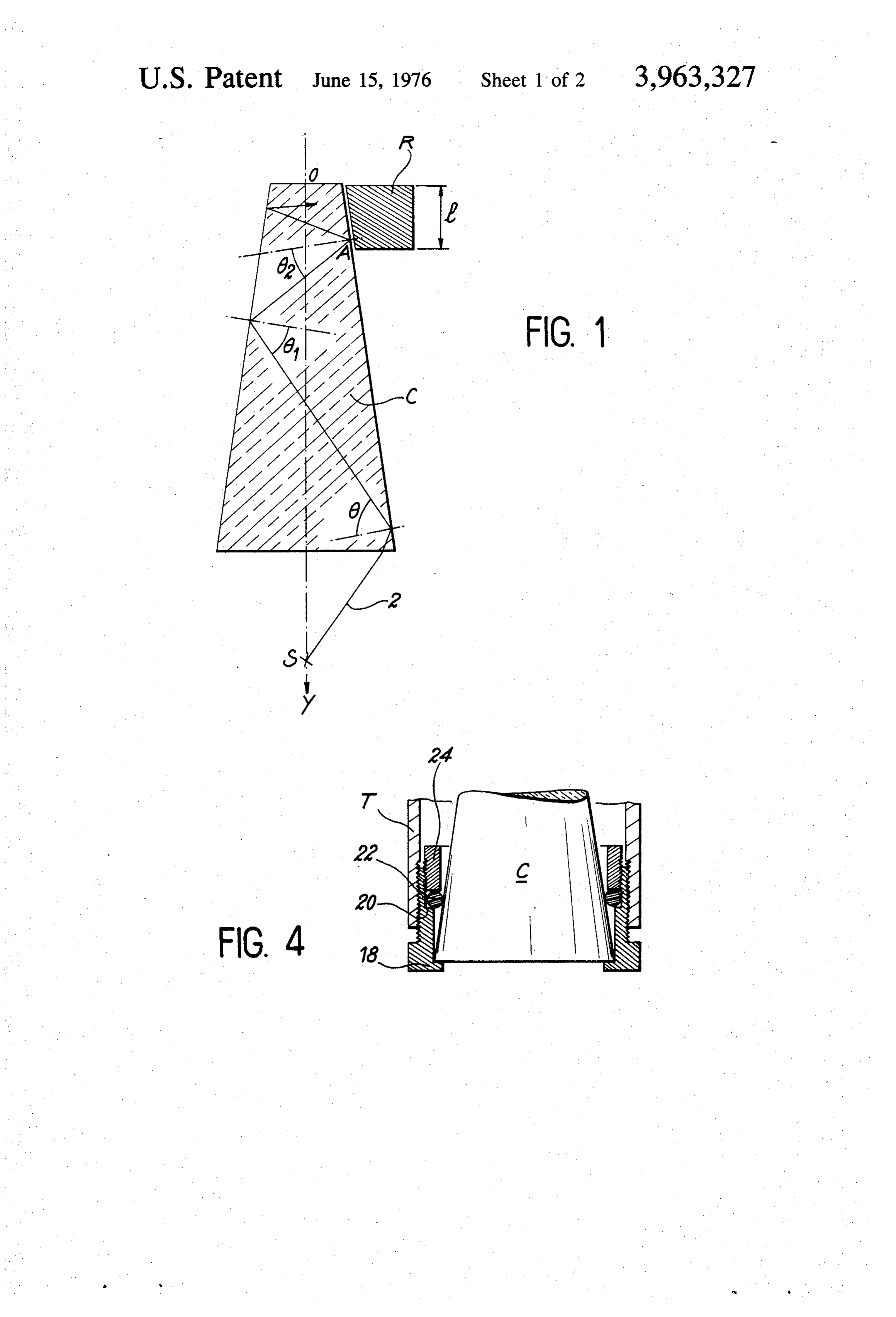
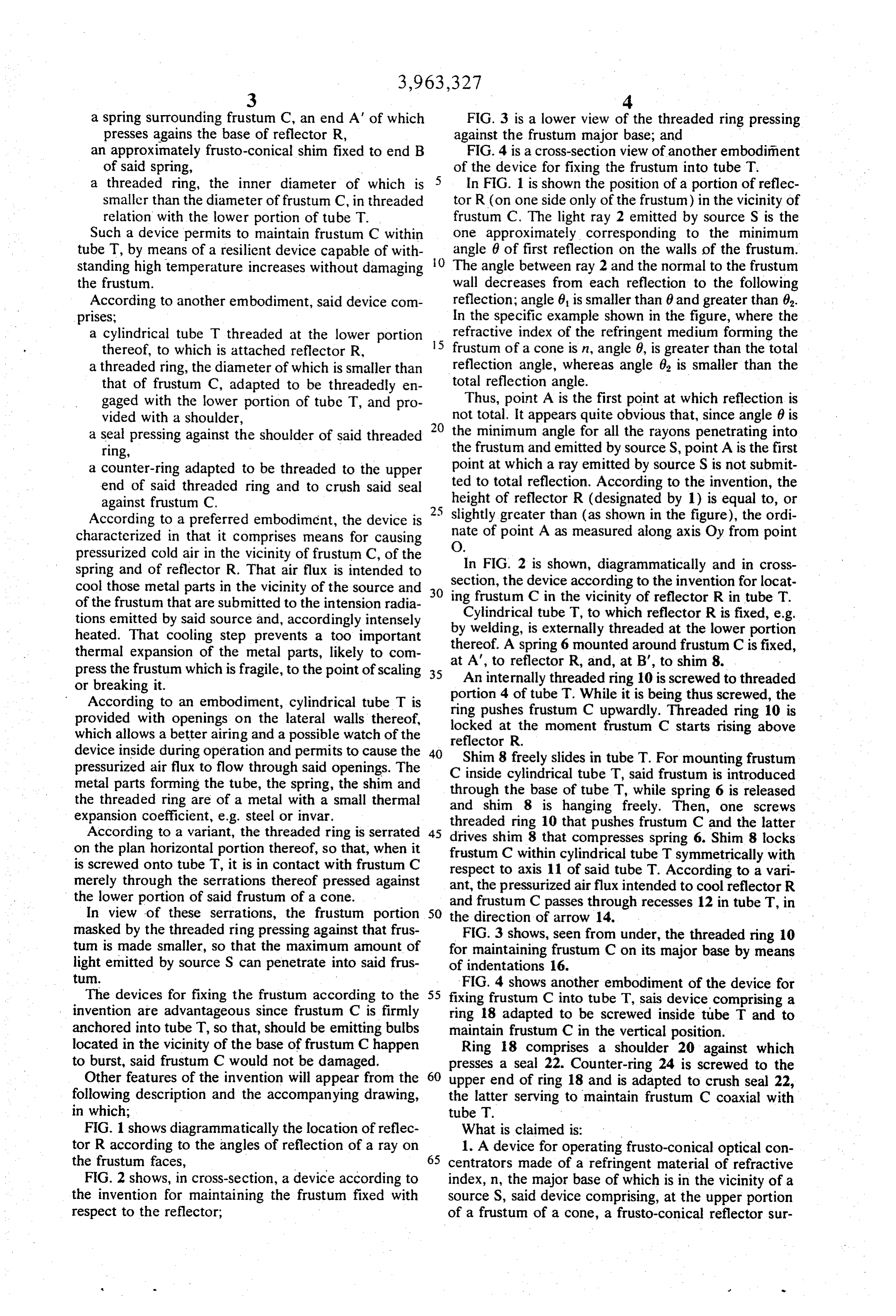
a spring surrounding frustum C, an end A' of which FIG. 3 is a lower view of the threaded ring pressing presses agains the base of reflector R, against the frustum major base; and an approximately frusto-conical shim fixed to end B FIG. 4 is a cross-section view of another embodiment of said spring, of the device for fixing the frustum into tube T. a threaded ring, the inner diameter of which is 5 In FIG. 1 is shown the position of a portion of reflec smaller than the diameter of frustum C, in threaded tor R (on one side only of the frustum) in the vicinity of relation with the lower portion of tube T. frustum C. The light ray 2 emitted by source S is the Such a device permits to maintain frustum C within one approximately corresponding to the minimum tube T, by means of a resilient device capable of with O angle 6 of first reflection on the walls of the frustum. standing high temperature increases without damaging The angle between ray 2 and the normal to the frustum the frustum. wall decreases from each reflection to the following According to another embodiment, said device com reflection; angle 0, is smaller than 0 and greater than 0. prises; In the specific example shown in the figure, where the a cylindrical tube T threaded at the lower portion 15 refractive index of the refringent medium forming the thereof, to which is attached reflector R, frustum of a cone is n, angle 6, is greater than the total a threaded ring, the diameter of which is smaller than reflection angle, whereas angle 6, is smaller than the that of frustum C, adapted to be threadedly en total reflection angle.
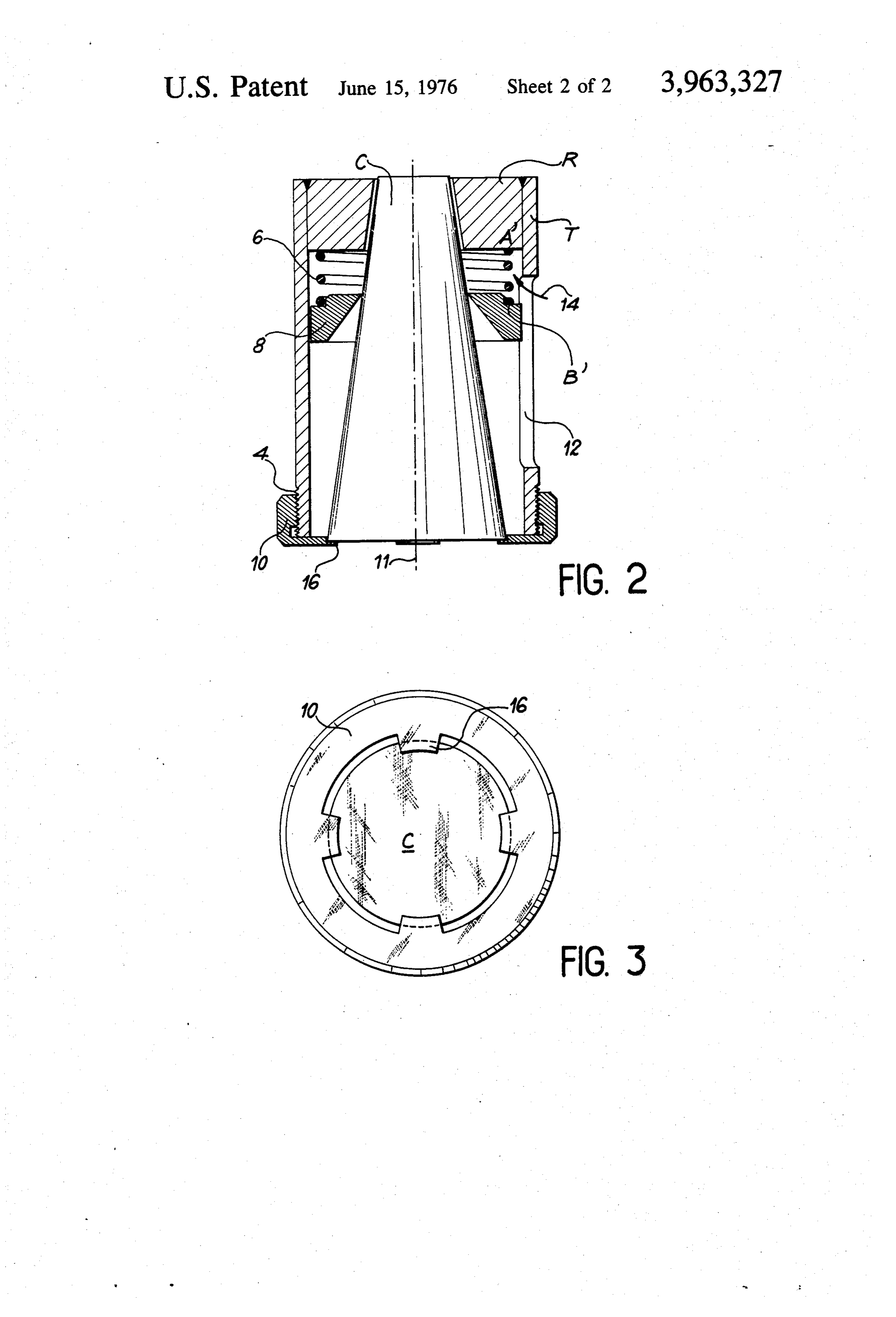
gaged with the lower portion of tube T, and pro Thus, point A is the first point at which reflection is vided with a shoulder, not total. It appears quite obvious that, since angle 6 is a seal pressing against the shoulder of said threaded 20 the minimum angle for all the rayons penetrating into ring, the frustum and emitted by source S, point A is the first a counter-ring adapted to be threaded to the upper point at which a ray emitted by source S is not submit end of said threaded ring and to crush said seal height ted to total reflection. According to the invention, the against frustum C. 25 of reflector R (designated by 1) is equal to, or According to a preferred embodiment, the device is 5 slightly greater than (as shown in the figure), the ordi characterized in that it comprises means for causing O. nate of point A as measured along axis Oy from point pressurized cold air in the vicinity of frustum C, of the In FIG. 2 is shown, diagrammatically and in cross spring and of reflector R. That air flux is intended to section, the device according to the invention for locat cool those metal parts in the vicinity of the source and so of the frustum that are submitted to the intension radia ing frustum C in the vicinity of reflector R in tube T. tions emitted by said source and, accordingly intensely Cylindrical tube T, to which reflector R is fixed, e.g. heated. That cooling step prevents a too important by welding, is externally threaded at the lower portion thereof. A spring 6 mounted around frustum C is fixed, thermal expansion of the metal parts, likely to com at A', to reflector R, and, at B', to shim 8. press the frustum which is fragile, to the point of scaling 35 An internally threaded ring 10 is screwed to threaded or breaking it.
According to an embodiment, cylindrical tube T is portion 4 of tube T. While it is being thus screwed, the ring pushes frustum C upwardly. Threaded ring 10 is provided with openings on the lateral walls thereof, locked which allows a better airing and a possible watch of the reflectoratR.the moment frustum C starts rising above device inside during operation and permits to cause the 40 Shim 8 freely slides in tube T. For mounting frustum pressurized air flux to flow through said openings. The C inside cylindrical tube T, said frustum is introduced metal parts forming the tube, the spring, the shim and through the threaded ring are of a metal with a small thermal and shimthe8base is of tube T, while spring 6 is released hanging freely. Then, one screws expansion coefficient, e.g. steel or invar.
According to a variant, the threaded ring is serrated 45 drives shim 8 that compressesfrustum threaded ring 10 that pushes C and the latter spring 6. Shim 8 locks on the plan horizontal portion thereof, so that, when it frustum C within cylindrical tube T symmetrically with is screwed onto tube T, it is in contact with frustum C merely through the serrations thereof pressed against respect to axis 11 of said tube T. According to a vari ant, the pressurized air flux intended to cool reflector R the lower portion of said frustum of a cone. and frustum C passes through recesses 12 in tube T, in In view of these serrations, the frustum portion 50 the direction of arrow 14. , masked by the threaded ring pressing against that frus FIG. 3 shows, seen from under, the threaded ring 10 tum is made smaller, so that the maximum amount of for maintaining frustum C on its major base by means light emitted by source S can penetrate into said frus of indentations 16.
tum. FIG. 4 shows another embodiment of the device for The devices for fixing the frustum according to the 55 fixing frustum C into tube T, sais device comprising a invention are advantageous since frustum C is firmly ring 18 adapted to be screwed inside tube T and to anchored into tube T, so that, should be emitting bulbs maintain frustum C in the vertical position. located in the vicinity of the base of frustum Chappen Ring 18 comprises a shoulder 20 against which to burst, said frustum C would not be damaged. presses a seal 22. Counter-ring 24 is screwed to the Other features of the invention will appear from the 60 upper end of ring 18 and is adapted to crush seal 22, following description and the accompanying drawing, the latter serving to maintain frustum C coaxial with in which; tube T.
FIG. 1 shows diagrammatically the location of reflec What is claimed is:
tor R according to the angles of reflection of a ray on 1. A device for operating frusto-conical optical con the frustum faces, 65 centrators made of a refringent material of refractive FIG. 2 shows, in cross-section, a device according to index, n, the major base of which is in the vicinity of a the invention for maintaining the frustum fixed with source S, said device comprising, at the upper portion respect to the reflector; of a frustum of a cone, a frusto-conical reflector sur
Page 6
rounding said frustum over a given height along the a counter-ring adapted to be threaded to the upper frustum axis of symmetry, the inner surface of said end of said threaded ring and to crush said seal frusto-conical reflector being parallel to the frustum against frustum.
lateral surface and located at a small distance there 3. A device according to claim 1 wherein the appara from, and said given height being at least equal to the 5 tus for positioning said reflector comprises: ordinate of a point A as measured along the frustum a cylindrical tube, externally threaded at the lower axis of symmetry from the apex of said frustum, point A portion thereof, to which is attached a reflector, being the point at which the ray emitted by source S, a spring surrounding frustum, an end of which which is the most inclined ray with respect to the frus O presses against the base of said reflector, tum axis of symmetry, undergoes its first reflection on an approximately frusto-conical shim fixed to end of the frustum surface at an angle to the normal to the said spring, frusto-conical lateral surface at point A, said angle a threaded ring, the inner diameter of which is being smaller than the angle of total reflection. smaller than the diameter of said frustum, in 2. A device according to claim 1, wherein the appara 15 4. threaded relation with the lower portion of tube. A device according to claim 2, comprising means tus for positioning said reflector comprises:
a cylindrical tube threaded at the lower portion for causing pressurized cold air to flow in the vicintiy of said frustum of a cone and of said reflector.
thereof, to which is attached a reflector, 5. A device according to claim 4, wherein said cylin a threaded ring, the diameter of which is smaller than drical tube comprises openings in the lateral walls of frustum, adapted to be threadedly engaged with 20 thereof.
the lower portion of tube and provided with a 6. A device according to claim 2, wherein said shoulder, threaded ring is serrated in the plane horizontal portion a seal pressing against the shoulder of said threaded thereof.
ring, xk ck xk ck xk
Provenance
- Collection
- Cited prior art
- Original PDF
- patentimages.storage.googleapis.com →
- Filed
- 1974-11-25
- Pages
- 6
- Method
- pdftotext (the PDF's own text layer) + pdftoppm 300dpi page scans
- Source
- Google Patents bibliographic record
- Granted
- 1976-06-15
- Inventors
- Albert Poirier; ULNIC FRANCE
- Transcribed from
- patentimages.storage.googleapis.com →