patent · US4035170
Granular filter
12 July 1977
Page 1 — bibliographic record
United States Patent (19) (11) 4,035,170 Lear, Jr. et al. (45) July 12, 1977 (54) GRANULAR FILTER 3,868,237 2/1975 Berz .................................... 55/283 3,920,427 1 1/1975 Lachnit ............................... 55/479 (75) Inventors: Dean Everett Lear, Jr., Scott's
Valley; Alan Howard Schmid, Santa FOREIGN PATENT DOCUMENTS
Cruz; Henry Ford Harding Wigton, 554,893 7/1932 Germany ............................. 551290 Palo Alto, all of Calif. 216,675 6/1924 United Kingdom ................. 55/474 73) Assignee: The United States of America as 879,216 10/1961 United Kingdom ................. 55/474 represented by the Administrator of Primary Examiner-Bernard Nozick
Environmental Protection Agency,
Washington, D.C. 57 ABSTRACT (21) Appl. No.: 647,471 A continuously regenerating granular filter operable at 22 Filed: Jan. 8, 1976 high temperature and pressure includes a filter cham ber with a gas inlet and gas outlet. A filter bed in the (51 int. Cl’......................................... B01D 46/32 chamber located between the gas inlet and gas outlet is (52) U.S. C. ................................... 55/267; 55/282; adapted to hold a filter medium and permit gas to flow 55/474; 55.1479; 165/106; 432/215 therethrough. The filter bed includes inlet means and (58) Field of Search ......................... fo see see 55/77-79, outlet means for enabling the filter medium to move 55/98, 99,474, 479, 282,302,301,283,267; through the filter bed. The filter also includes filter 165/106; 432/215 medium cleaning means for cleaning the filter medium.
(56) References Cited Filter medium transport means operates to transport
the filter means from the outlet means, through the cleaning means and to the inlet means.
2,684,124 7/1954 Hines, Jr. ................. v 8 a w 55179 14 Claims, 5 Drawing Figures
Page 2
Drawing sheet — no readable text.
Page 3
Drawing sheet — no readable text.
Page 4
Drawing sheet — no readable text.
Page 5
small particles of the filtering medium entrained in the
GRANULAR FILTER flowing gas, which would cause deposit buildup and erosion to the turbine blades. m
BACKGROUND OF THE INVENTION The preferred filter medium is a high temperature The invention described and claimed in this applica resistant, ceramic material which is physically inert at tion relates to granular filters and, more particularly, to temperatures ranging as high as 1500 F-2000' F; such continuously regenerate granular filters operatable at material has a hardness of greater than 8 on the Mohs high temperature and pressure which are particularly hardness scale.
suited for cleaning gas used to operate a gas turbine. The filtering system includes a filter chamber into With the current shortage of many fuels which have 10 which the gas to be cleaned is circulated. The chamber traditionally been used to generate heat and power, contains the filtering medium through which the gas electric generating plants using coal with high impurity flows and is cleaned. The filtering medium can continu and ash levels and other solid fuels are playing an ever ously be moved throught the filter chamber so that the increasing role in supplying electric power. Other solid filter does not have to be stopped for cleaning. A media fuels may include, for example, combustible solid 15 entrainment chamber is provided where the filter me wastes such as trash, rubbish, garbage, agricultural dium is entrained with gas under pressure. The medium residues, and industrial residues. It has been found that is moved by means of the entrained gas into a de gas streams formed by burning such fuels contain a entrainment relatively high concentration of fine particles matter and the filtervessel medium where the entrained gas is vented is moved to a cleaning chamber.
which must be removed in order for the system to oper 20 In the cleaning chamber a counter-flow cascade ar ate efficiently and effectively. Of particular impor rangement is provided where gas is circulated in the tance, is a system utilizing a turbine generator in which direction opposite to that in which the hot pressurized gas can be cleaned without signifi ing for loosening ash on the filteringthe medium is mov medium so that the cantly lowering the temperature or pressure of the gas. ash can be carried away in the counter-flowing gas. The Different types of filters or separators have been 25 cleaned medium then flows into a slugging fluid tried, but many have significant drawbacks which pre where the final removal of the ash takes place by bed vent them from being used. For example, inertial sepa flowing through the medium. The level of mediumgasis rators such as cyclones have been found not to be ef maintained within a pre-selected range for continuous fective in removing micron or sub-micron size particles redistribution into the filter chamber. and since cyclones operate at a relatively high velocity, 30 The filter chamber e.g. 50-150 feet/second, if the particulate material has velocity is required tois effect designed so that minimum gas filtration, which in turn a tendency to stick to surfaces dense deposits in the minimizes the pressure loss due to the gas flowing cyclone result.
Bag houses, where the gas is channeled through a leading to and from the medium andinreduces through filter medium. This results smaller openings finely meshed material to filter out the particulate ma bility of particles of the filter medium beingthecarried 35 possi terial, are limited to relatively low temperatures be downstream by the gas. In addition, this relatively low cause of the material used to form the bag. In addition, bag houses are not effective at velocities greater than velocity results in a porous low density ash buildup at 15 feet/min., which would require an excessively large the inlet to the filter material (as opposed to the dense filter area at great cost. 40 hard buildup caused by a high velocity), which is easily Electrostatic precipitators have found not to be ef removed.
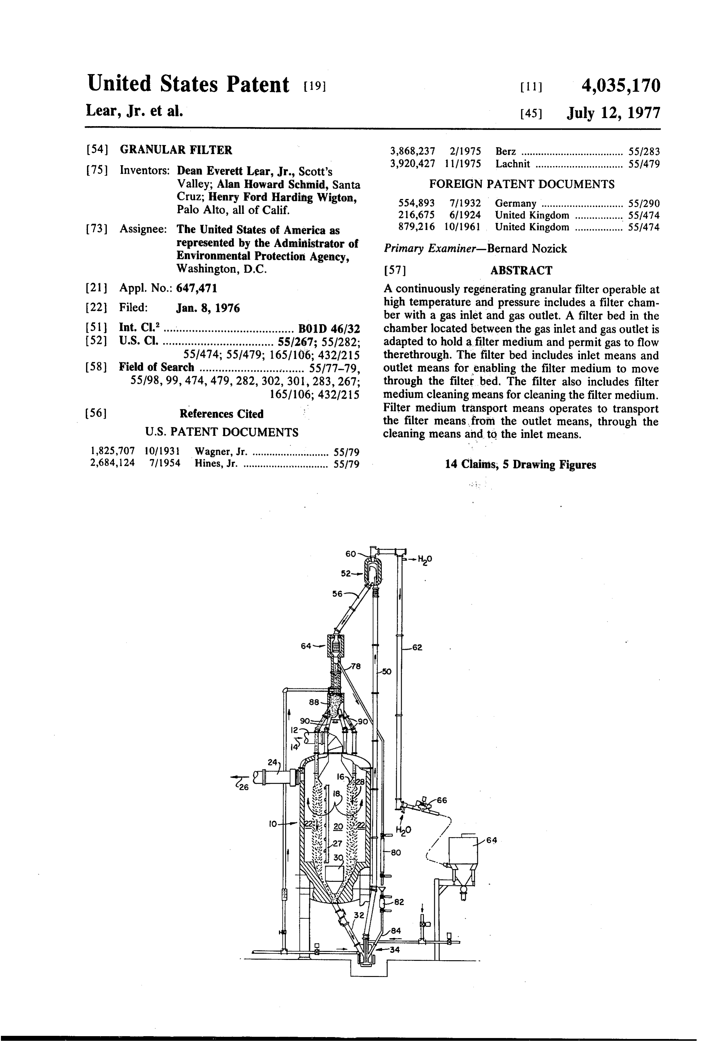
fective because of their relatively large size and com BRIEF DESCRIPTION OF THE DRAWINGs plex construction. In addition, electrostatic precipita tors consume relatively high amounts of power and are For a better understanding of the invention, refer sensitive to electrical properties of the particulate ma 45 ence may be had to the following description of a pre terial to be removed from the gas. Although electro ferred embodiment, taken in conjunction with the ac static precipitators have a relatively high maximum companying drawings, in which:
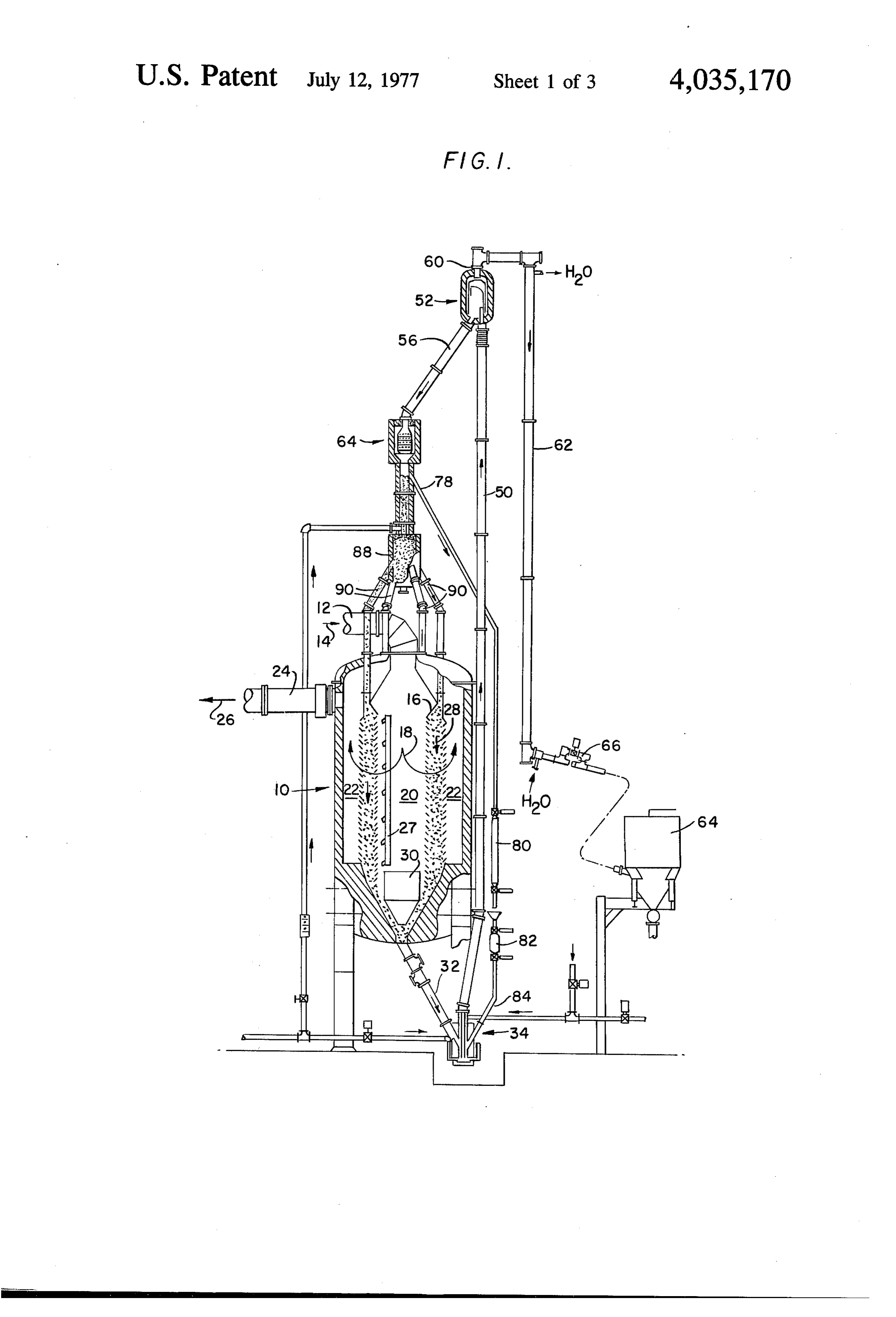
collection efficiency, the overall collection efficiency is FIG. 1 is a diagrammatic view of the overall filter not as great because of uneven gas flow distribution assembly;
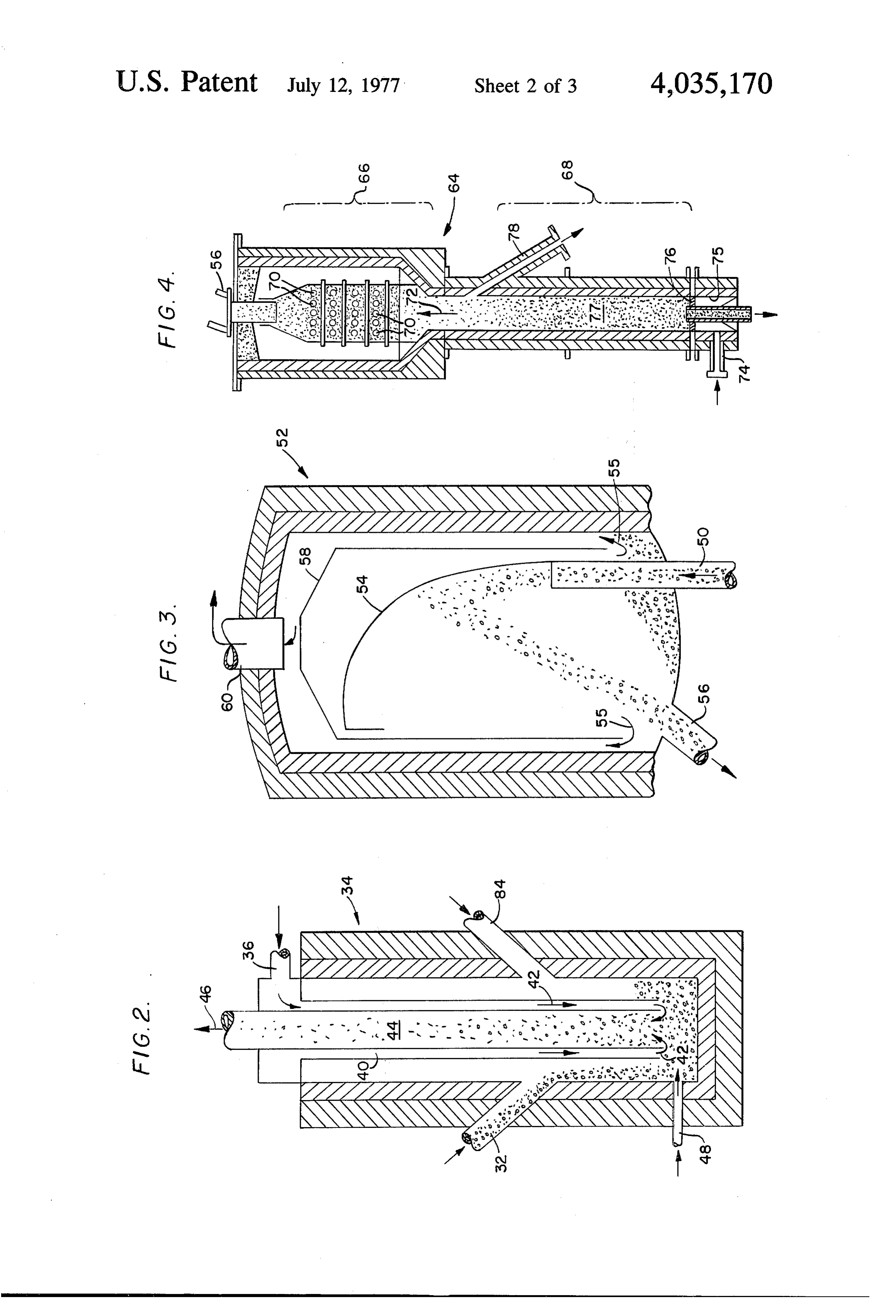
and particulate re-entrainment when the plates are 50 FIG. 2 is an enlarged sectional view of the entrain cleaned. ment chamber shown in FIG. 1; It has been found that filters using a granular material FIG. 3 is an enlarged sectional view of the deentrain as a filter medium offer significant advantages for use ment chamber shown in FIG. 1;
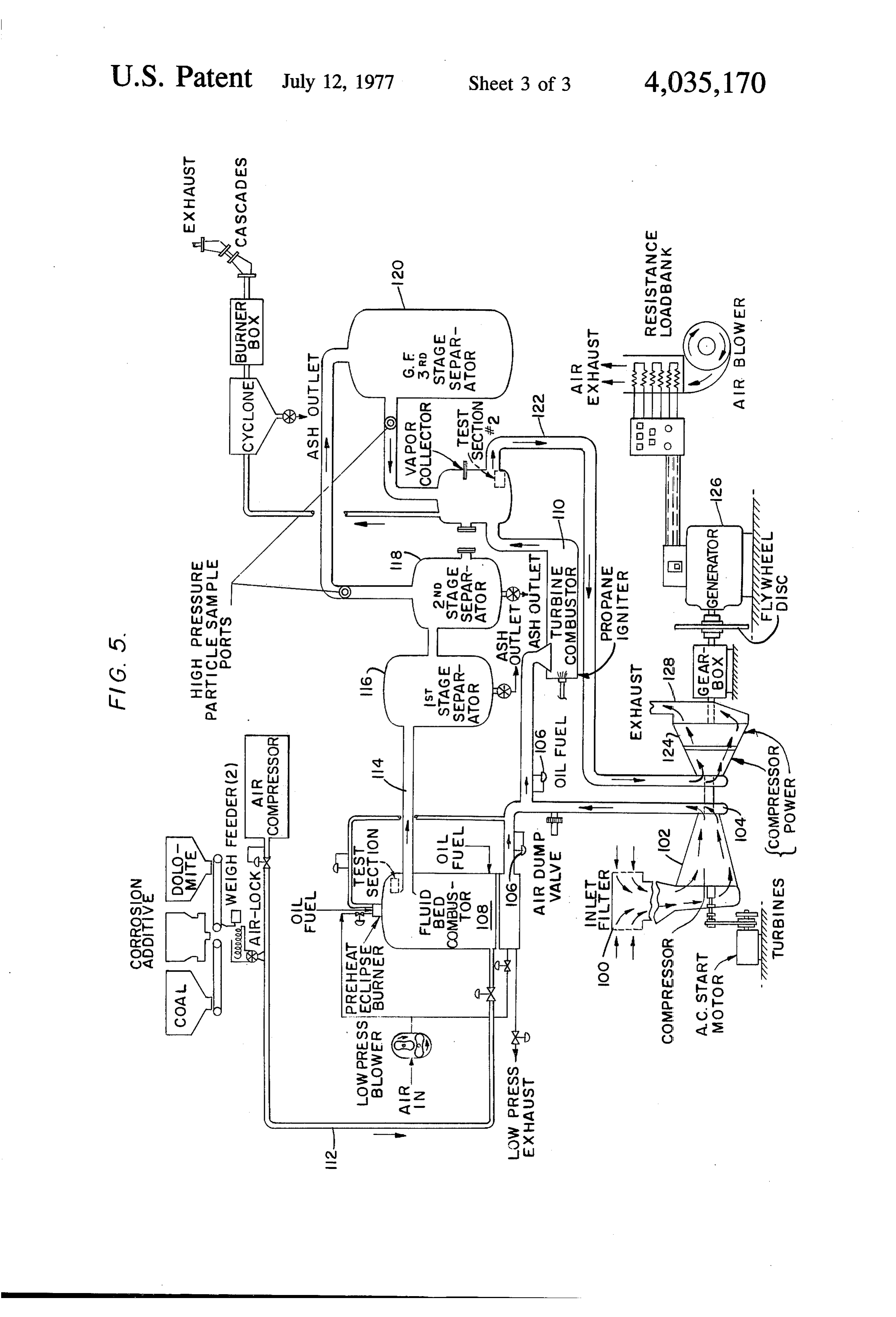
in a high temperature and pressure environment where FIG. 4 is an enlarged sectional view of the media high efficiency cleaning is necessary. However, no 55 cleaning chamber assembly shown in FIG. 1; and granular filters were known which operated continu FIG. 5 is a diagrammatic view of a gas turbine system ously and efficiently for long periods of time under in which the novel granular filter can be used. such conditions of high pressure and temperature.
DETAILED DESCRIPTION OF A PREFERRED
SUMMARY OF THE INVENTION 60 EMBODIMENT
A granular filter is provided, in accordance with the Now, a detailed description of a preferred embodi invention, which operates effectively at high tempera ment of the inventive granular filter will be described in ture and pressure and which solves the problems dis detail in conjunction with the drawings. cussed above. ... : . Referring to FIG. 1, a diagrammatic view of the gran The filter is of relatively small size and by nature of 65 ular filter is shown where the filter chamber is desig its operation couples high filtering efficiency with max nated by reference numeral 10. The filter chamber 10 imum practicable protection to downstream equipment includes the annular filter bed 16 which contains the from ash from combustion of the solid fuel and from filtering medium.
Page 6
The filter medium is preferably, aluminum oxide spill from the inlet face of the annular filter bed to enter spheres which are approximately 0.08 inches in diame the outlet pipe. The outlet pipe 32 also operates to seal ter. However, other materials which are resistant to the chamber 10 and prevent gas from leaking from the high temperatures and physically, inert at approxi circulation system into the filter.
mately 1500-2000 F with a hardness of greater than 8 5 The medium flows from the outlet pipe 32 into the on the Mohs' hardness scale could also be used, for entrainment chamber 34 which is shown in greater example, material such as silicon carbide ceramic ma detail in FIG. 2. The entrainment chamber 34 operates terials. It is particularly important that the material not to circulate the medium so that continuous regenera break down at high temperatures, which would add an tion can take place. The entrainment chamber 34 also additional contaminant to the gas stream, and also O controls the circulation rate of the medium by control which does not react chemically with the particulate ling the rate that transporting gas entrains and trans matter to be removed by the filter or with other prod ports the medium.
ucts of combustion. Gas to be cleaned is introduced The transporting gas is introduced into the entrain into the filter chamber 10 through the gas inlet 12 in ment chamber 34 through the primary gas pipe 36 and the direction of the arrow 14. The gas enters the top of 15 into the annulus 40. The gas flows downward through the filter chamber and moves downwardly, circulating the annulus 40 into the bottom of the chamber as through the filter bed 16 as shown by the arrows 18. As shown by the arrows 42. The gas entrains the filter can be seen, the dirty gas flows into the inlet plenum medium, which enters the chamber through the inlet 20, outwardly through the annular filter bed 16 and pipe 32, at the bottom of the chamber and the mixture into the annular outlet plenum 22. The cleaned gas 20 of medium and gas flows upward through the central then turns upwardly and flows through the gas outlet 24 lift pipe 44 as shown by the arrow 46. in the direction of the arrow 26. A plurality of radially mounted gas inlet pipes 48, The walls of the annular filter bed 16 which face both around the entrainment chamber 34 are provided so the inlet plenum 20 and the outlet plenum 22 contain a that a small quantity of additional gas can be intro number of louvers 23 which operate to hold the filter 25 duced into the entrainment chamber 34 for controlling medium and enable the gas to circulate through the the flow rate of the medium. By controlling the rate of medium. It has been found that louvers are preferable flow of gas through the inlet pipes 48, the rate of flow over screens or perforated plates because they provide of the filter medium through the lift pipe 44 can effec the maximum open area possible through which the gas tively be controlled. It has been found that this mode of can flow and at the same time provide a wall thick 30 transporting the medium from the filter to the cleaning enough to hold the medium and resist corrosion. stage, which will be discussed in greater detail below, The annular design of the filter bed allows the dirty requires a minimum of transport gas and requires a gas to pass through the filter bed at a relatively low relatively low velocity of the medium. This in turn velocity which minimizes the pressure loss due to the results in minimizing any fracture of the filter medium small openings of the outlet louvers. In addition, this 35 in downstream portions of the overall filtering system low velocity also significantly reduces the possibility of and also reduces wear in the piping. bits of the filter medium being carried in the cleaned After the mixture of filter medium and gas leave the gas downstream which would have the effect of form entrainment chamber 34, it travels upward through the ing deposits and eroding turbine blades. With the ap lift pipe 50 and into the de-entrainment chamber 52, proach velocity of the gas being relatively low, the ash 40 which is shown in detail in FIG. 3. The filter medium buildup at the inlet louvers will be relatively porous enters the de-entrainment chamber 52 and contracts with a low density. This buildup can easily be removed the curved baffle 54 which is shaped and dimensioned by a simple, periodic air blast from a series of pipes 27, to provide a relatively small angle of incidence of im although only one pipe is shown in FIG. 1. With the gas pact as the filter medium leaves the pipe 50. As the flowing downward into the filter chmaber and the air 45 medium impacts the baffle 54 the medium gently decel chamber from the pipe 27 being aimed in a downward erates and ash particles adhering to the medium are direction, the dislodged ash will fall downward and can jarred loose. As can be seen in FIG. 3, the filter me be removed along with the dirty filtering medium as dium than falls by gravity toward the bottom of the will be discussed below. de-entrainment chamber 52 and into the outlet pipe 56. The system has been used with gas containing 50 The transporting gas, which is hot and contains particu 0.5-5.0 grains weight of ash/dry standard cubic foot of late matter which has been jarred loose from the filter gas (gr/DSCF), e.g. 1000-10,000 parts per million medium travels in the direction of the arrows 55 into weight of ash in dry gas. By using the inventive filtering the annular chamber formed by the baffle 58 and is system with a filter having a radial thickness of about vented through the outlet 60.
18 inches and a gas approach velocity to the inlet lou 55 This gas is then transported through the water jack ver of about 100 feet per minute, the pressure drop eted pipe 62 (see FIG. 1) into the bag house 64 where across the filter was 0.5-1.0 psid. The system works the particulate matter is removed. The valving arrange effectively as shown by the fact that outlet gas which ment 66 is provided to lower the pressure of the gas so has been cleaned contains 0.02-0.06 gr/DSCF, e.g. that the bag house can be effective in removing the 40-120 ppm weight of ash. 60 particulate matter.
The filter system contains a medium circulation and This feature represents one of the significant advan cleanup system which is closed and allows for continu tages of the inventive system where filtration of a high ous regeneration of the medium. As shown by the volume, hot, high pressure gas stream is effected and arrow 28, the filter medium moves downward through the filtered particulate matter is delivered in a low the filter bed 16 and across the path of gas flow. The 65 volume, cool, low pressure gas stream to a small high outlet cone 30 is located at the bottom of the filter bed efficiency bag house for final removal of the particulate and guides the medium into the outlet pipe 32. The matter. In pilot operations, for example, the filter cone 30 is hollow and allows ash and medium which chamber 10 effectively removes the particulate matter
Page 7
from 18,000 actual cubic feet of gas at 1600°F and 45 A combustion system utilizing a gas turbine for gen psig, whereas the bag house only has to filter 700 ac erating electricity in which the granular filter described tual cubic feet of gas at 300 F at a significantly lower in detail above can effectively be used is shown in FIG. pSlg. 5. In this system, air is drawn from the atmosphere The filter medium leaves the de-entrainment cham through the inlet filter 100, pressurized in the turbine ber 52 through the pipe 56, which is mounted at an compressor 102, and delivered to the compressor out angle to the vertical plane, and into the cleaning cham let piping manifold 104. The air travels in the direction ber assembly 64, which is shown in detail in FIG. 4. The indicated by the arrows to which no reference numerals cleaning chamber assembly 64 contains two zones, (1) are attached. The air control valves 106 direct the air the counter-flow cascade zone 67, (2) the slugging 10 flow either through the fluid bed combustor 108 or the fluid bed 68. turbine combustor 110. These two combustors permit In the counter-flow cascade zone, the filter medium flexibility since the fluid bed combustor 108 operates cascades over a plurality of rows of bars 70 which on coal and other solid fuels and the turbine combustor project into the path along which the medium flows. As 15 on oil.
the medium falls by gravity over the bars 70, the impact As the air enters the fluid bed combustor 108, it flows loosens ash which is still adhering to the filter medium. up through a bed of granular material in the bottom of As the ash is loosened, it is carried upward by gas flow the combustor. The fuel used in the fluid bed combus ing upwardly through the zone as indicated by the tor 108 is delivered through the inlet pipe 112 and is arrow 72, said gas entering at inlet 74. This gas also 20 injected into the bottom of the bed of granular material operates to provide a counterflow current against the through within which the air is passing. In this way, the fuel is medium as it flows down through the pipe 56 and is reacted The hot the bed.
combustion gas produced by the burning fuel then vented through the outlet 60 of the de-entrain ment chamber 52 for final removal of particulate mat flows through the outlet pipe 114 into three particle ter from the gas as discussed above. separation stages 116, 118 and 120. The granular filter The filter medium falls by gravity from the counter 25 described used to in detail above, it should be noted, may be replace one or more of said separation stages flow cascade zone 67 into the slugging fluid bed 68 116, 118, 120. After most of the particulate matter is where gas flows from the inlet 74, through the fluid bed removed plenum 75 and the distributor plate screen 76 to agitate and expands through theit gas from the gas, flows through the pipe 122 turbine 124 to drive the the filter medium in a slugging action. This provides the 30 compressor 102 and the generator 126. The spent and final cleaning of the filter medium. It is emphasized that expanded gas exhausts to the atmosphere through the ash removed in the bed 68 and in zone 67 is carried
upward to outlet 60 by the gas flow indicated by arrow Although not shown in FIG. 5, gas introduced into
the entrainment chamber 34 through the inlet 36 is
The slugging fluid bed 68 also operates to provide an 35 preferably inventory of filter medium to be provided to the filter other sources supplied by the compressor 102. However, chamber 10. This is shown by the amount of filter me could alternatively be provided. The coal processing dium accumulated as illustrated by reference numeral flow chart shown in FIG. system and other elements of the 5 will not be described in 77. The overfill drain 78 is provided to remove excess detail since captions have been provided which read filter medium due to thermal expansion and to main 40 together with the above description provide sufficient tain a predetermined bed height suitable for continuous understanding of the system. It should be understood operation of the system.
The overfill pipe 78 leads to a drain airlock 80 which that the invention could be used in conjunction with comprises two, high-temperature, pneumatically actu ratingsolid other fuel processing systems. The first two sepa stages 116, 118, can be of any suitable type of ated slide valves (not shown) located in an airlock 45 separating apparatus for initial cleaning of the air. For chamber. The airlock 80 operates to transport the ex example, cyclones could be utilized. As discussed cess filter medium into a hopper (not shown) without above, the granular filter which is the subject of this the loss of gas in the system. application provides the final and efficient cleaning of The said storage hopper feeds filter medium into the the gas used to turn the turbine, entrainment chamber 34 through the fill airlock 82 and 50 Thus, there is provided in accordance with the inven inlet pipe 84. The hopper can include a variable speed tion a granular filter which can operate continuously vibrating feeder operated by means for sensing reduced for long periods of time at both high temperature and fluid bed differential pressure in the slugging fluid bed pressure. The filter operates at a high efficiency and is 68 when the height of the bed falls below a predeter of a minimum size. Maximum protection to down mined level. When this condition occurs additional 55 stream equipment from deposits in the flow system and filter medium is added to the entrainment chamber 34 erosion to the turbine blade are prevented by the high through the airlock 82, which comprises two, high-tem efficiency and the prevention of the filter medium from perature, pneumatically actuated slide valves for pre entering the flowing gas stream.
venting gas from escaping from the system. The hopper Further, the system is designed to keep gas loss from also allows for periodic checking of the filter medium. 60 the system at a minimum so that the flow-rate of the Referring back to FIG. 1, the cleaned filter medium filter medium can effectively be controlled while regen flows into the distribution vessel 88 and through the six eration takes place. A large contact area between the drain pipes 90 into the filter bed 16. The drain pipes 90 flowing gas and the moving filter medium has the effect can be made thermally expandable to allow for system of minimizing the pressure loss and velocity of the gas growth. The drain pipes 90, distribution vessel 88 and 65 as it passes through the filter medium, thereby minimiz slugging fluid bed 77 are effective in providing an ing the speed at which the filter medium must move to upper gas seal for the filter chamber 10, by virtue of the be regenerated and still filter effectively. This also pro filter medium contained in said members. vides the advantage of keeping medium break-up at a
Page 8
minimum. In addition, the system used to remove the 4. The filter in claim 1, wherein the circulating means particulate matter adhering to the filter medium pro includes inlet means for introducing gas under pressure vides multiple impacts for more efficient cleaning of to transport and clean said filter medium, gas outlet the filter medium along with a multi-stage cleaning. means for venting said gas under pressure from said The embodiment of the invention described above is 5 filter, said gas outlet means includes gas cooling means intended to be merely exemplary, and those skilled in for cooling said gas, gas pressure reducing means for the art will be able to make modifications and varia reducing the pressure of said gas and gas cleaning tions without departing from the spirit and scope of the means for cleaning said gas before final venting. appended claims. All such modifications and variations 5. The filter in claim 1, wherein the filter medium is are contemplated as falling within the scope of the O formed of a material which is physically inert at tem claims. peratures of 1500-2000 F and has a hardness of at We claim: least 8 on the Moh's hardness scale. 1. A continuously regenerating granular filter 6. The filter in claim 5 wherein the filter comprises aluminum adapted for operation at high temperature and pressure inches diameter. oxide spheres which are approximately 0.08 comprising: 7. The filter in claim 1, wherein the cleaning means a. a filter chamber adapted to operate at a positive 15 includes a counter-flow cascade chamber, the counter pressure;
b. a gas inlet and a gas outlet disposed in the wall of thereof for thechamber flow cascade including an inlet at the top said chamber to enable gas to be cleaned to be ity of rods in theintroductionchamber of filter medium, a plural projecting into the path of admitted into the chamber and cleaned gas to be flow of the filter medium, and gas means for introduc emitted from said chamber;
c. a stationary filter bed disposed vertically in said site that in which the filter medium is flowing. oppo ing gas into the chamber to flow in the direction chamber and located between the gas inlet and the gas outlet, said filter bed further comprising two ber8. includes
The filter in claim 7, wherein said cascade cham a slugging fluid bed at the bottom thereof vertical annular walls, each containing a plurality 25 for holding filter medium, the gas means being located of louvers providing an inlet and an outlet surface below said bed so that gas will flow upward there for permitting gas to flow therethrough in a gener through, and said cascade chamber including overfill ally horizontal direction; outlet means between the rods and the slugging fluid d. a granular filter medium disposed in the space bed for diverting the flow of filter medium when the between the annular walls for cleaning said gas; slugging fluid bed reaches a predetermined level. e. the filter bed further including gas seal inlet means 30 9. The filter in claim 1, wherein the circulating means and gas seal outlet means located at each vertical includes an entrainment chamber employing a means end of said filter bed for simultaneously enabling to control the rate of medium entrainment, where the the filter medium to move downwardly through the filter medium is entrained with gas under pressure from filter bed and preventing a gas from leaking into or a first source and circulated to the cleaning means. out of the filter chamber; 35 10. The filter in claim 9, and further including a f. filter medium cleaning means for cleaning the filter de-entrainment chamber where the filter medium is medium disposed external to said filter chamber; separated from the gas and most of the ash particles g. filter medium circulating means associated with without reducing the pressure of entraining gas to pres said gas seal outlet means and adapted to circulate sures significantly lower than system operating pres the filter medium from said outlet means, through 40 Se.
the cleaning means, to the gas seal inlet means, and 11. The filter in claim 9, wherein the entrainment downwardly through the filter bed, whereby the the chamber includes a filter medium inlet adapted so that filter bed is continuously being provided with a filter medium will fall toward the bottom of the clean supply of filter medium; and chamber, an outlet pipe extending from a predeter h. pressurized gas cleaning means in the filter cham 45 mined distance from the bottom of the chamber up ber apart from and facing the inlet surface of the ward out of the chamber, a primary gas inlet annulus filter bed annular wall for periodically directing a surrounding being the outlet pipe, the source of primary gas connected to the annulus at the top thereof so gas under pressure downwardly at an angle against that primary gas will flow downward through the annu said inlet surface for cleaning deposits from said lus and upward through the outlet pipe after being surface of the filter bed closest to the gas inlet, whereby said deposits are loosened from said inlet 50 entrained
with the filter medium.
filter in claim 11, wherein the entrainment surface and fall downward where they are removed chamber includes a plurality of nozzles opening into from the filter chamber through said gas seal outlet the space between the outlet pipe and the bottom of the caS 2. The filter in claim 1, wherein the pressurized gas 55 pressure for controlling athesecond chamber connected to flow source of gas under rate of the filter me cleaning means includes a plurality of gas jets directed dium.
at said inlet surface, and means for supplying gas under 13. The filter in claim 12, wherein the de-entrain pressure to the jets. ment chamber includes a curved baffle in the path of 3. The filter in claim 1, wherein the gas seal outlet movement of the filter medium for engaging the filter means includes a column packed with filter medium 60 medium with minimum impact and allowing it to fall and the filter includes a bottom wall which is conical in downward by gravity toward the bottom of the cham shape and slopes downward, the filter bed being ber while the entrainment gas and substantially all of adapted so that the filter medium will flow therefrom the ash pass vertically through said baffle. onto said bottom wall by gravity, the filter chamber 14. The filter in claim 11, and further including vent further including an outlet cone spaced apart from said ing means for venting the transporting and cleaning gas bottom wall so that an opening is provided through 65 from the system, the venting means including means for which the filter medium can flow to said column and at cooling said gases, means for reducing the pressure of the same time be tightly packed together to prevent gas said gases and meansk fork filtering said gases. leakage. k k
Provenance
- Collection
- Cited prior art
- Original PDF
- patentimages.storage.googleapis.com →
- Filed
- 1976-01-08
- Pages
- 8
- Method
- pdftotext (the PDF's own text layer) + pdftoppm 300dpi page scans
- Source
- Google Patents bibliographic record
- Granted
- 1977-07-12
- Inventors
- Dean Everett Lear, Jr.; Alan Howard Schmid; Henry Ford Harding Wigton; US Environmental Protection Agency
- Transcribed from
- patentimages.storage.googleapis.com →