patent · US1307210
Elttid-pttbtp
17 June 1919
Page 1
Drawing sheet — no readable text.
Page 2
Drawing sheet — no readable text.
Page 3
Drawing sheet — no readable text.
Page 4
UNITED STATES PATENT OFFICE.
ROBERT E. NEWCOMB, OF HOLYOKE, MASSACEUSETTS,
1,307,210. Specification of Letters Patent. Patented June 17, 1919. Application filed July 5, 1918. Serial No. 243,344,
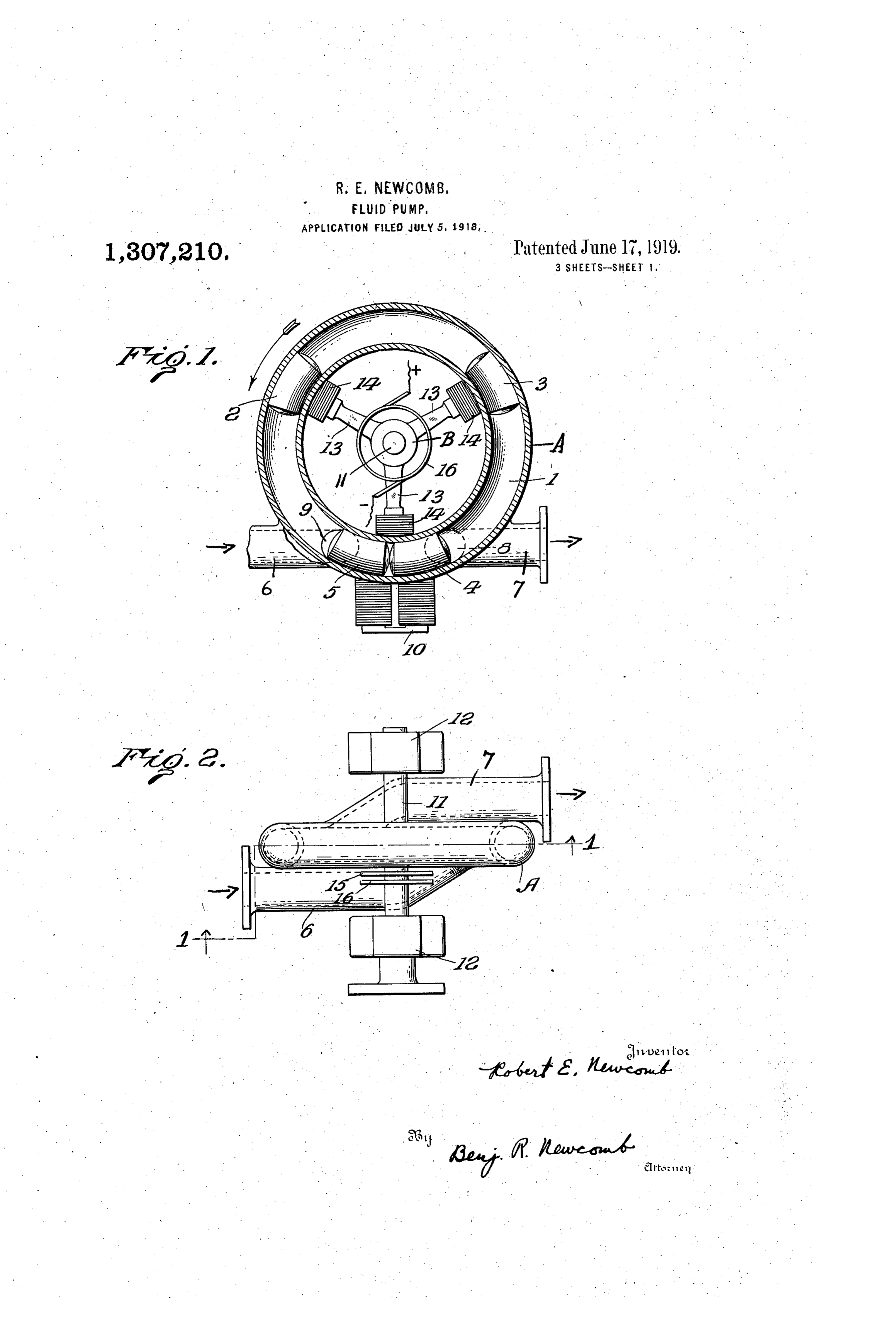
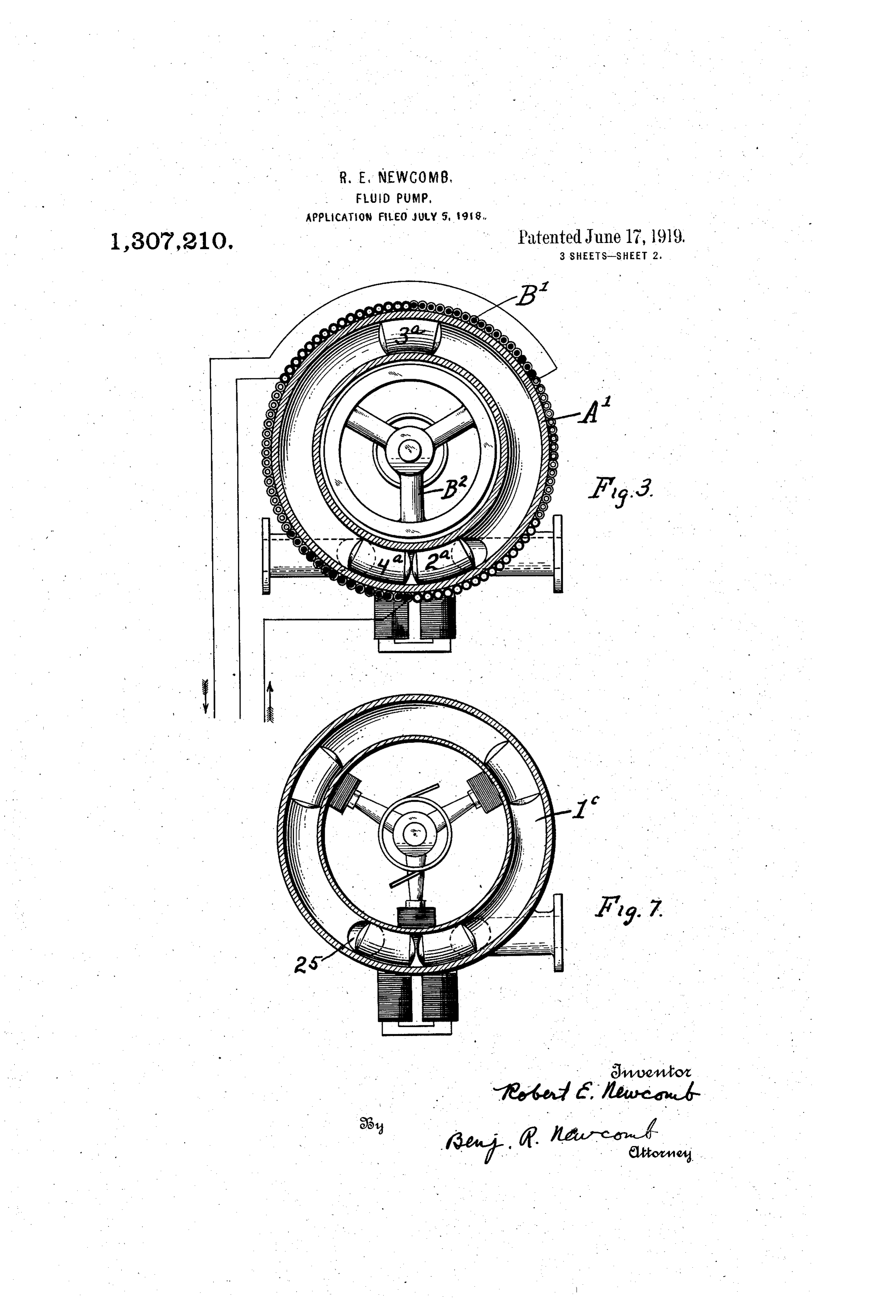
To all whom it may concern. structed for use with an induced rotating 55 . Be it known that I, Robe:RT E. NEwcoMB, tion a citizen of the United States, residing at field motor of the class which occurs in an induc
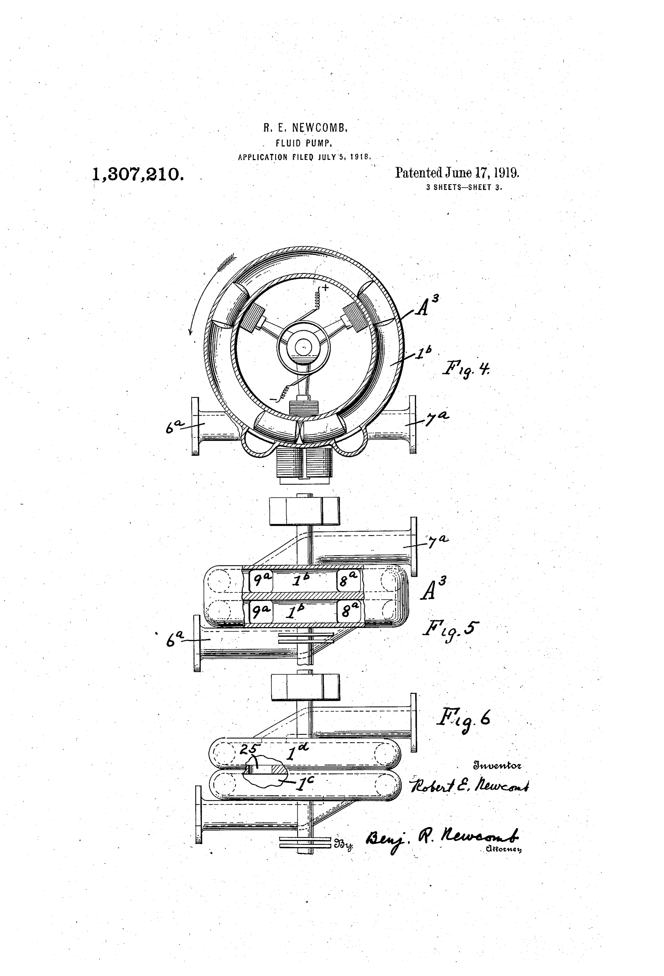
Holyoke, in the county of Hampden and Fig. 4 is a vertical sectional view of a State of Massachusetts, have invented cer pump having a plurality of chambers ar 60 tain new and useful Improvements in Fluid ranged side by side and having common Pumps, of which the following is a specifi Suction and discharge pipes.
cation. N . .. Fig. 5 is a top plan view thereof, partly My invention relates to fluid pumps and in section.
0. more especially to that class of pumps Fig. 6 is a top plan view partly in section wherein pistons are employed which are of the pump having a plurality of chambers 65 moved by means other than mechanical con charge arranged side by side and in which the dis nections, port of one chamber is also the suc I am aware that it is generally old to tion port of the next adjacent chamber. 5 move the pistons of a pump rectilinearly by Fig. 7 is a vertical sectional view of the 70 the use of a magnetic field but I propose pump shown in Fig. 6.
to utilize magnetic influence to move the In detail:
pistons of a pump in a continuous or endless . In the embodiment of the invention illus orbit, thus providing a pump which gives a trated in Figs. 1 and 2, the pump comprises 20 uni-directional flow having a continuous. a pump casing Ahaving a chamber 1 which non-pulsating influx to the suction and like is in the form of a substantially circular or 75 wise a continuous non-pulsating efflux to the endless orbit in which a plurality of pistons discharge, thereby insuring all of the ad 2, 3, 4 and 5 move by means to be herein vantages of the usual rotary and centrifugal after described. The pump chamber 1 has 25 pumps without the disadvantages of com an inlet pipe 6 and an outlet pipe-7, the in plex construction and, furthermore, giving teriors of which communicate with the cham 80 much better efficiency than that of any cen ber 1, through ports 8 and 9. trifugal pump Rotating concentrically with the orbit of An object of the pump constructed accord movement of the pistons is a rotor B driven 30 ing to the present invention is to move the by any suitable prime mover and carried on pistons by the magnetic influence of a ro a shaft 11 journaled in bearings 12. The 85 tating magnetic field either of the usual ro rotor B is provided with arms 13 carrying tating type or of the induced type such as at their outer ends the magnets 14 energized occurs in a polyphase induction motor. by current supplied thereto by slip rings his 35 In the type of pump here illustrated, pis and 16 from any extraneous source. w tons are confined for movement in one or 9, Between the inlet and outlet ports 8 and 90 respectively, is a stationary magnet 10 more circular or endless pump chambers, and an electrical magnetic field is employed in which acts to momentarily retard the move connection with the pump chambers for mov ment of each piston during passage between 40 ing the pistons in a continuous path around the two ports and until the adjacent pre 95 the same. The chamber or chambers is or ceding piston has advanced sufficiently to are provided with inlet and outlet ports for create a vacuum between the two pistons as, the fluid pumped and between the ports of for instance, in the drawing, the piston 4 has each chamber is located a device for retard been retarded while the piston 3 is now mov
ing the movement passage between theofports, each soE. its ing that a vacuum at its usual rate away from the inlet port 8; thus a vacuum is created between the OO .
will be created between the piston so re two pistons 3 and 4 which draws the fluid tarded and the adjacent preceding piston, in through the inlet port 8 and, at the same thus drawing the fluid into the chamber. time, the piston 5 moving at its usual rate. 50. In the drawings; has displaced through the outlet port 9 that Figure 1 is a vertical section through the bulk of fluid which has been previously 105 pump taken on life 1-1 of Fig. 2. drawn, in between pistons 4 and 5, and as Fig. 2 is a top plan view. the piston 2 continues it engages the piston 5 Fig. 3 is a view showing the pump con and thus forces the piston 5 out of range of
Page 5
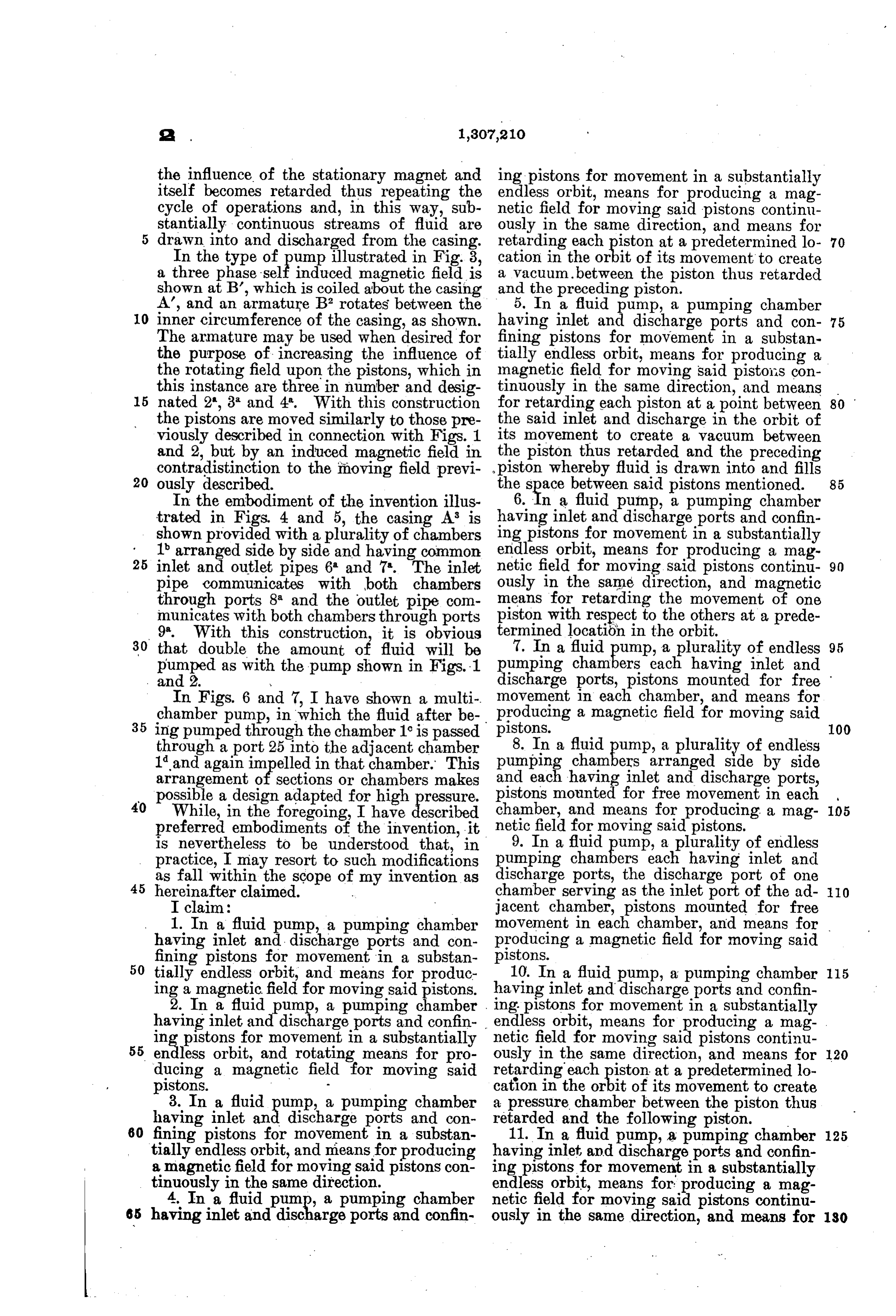
the influence of the stationary magnet and ing pistons for movement in a substantially itself becomes retarded thus repeating the endless orbit, means for producing a mag cycle of operations and, in this way, sub netic field for moving said pistons continu stantially continuous streams of fluid are ously in the same direction, and means for 5 drawn into and discharged from the casing. retarding each piston at a predetermined lo 70 In the type of pump illustrated in Fig. 3, cation in the orbit of its movement to create a three EF induced magnetic field is a vacuum. between the piston thus retarded shown at B', which is coiled about the casing and the preceding piston. A', and an armature B° rotates between the 5. In a fluid pump, a pumping chamber 10 inner circumference of the casing, as shown. having inlet and discharge ports and con 75 The armature may be used when desired for fining pistons for movement in a substan the purpose of increasing the influence of tially endless orbit, means for producing a the rotating field upon the pistons, which in magnetic field for moving said pistos con this instance are three in number and desig tinuously in the same direction, and means 5 nated 2*, 3 and 4. With this construction for retarding each piston at a point between 80 the pistons are moved similarly to those pre the said inlet and discharge in the orbit of viously described in connection with Figs. 1 its movement to create a vacuum between and 2, but by an induced magnetic field in the piston thus retarded and the preceding contradistinction 20 ously described.
to the moving field previ piston whereby fluid is drawn into and fills the sa between said pistons mentioned. 85
In the embodiment of the invention illus 6. In a fluid pump, a pumping chamber trated in Figs, 4 and 5, the casing A is having inlet and discharge ports and confin shown provided with a plurality of chambers ing pistons for movement in a substantially 1 arranged side by side and having common endless orbit, means for producing a mag 25 inlet and outlet pipes 6 and 7. The inlet netic field for moving said pistons continu 90 pipe communicates with both chambers ously in the same direction, and magnetic through ports 8 and the outlet pipe com means for retarding the movement of one municates with both chambers through ports piston with respect to the others at a prede 9. With this construction, it is obvious termined location in the orbit. 30 that double the amount of fluid will be 7. In a fluid EP a plurality of endless 95 pumping chambers each having inlet and
Eged as withY. the pump shown in Figs. 1 discharge and 2. ports, pistons mounted for free movement in each chamber, and means for
In Figs. 6 and 7, I have shown a multi producing chamber pump, in which the fluid after be-, a magnetic field for moving said 35 ing pumped through the chamber 1 is passed pistons. 100 through a port 25 into the adjacent chamber 8. In a fluid pump, a plurality of endless 1 and again impelled in that chamber. This pumping E. arranged side by side arrangement of sections or chambers makes and each having inlet and discharge ports, possible a design adapted for high pressure. pistons mounted for free movement in each , 40 While, in the foregoing, I have described netic chamber, and means for producing a mag- 105 field for moving said pistons.
preferred embodiments of the invention, it is nevertheless to be understood that, in 9. In a fluid pump, a plurality of endless practice, I may resort to such modifications pumping E.E. each having inlet and as fall within the scope of my invention as discharge ports, the discharge port of one 45 hereinafter claimed. chamber serving as the inlet port of the ad- 110 I claim: jacent chamber, pistons mounted for free 1. In a fluid pump, a pumping chamber movement in each chamber, and means for having inlet and discharge ports and con producing a magnetic field for moving said fining pistons for movement in a substan pistons.
50 tially endless orbit, and means for produc 10. In a fluid pump, a pumping chamber 115 ing a magnetic field for moving said pistons. having inlet and discharge ports and confin 2. In a fluid pump, a pumping chamber ing pistons for movement in a substantially having inlet and discharge ports and confin endless orbit, means for producing a mag ing pistons for movement in a substantially netic field for moving said pistons continu 55 endless orbit, and rotating means for pro ously in the same direction, and means for 120 ducing a magnetic field for moving said retarding each piston at a predetermined lo pistons. cation in the . of its movement to create 3. In a fluid pump, a pumping chamber a pressure chamber between the piston thus having inlet Ani discharge ports and con retarded and the following piston. 60 fining pistons for movement in a substan 11. In a fluid pump, a pumping chamber 125 tially endless orbit, and means for producing having inlet and discharge ports and confin a magnetic field for moving said pistons con ing pistons for movement in a substantially tinuously in the same direction. endless orbit, means for producing a mag 4. In a fluid pump, a pumping chamber netic field for moving said pistons continu 65 having inlet and discharge ports and confin ously in the same direction, and means for 130
Page 6
retarding each piston at a predetermined lo- my hand in the presence of two subscribing cation RS,O aretarded pressure chamberofbetween its Yies the to thus piston site witnesses.
and the following piston, and to ROBERTE. NEW COMB. 5 create a vacuum between the retarded pis- ... Witnesses: ton and the preceding piston. CALVIN H. CROUCH, In testimony whereof I have hereunto set WILBUR. K. SEACY.
Provenance
- Collection
- Cited prior art
- Original PDF
- patentimages.storage.googleapis.com →
- Pages
- 6
- Method
- pdftotext (the PDF's own text layer) + pdftoppm 300dpi page scans
- Source
- Google Patents bibliographic record
- Granted
- 1919-06-17
- Transcribed from
- patentimages.storage.googleapis.com →