patent · US4473452
Electrophoresis using alternating transverse electric fields
25 September 1984
Page 1 — bibliographic record
United States Patent (19) 11 Patent Nuraber: 4,473,452 Cantor et al. 45) Date of Patent: Sep. 25, 1984 54 ELECTROPHORESIS USING Attorney, Agent, or Firm-John P. White; Ivan S. ALTERNATENG TRANSWERSE EECTRIC Kavrukov
FIELDS
75) Inventors: Charles R. Cantor; David C.
Schwartz, both of New York, N.Y. Disclosed are an apparatus for and a method of electro 73) Assignee: The Trustees of Columbia University phoretically separating particles by electric fields which are transverse to each other, which alternate between in the City of New York, New York, respective high and low intensities out of phase with
each other at a frequency related to the mass of the (21) Appl. No.: 442,580 particles and which move the particles in an overall 22 Filed: Nov. 18, 1982 direction transverse to the respective directions of the fields. For separating large macromolecules, at least one 51) Int. Cl. ...................... G01N 27/26; G01N 27/28 of the fields preferably has an intensity gradient in a 52) U.S. Cl. ........................... 204/180 G; 204/180 R; direction transverse to its own. The new arrangement 204/299 R makes it possible to: (1) separate particles. (molecules) 58 Field of Search ............ 204/180 G, 299 R, 180 R larger in size than those able to be separated with previ (56) References Cited ously known techniques, (2) carry out separation at
higher speed and at better resolution than is possible with previously known techniques, and (3) concur 4,148,703 4/1979 Trop et al. ...................... 204/299 R rently separate particles which differ greatly in mass Primary Examiner-John F. Niebling (molecular weight).
Assistant Examiner-B. J. Boggs, Jr. 26 Claims, 14 Drawing Figures
GEL
YiSERT
Page 2
Drawing sheet — no readable text.
Page 3
Drawing sheet — no readable text.
Page 4
Fig. S.
o o e d O o O o
o o o ELE e o O E. O
o o o O. O. o O C
DNA COIL
INTO MATRX
SNAke ex o O O E' SHUT O.. o O O. O.
RANDOM E. E." DISTORTED DNA El RE-ALGNMENT
COMPLETED ALGNMENT,
NEW SNAKE FORMED
G. O. O O. O. O O. O.
Page 5
Drawing sheet — no readable text.
Page 6
ELECTROPHORESS USNG ALTERNATING
course is not a highly sensitive basis for obtaining sepa
TRANSWERSEELECTRIC FELDS
rations. Additionally, in known prior art gel electropho resis, different gel concentrations are typically used for
BACKGROUND AND SUMMARY OF THE different mass or molecular weight ranges, thereby INVENTION limiting the range of particles which can be concur This invention was made with government support rently resolved. Furthermore, previously known elec trophoresis techniques are typically used to separate under Contract No. GM14825 awarded by the National only small amounts of particles, and the process cannot Institutes of Health of the United States Department of conveniently be extended to larger amounts. Health and Welfare. The government has certain rights 10 Despite the fact that electrophoresis has been used for in this invention.
some time, and despite the fact that important limita
The invention is in the field of electrophoresis. It is of tions particular interest in terms of its applications in genetic been thereof long and the need to overcome them have also known, no previous proposals are known engineering and molecular biology. which have successfully overcome such limitations. The invention which is based upon the discovery of a 15 new kind of electrophoresis makes it possible, inter alia, This invention is a significant departure from the to carry out important analyses which were not possible established principles of electrophoresis and is based on or practical with previously known techniques. Poten the surprising discovery that electrophoresis through tial applications include the separation of chromosomal deliberately varied electric fields, rather than through DNA, chromosomal mapping, the convenient produc- 20 the uniform fields sought in previously known electro tion of genetic libraries, studies on the effects of various phoresis methods, unexpectedly yields highly desirable drugs on chromosomal DNA, and the convenient char results. More specifically, the invention is based on the acterization of polymers. The invention makes it possi discovery that desirable separation results when parti ble to separate with a high degree of resolution and at cles are subjected to respective electrical fields which high speeds larger particles (molecules) than those ca- 25 move them in overall directions generally transverse to pable of resolution with prior art techniques, to concur the respective general directions of the fields. Particu rently separate particles which differ substantially in larly desirable results are achieved in at least those cases mass. In a preferred embodiment the invention makes it examined to date when at least one of the electric fields possible to lyse cells for electrophoretic separation of has a deliberate intensity gradient in a direction trans macromolecules contained in the cells with minimal 30 verse to its own. As a specific nonlimiting example, two. degradation or breakage. fields can be used which alternate between respective Electrophoresis in which particles such as a mixture high and low intensities out of phase with each other of macromolecules are moved, e.g., through a gel ma and are in directions transverse to each other. For ex trix, by an electric field, is a widely used technique for ample, one of the fields can be on while the other one is qualitative analysis and for separation, recovery and 35 etc. Particularly good results are obtained when the purification. It is particularly important in the study of off, on and off times of the fields are related to the mass of proteins, nucleic acids and chromosomes. See, e.g., the particles to be separated, e.g., when the on and off Cantor, C. R. et al., Biophysical Chemistry, Freeman, periods are proportional to the mass of the particles 1980, Part 2, pp. 676, 683. Indeed, it is probably the raised to a power of about 1.5.
principal analysis.
tool used in most DNA and chromosomal 4 One of the important advantages of this discovery is Difficulties arise when electrophoretic separation of thatwhich it dramatically extends the mass range of particles can be electrophoretically separated at high reso very large particles is attempted. For example, using previously known techniques, the size of the largest lution. As a nonlimiting example, the new technique can DNA molecule routinely handled is that of a bacterio 45 separate at high resolution particles whose mass is about phage (3.2x 10⁷ daltons). Such a limit on size prevents 1.2x 10⁹ daltons, while the upper limit of previously many kinds of desirable analyses from being carried out, known methods which provide lower resolution, is For example, intact chromosomal DNAs are larger and believed to be about 0.5X 10⁹ daltons. It is believed that are typically reduced in size in order to make it possible the new technique can also resolve particles larger than to work with them. This, however, destroys important 50 1.2X 10⁹ daltons, Another important advantage is that information encoded within the DNA and precludes in the new technique resolution is much less dependent many important experiments. on electric field intensity; consequently, the new kind of It has been proposed to extend gel electrophoresis to electrophoresis can be run at much higher speed, so particles of higher mass by reducing the gel concentra long as heat produced can be effectively dissipated. As tions. However, this adversely affects resolution, makes 55 a result, a typical laboratory run can be carried out in 4 experimental conditions difficult to control and has not to 8 hours, while corresponding runs using prior art been successfully applied to DNA molecules having techniques require 12 to 100 hours. Another significant molecular weights greater than about 5X 10⁸ daltons, advantage of the new technique is that larger amounts Fangman, W. L., Nucleic Acids Research, Vol. 5, No. 3, of sample, as compared to the known prior art, can be March 1978, pp. 653-655; Serwer, P., et al., Electropho 60 used, thus giving increased resolution and sensitivity. A resis, 1981, Walter, deGreuyter and Coe, pp. 237-243, further advantage is that the new technique can simulta It is believed that resolution in previously known neously resolve, in the same gel, particles from a wider electrophoresis techniques is field-dependent since mass range than is believed possible with prior art tech lower electric field intensities generally give higher niques. As a nonlimiting example, the new technique resolution. As a consequence, electrophoresis runs in 65 can resolve simultaneously, in the same gel, particles which higher resolution is desired often take as long as ranging in mass from about 106 to about 109 daltons. 100 hours. Moreover, particle mobility, and hence reso With previously known techniques several different gel lution capability, is believed to vary with the logarithm concentrations would have been required to resolve of the mass of the particles to be separated, which of particles in the narrower mass range from about 106 to
Page 7
about 108 daltons. As yet another important aspect of one of its two pairs of outputs to the d-c power from the invention, a technique has been found to minimize supply 16. One output pair of relay 18 (consisting of a handling damage to cell-derived macromolecules by negative and a positive output terminal) is connected to lysing cells or spheroplasts in a block of gel which is the the top and bottom rows of electrodes 4 (as seen in same as, or compatible with, the electrophoresis gel, FIG. 3), through a respective diode for each electrode. and implanting the entire block in the electrophoresis However, it is only when a switch 22 is closed that all chamber. the electrodes of the top row are connected to the nega These and other advantages of the invention, as well tive output terminal of relay 18; when switch 22 is open, as additional inventive features, will become apparent only the rightmost electrode 14 is so connected. The from the detailed description which follows. 10 other pair of relay 18 output terminals is similarly con BRIEF DESCRIPTION OF THE DRAWINGS nected to the left and right rows of electrodes 14, using a similar switch 24 for the corresponding purpose. Vari
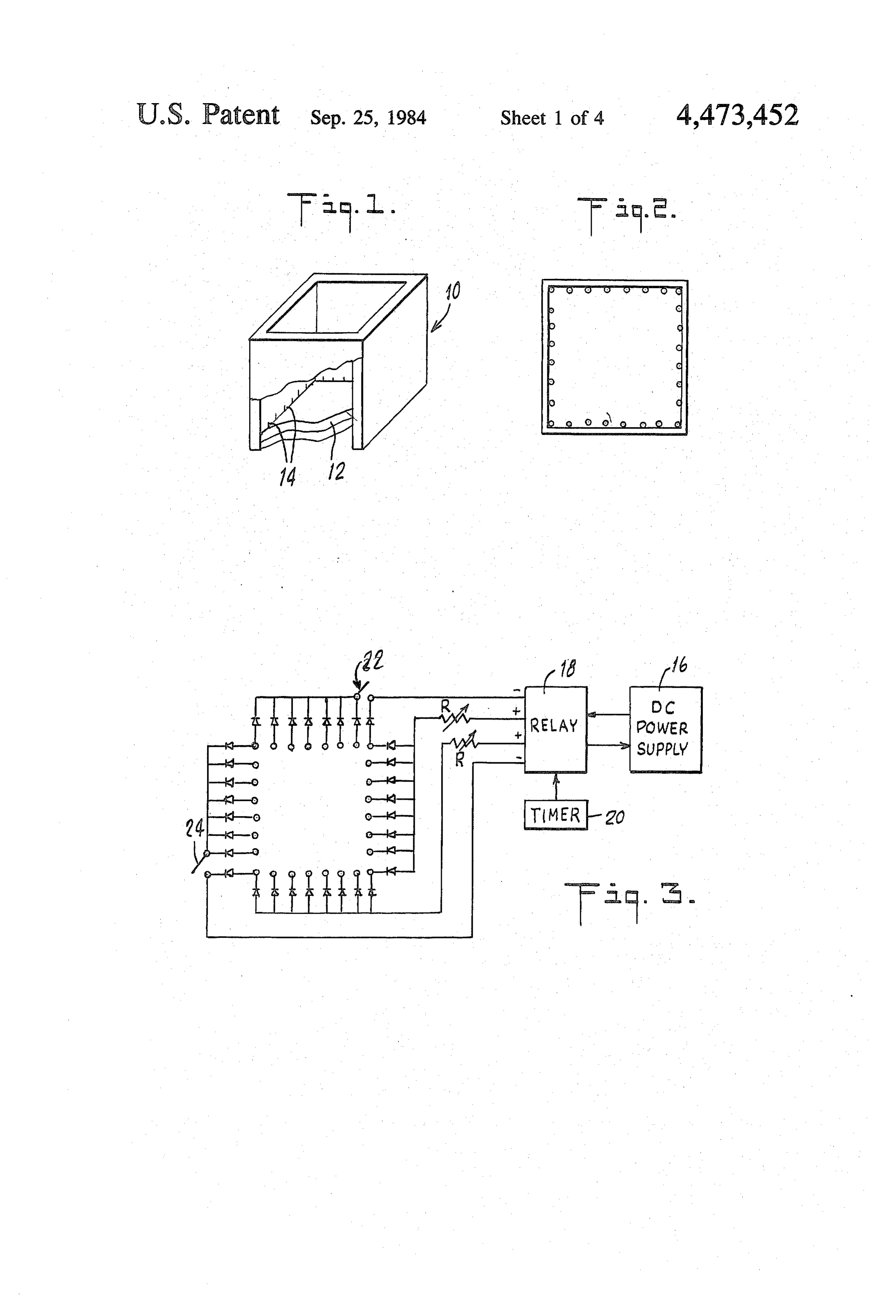
FIG. 1 is a perspective, partly cut-away view of an able resistors R can be used to vary the relevant volt electrophoresis chamber useful in explaining certain ages, as can the controls of power supply 16. The con principles of the invention. 15 trols of timer 20 determine when a particular pair of FIG. 2 is a top plan view of the same chamber. relay 18 terminals is energized and when it is de-ener FIG. 3 is a partly schematic and partly block diagram gized.
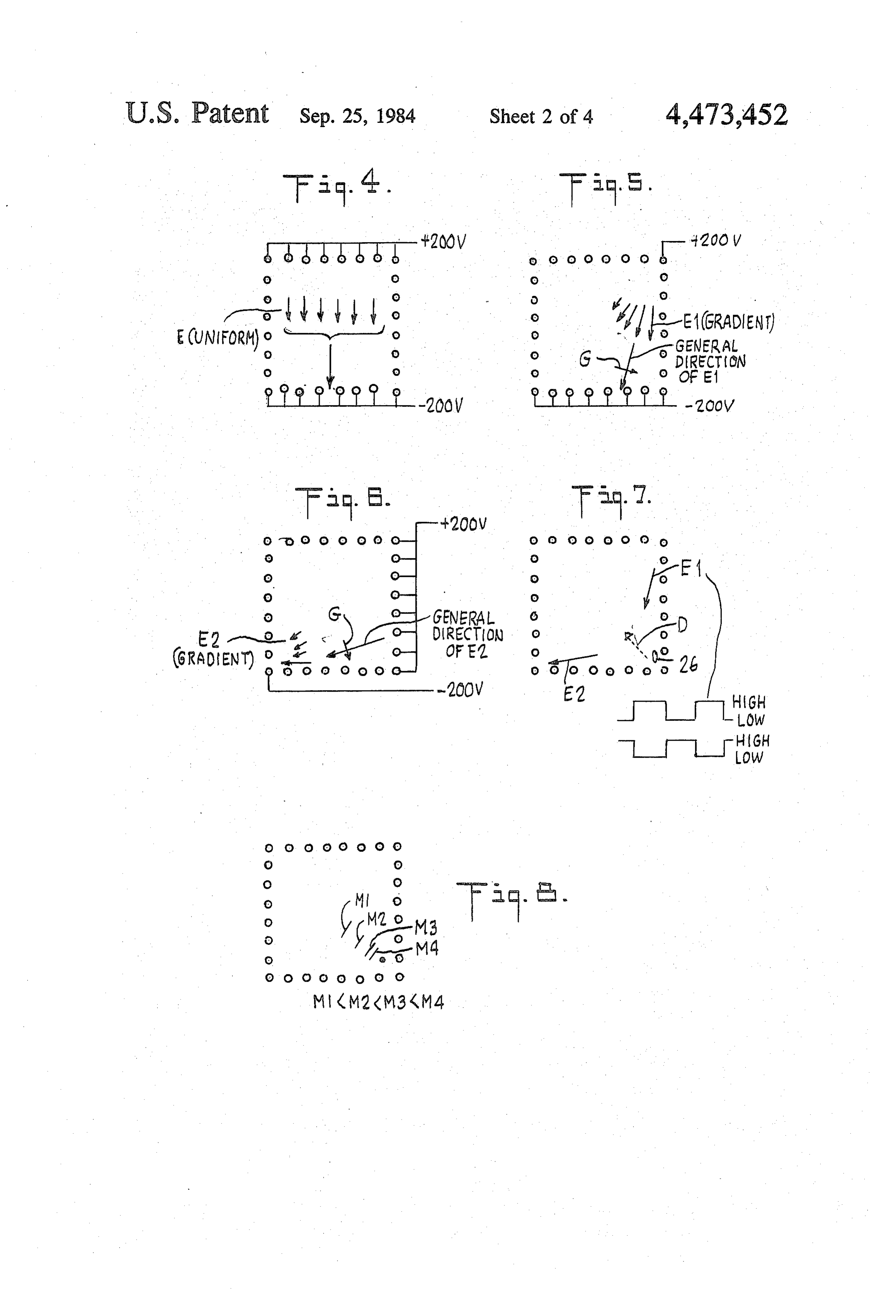
showing an interconnection of exemplary chamber When switch 22 is closed and the relay outputs ener electrodes. gizing the top and bottom rows of electrodes 14 are on, FIGS. 4-7 illustrate exemplary electric fields acting e.g., at +200 and -200 volts respectively, a substan in the electrophoresis chamber. tially uniform electrical field E is established across the FIG. 8 illustrates the movement of particles in the bottom of the electrophoresis chamber, as illustrated new kind of electrophoresis. schematically in FIG. 4. The short arrows in FIG. 4 are FIG. 9 illustrates a hypothesized distortion and uniform in length, to indicate the substantial uniformity movement of a large DNA molecule through agarose 25 of the field, and the longer arrow indicates the general gel under the influence of transverse electric fields act direction of the field (from positive to negative elec ing out of phase. trodes).
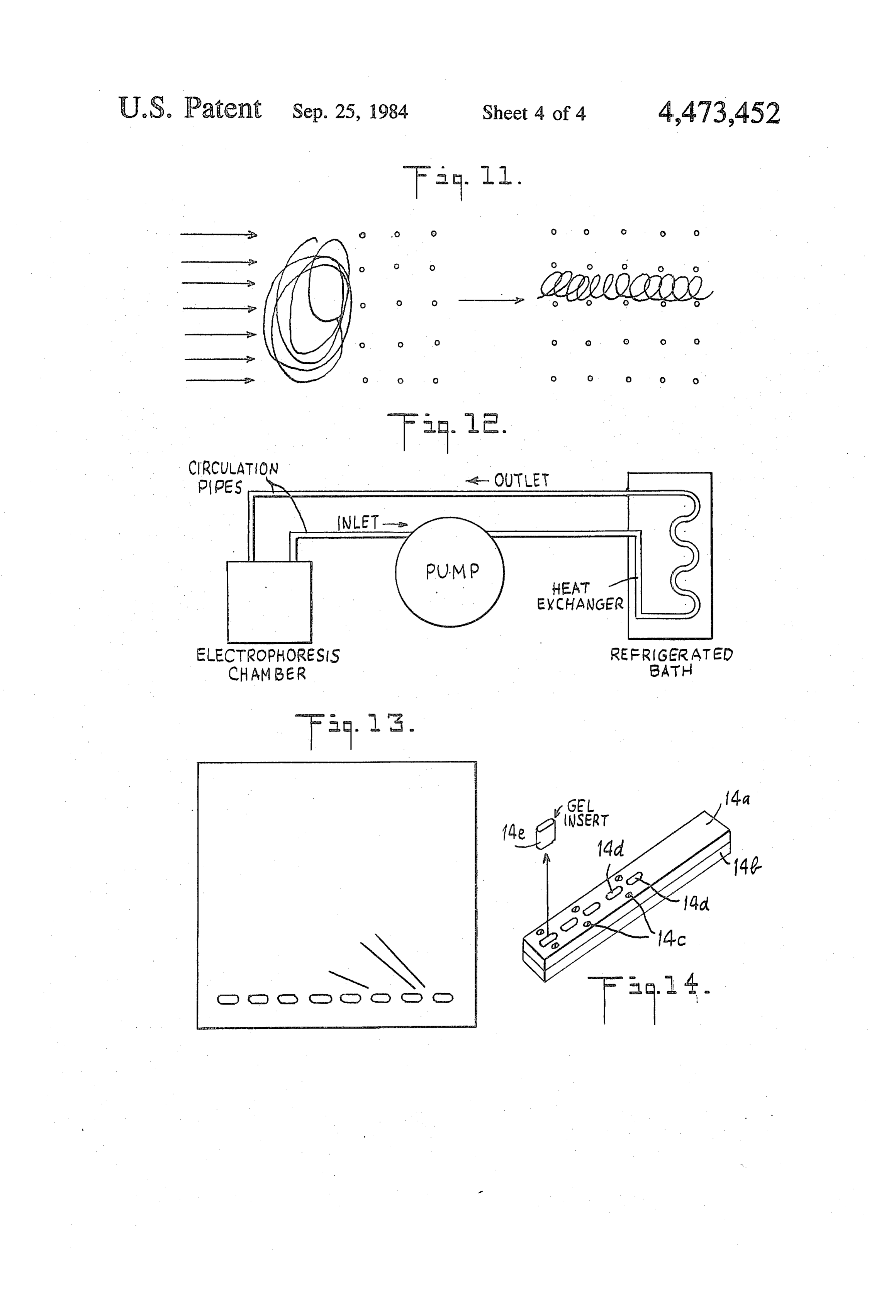
FIG. 10 illustrates the hypothesized effect of a uni While in reality the field is not perfectly uniform in form electric field on a large DNA molecule in agarose intensity throughout the gel, because of the physical gel. 30 arrangement of individual, spaced-apart electrodes, and FIG. 11 is similar to FIG. 10 but illustrates the hy for other reasons, and while the general direction may pothesized effect of an electric field which has a sub deviate somewhat from the vertical (as seen in FIG. 4), stantial intensity gradient in a direction transverse to the for the purposes of this specification such fields will be field direction. called uniform, and are distinguished from fields which FIG. 12 illustrates the circulation of cooled buffer 35 are deliberately made nonuniform, e.g., by means of through the electrophoresis chamber. causing an operatively significant intensity gradient. in a FIG. 13 illustrates the resolution obtained in an ex direction transverse to the overall field direction. perimental example using the new kind of electrophore A field E1 which is nonuniform, in that it has an SES. operatively significant intensity gradient in a direction FIG. 14 is a perspective view of a mold used for 40 transverse to the general field direction, is illustrated in lysing cells or spheroplasts in situ in gel blocks which FIG. 5, and is obtained, in this example, by opening are later inserted into matching wells in the electropho switch 22 such that only the electrode in the upper resis gel. righthand corner of FIG. 5 remains at the --200 V DETAILED DESCRIPTION OF THE potential, while each of the bottom electrodes is at the 45 –200 V potential. The electric field illustrated in FIG.
INVENTION
5 is somewhat fan-shaped, but still has a general direc
An exemplary laboratory device useful in explaining tion, illustrated by the longer arrow, which can be certain principles of the invention is illustrated in FIG. viewed as the vector sum of the individual fields that 1 in a perspective, partly cut-away view, and in FIG. 2 are due to the respective potential differences between in a top plan view. It comprises an open-top, rectangu 50 the upper right-hand corner electrode and the individ lar electrophoresis chamber 10 made of an electrically ual electrodes of the bottom row. The intensity gradient insulating material, such as ' plexiglass, with dimen of interest is in a direction transverse to the general field sions approximately 4'x4'. It supports on its bottom a direction, as shown by arrow G, and is due to the fact layer of a medium 12, such as the agarose gel commonly the distance between the upper righthand corner elec used in electrophoresis, surrounded by electrodes 14. 55 trode and the electrodes of the bottom row increases The electrodes are thin (0.032") platinum wires which (and the intensity per unit volume or unit area of the extend vertically about " each and are arranged about individual fields hence decreases) as one moves to the 1.5 cm apart as seen in the top plan view of FIG. 2. left along the bottom row, as is indicated by the de As one example, the electrode wires can enter the creasing lengths of the shorter arrows.
chamber through respective holes arranged in a hori 60 Similarly, when switch 24 is open and the relay out zontal row about ' above the interior bottom of the puts connected to the electrode at the lower left corner chamber, with each wire extending down, along a re and the electrodes along the right-hand row are ener spective interior side wall, to the interior bottom of the gized, a similar field E2 is generated, as illustrated in chamber. In order to generate the desired electrical FIG. 6. The only significant difference between the fields, electrodes 14 are interconnected as shown in 65 fields in FIG. 5 and FIG. 6 is that the one in FIG. 6 has FIG. 3. In particular, a d-c power supply 16 (such as a different general direction, which is transverse to that Biorad Model 500) supplies d-c power to relay 18 (such of the field E1 in FIG. 5.
as a DPDT, 115 volta-c relay) which is controlled by a One of the unexpected discoveries which this inven programmable timer 20 (such as a Lindberg Enterprises tion utilizes is that if fields such as E1 and E2 alternate Chrontrol 4-Channel CT Series) to connect a selected out of phase with each other between respective high
Page 8
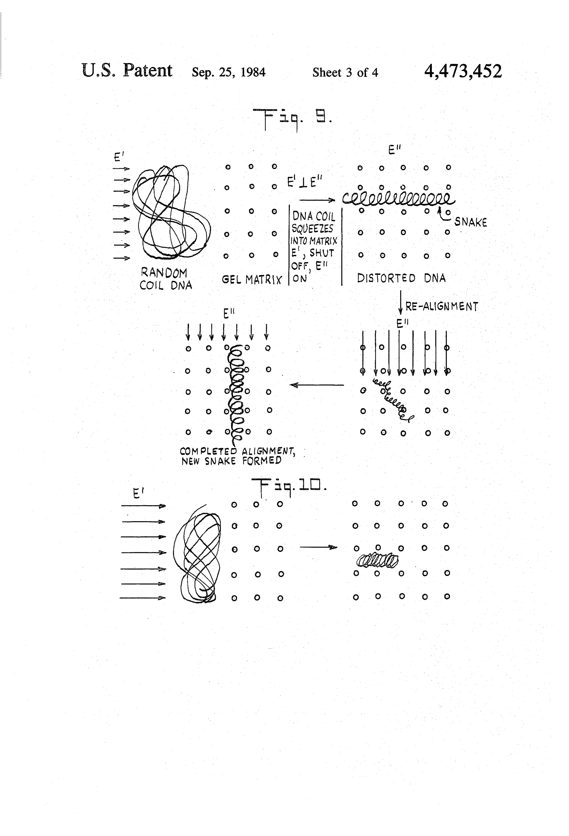
and low intensities at frequencies selected on the basis of one of the critical factors for forcing large molecules, the mass of the particles (e.g., macromolecules) which such as DNA molecules, into the desirable elongated are to be separated electrophoretically, the particles cylindrical or snake shape, as is illustrated in FIG. 11. move from an initial position, such as at 26, in an overall Moreover, it is believed that the proper choice of a direction D which is transverse to both fields E1 and 5 frequency at which the change from one field to an E2, and for any one particle the velocity of movement other should occur, is related to the time it takes the depends on its mass (or charge). As a result, particles of particle (molecule) of interest to orient itself into the different masses (charges) travel different distances desired elongated cylindrical or snake shape, and that from the initial position 26, forming bands such as M1, this time t is related to the mass of the particle (the M2, M3 and M4 in FIG. 8, where lighter particles move 10 molecular weight) M, the effective pore radius of the further distances from the initial position. gel r, and the measured velocity of the particle in the gel It should be noted that the term "transverse' as used v, in accordance with the relationship to M1.5/(r2v). in this specification is not limited to an angle of, or close It should be emphasized that the hypothesis referred to, 90, but includes other substantial angles of intersec to above, while consistent with experimental results to tion. When used with respect to the angle between 15 date, is not to be taken as a factor limiting the scope of electric fields such as E1 and E2, it is meant to exclude the invention, as the invention produces its beneficial only those angles between electric fields in the prior art results despite the fact that the underlying phenomenon which resulted from spurious events or from the inabil may not be well understood, and despite the possibility ity to achieve in practice the design goal of a uniform that a totally different mechanism may be involved. and unidirectional combination of fields. When used 20 The following examples demonstrate certain aspects with respect to the angle between the overall direction of the invention but, of course, should not be taken as of particle movement, the term "transverse' is again limiting its scope:
meant to exclude only angles which resulted from spuri ous events or from the inability of prior art devices to General Electrophoretic Conditions for EXAMPLES have the electrophoretic movement coincide with the 25 A, B and C. desired field direction. The term "operationally signifi cant' intensity gradient means here a gradient which is square Petridishes. Wellswere : Gels about 1 cm thick for cast in 10 cm2 disposable the sample were formed in sufficient to enable the relevant fields to move the rele vant particles in the direction transverse to the general 0.250"x0.0787', spaced 0.125' apart.comb a conventional manner using a plastic with teeth
The gels con field directions, for example, as illustrated in FIG. 7. 30 sisted of 1.5% low endoosmosis agarose (Miles Bio Satisfactory results can be obtained in some cases chemical Company) dissolved in TBE (10.3 g Tris, 5.5 with electric fields which alternate and are transverse to gboric acid and 0.93g disodium EDTA per liter). Elec each other as discussed above, but are substantially trophoresis buffer (TBE) was continuously circulated uniform, as is field E in FIG. 4. However, typically via a magnetically driven polypropylene-housed vane better results are obtained when one of the fields has the 35 pump (Fischer Scientific) and cooled in a re-circulating requisite intensity gradient in the direction transverse to its general direction. Typically, better results are ob refrigerated
bath (Haake, type T-52), as illustrated in intake and discharge ends of the circula tained when both fields have such intensity gradients. tion pipes were close to the gel, and delivered and with While the mechanism by which the new type of elec drew liquid buffer at two diametrically opposite corners trophoresis works is not entirely understood, it is be 40 of the gel square. Samples were loaded into wells using lieved that the application of alternating fields causes a a Gilson Pipetman with the pippette tip ends cut to large particle, such as a coiled DNA molecule, to minimize shear. DNA was visualized after soaking gels squeeze into the agarose matrix by orienting itself first in 0.5 micrograms of ethidium bromide per ml of TBE. along the general direction of one of the fields, then Photographs were taken using Polaroid 107 film with along the general direction of the other, etc. Moreover, 45 shortwave U.V. illumination. Exposure times varied it is believed that using gradient fields (such as E1 and from 15 to 180 seconds at f8 depending on samples. E2) rather than uniform fields (such as E) produces a shearing effect that helps stretch the molecule in the EXAMPLE A: Preparation and Electrophoresis of desired direction. FIG. 9 illustrates this hypothesis by Marker DNA showing a randomly coiled DNA molecule which is 50 Bacteriophage viruses T7, T2, and G were prepared pushed into an agarose gel matrix by a uniform electric by lysing a given amount of virus overnight at 50° C. in field E' and is squeezed into the gel by being formed NDS as described in Laurer et al., Journal of Microbiol into an elongated cylindrical shape (snake). This snake ogy, 1975,95:309-326. The resulting lysates were then is then subjected to a uniform electric field E' and is dialysed overnight against the electrophoresis buffer. gradually distorted away from its initial snake shape 55 The bacteriophage DNA masses in daltons are believed until it forms a new snake, this time oriented along the to be: T7=2.7 x 10⁷; T2=1.2 x 10⁸; and G=5x 10⁸. A general direction of field E", etc., so that its overall 0.02 microgram sample of each DNA was loaded into direction of movement is along the approximate vector the wells in 5 microliters of 10% glycerin, TBE and sum of the directions of fields E' and E'. This initial 0.0015% bromphenol blue. Samples were run into gel hypothesis has been modified, however, by a later belief 60 with a single field for 15 minutes before pulsing. Opti that long chain macromolecules such as DNA probably mal pulse times, in seconds, for resolution of macromol do not snake when their radius of gyration is greater ecules near or at the molecular weight of the following than the effective gel pore radius. Instead, such macro molecules probably condense to a shape more akin to a examples "pulse
time' refers to pulse width, i.e., the time interval "beer can' than a snake, as is illustrated in FIG. 10, and 65 over which one of the fields is on (or high) while the therefore do not move easily in a direction transverse to other one is off (or low). In this experiment fields of the the long axis of the "beer cans.” Indeed, it is believed type and voltage levels illustrated in FIGS. 5 and 6 that the use of a gradient rather than a uniform field is were used, i.e., both fields had intensity gradients. The
Page 9
relative mobility obtained in this experiment was G=1; night, thereby lysing the suspended spheroplasts. Yeast T2=2.5; and T7-8. cells, previously treated with mercaptoethanol were also suspended in 1% agarose gel, but in this case 75
EXAMPLE B: Yeast DNA microliters of a Zymolyase 5000 mixture (2 mg per ml Various strains of yeast were grown to mid-log phase 0.01M sodium phosphate, 50% glycerine) was added to in 100 to 1000 ml of YPD (YPD: 1 g yeast extract, 2 g the inset mixture prior to molding the inserts. 75 micro dextrose and 2 g bactopeptone added to 1 liter of dis liters of Zymolyase was also added to 0.8 ml of LET tilled water). Spheroplasts were made as described in (0.5M tetrasodium EDTA, 0.01M Tris, pH = 7.5). Cryer et al., Progress in Cell Biology, Vol. 12, 1975, pp. Molded inserts with the yeast cells were added to the 39-44. The spheroplasts were then lysed in NDS over 10 LET, and incubated overnight at 37° C. The resulting night at 50° C. Yeast lysates were prepared in NDS with suspended spheroplasts were then lysed in NDS. Both concentrations ranging from about 109 to 2x 10¹⁰ cells cell and spheroplast inserts were placed in matching per ml of lysate. Generally, 90 microliters of lysate were wells in electrophoresis gel. Electrophoresis using the loaded using a blue-tipped (1 ml capacity) Pipetman. conditions discussed above in connection with Exam Samples were run into 1.5% agarose gel at 100 volts for 15 ples A-C, provided good chromosomal DNA resolu 45 minutes with a single field. Pulse times of 15-45 tion.
seconds at 200 volts (fields E1 and E2 of FIGS. 5 and 6) EXAMPLE E: Double Minute DNA gave the molecular weight resolutions shown in re duced scale in FIG. 13. 2.5X10⁷ mouse 3T3-R500 cells were lysed in 0.3 ml 20 of NDS at 50° C. for four (4) days. The lysate were then
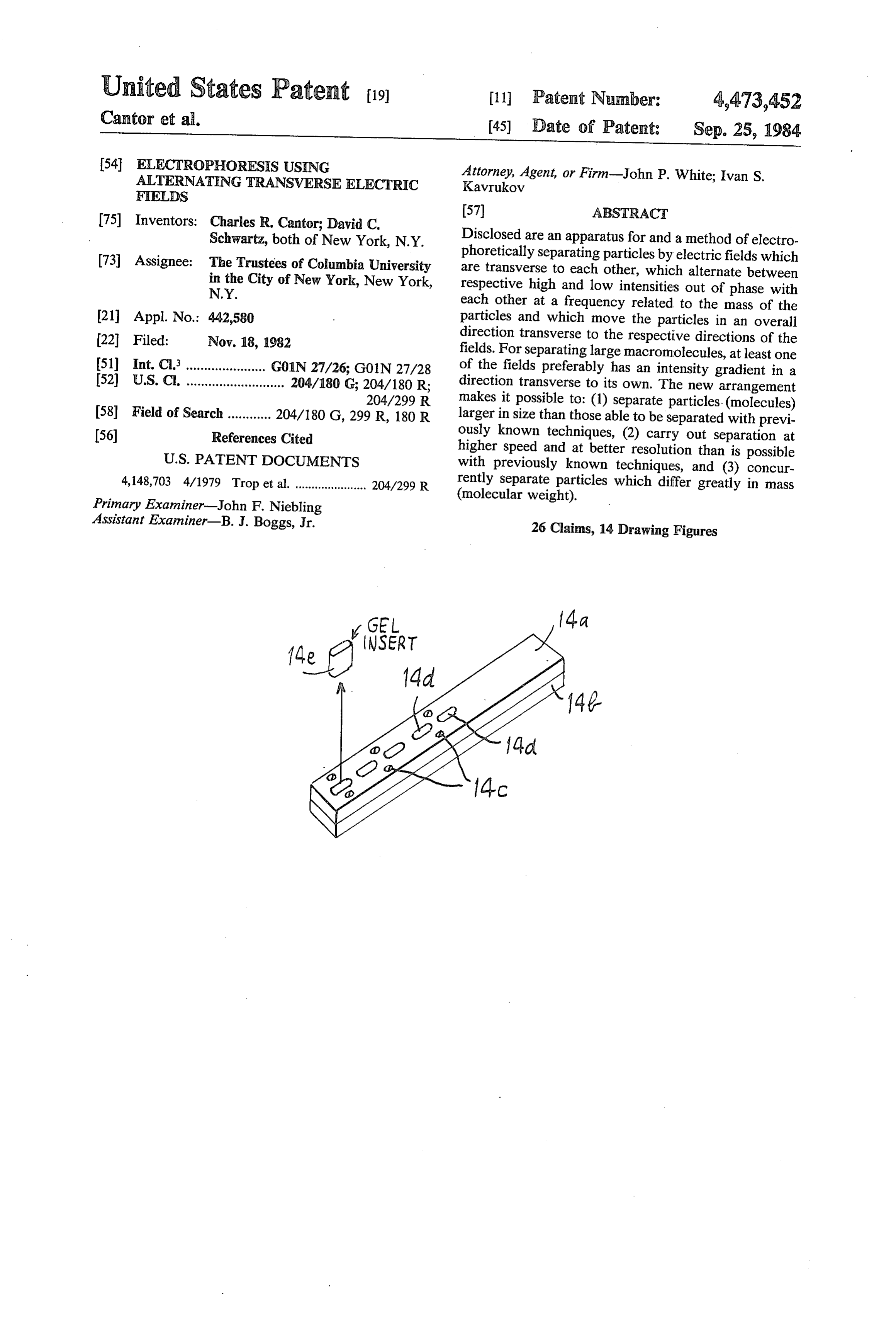
EXAMPLE C: Ethidium Bromide loaded into 1.5% agarose cells in TBE and run at 200 The experimental conditions of Example B were Volts with 30 second pulsing. One diffuse band was used, except that gels were run in the dark and con obtained. It moved as if it had the molecular weight of tained 0.5 micrograms per ml ethidium bromide in the intact double minute DNA (mol. wt. approx. 600x 106). gel as well as the circulation buffer, and pulse times 25 Marker was G phage (mol. wt. approx. 500X 106). were 30 and 45 seconds, using D-273 yeast lysates, The new kind of electrophoresis discussed above has Clear resolution of many chromosomes was obtained. numerous applications. As one example, by use of this In the examples above, lysing was done in a conven technique yeast chromosomal DNA has for the first tional manner and the lysates were transferred to the time been successfully separated and characterized by electrophoresis gel in a conventional manner. It is 30 size. Another use of the new technique is exploring the known that such handling of lysates can result in break nature of DNA-gyrase complexes in E. coli supercoiled, age and other damage to fragile macromolecules. A chromosomal domains to map gyrase locations and thus way has been found, however, to substantially avoid provide tools for eucaryotic chromosome analysis. The such deleterious effects, and it forms a part of this inven new technique is particularly advantageous when dif tion. In particular, in accordance with the invention 35 ferent molecules, such as different DNA molecules, are cells or spheroplasts (cells minus cell walls) can be sus close to each other in mass. The use of alternating fields pended in agarose gel, and this gel can be poured into each with an intensity gradient, tends to sharpen resolu molds to form inserts. The inserts are then placed in tion dramatically and allow unexpected resolution for molecules close to each other in mass. Another use is lysing solution to lyse the suspended cells or sphero plasts, and then the intact inserts are placed snugly into resolving a great number of bands in the same gel, an matching wells in the electrophoresis gel. The gel mak important consideration when eucaryotic DNA is being ing up the inserts can be the same as, or compatible analyzed. Yet another use of the new kind of electro with, the electrophoresis gel. phoresis is to purify molecules such as enzymes, e.g., An illustrative mold used in this new technique is 45 urokinase, myosins or hyaluronic cids so as to provide a shown in a perspective view in FIG. 14, and comprises purified sample which can serve as the basis for devel a pair of matching rectangular blocks 14a and 14b oping a way to produce the same or an equivalent mole which can be secured in the illustrated configuration by cule. As yet another use, the effect of various agents, means of screws 14c. The top block 14a has a number of such as drugs, can be assessed for their effect on chro molding channels 14d which go through the entire mosomes, nucleic acids and proteins because of the thickness of the block, while the bottom block 14b is 50 ability to separate such materials provided by the inven solid. When the blocks are assembled in the configura tion. As yet another example, polymers can be accu tion shown in FIG. 14, suitable agarose gel with sus bution, rately and quickly analyzed for molecular weight distri pended cells or spheroplasts is poured into the molding branching, and other physical properties by use channels 14d and allowed to solidify. The blocks 14a of the new kind of electrophoresis. As still another and 14b are then taken apart, and the insert blocks, such 55 example, intact or cut human, animal or plant chromo as 14e, are carefully extracted, placed in lysing material somes can be analyzed using the new kind of electro under conditions sufficient for staisfactory lysing, and phoresis.
are then carefully inserted snugly into matching wells It should be clear that the laboratory device discussed formed in the electrophoresis gel, e.g., by a comb whose in connection with FIGS. 1-8, and the particular kinds outer shape and dimension matches the molding chan 60 of electric fields used thereby, and the insert molding nels 14d. The following Example D illustrates electro device discussed in connection with FIG. 14, are only phoresis using the new technique. specific examples which are convenient for explaining certain principles of the invention. Numerous variations
EXAMPLE D: Lysing In Gel Inserts are possible and are within the scope of the invention. Yeast spheroplasts (1010 to 1011 cells per ml of 1% 65 For example, a differently shaped electrophoresis low gelling agarose in TBE) were suspended in agarose chamber, or differently produced, distributed or varied gel and poured into the mold channels to form inserts. electric fields can be used so long as the particles are The inserts were then placed into NDC at 50° C. over acted on by electric fields varying with time so as to
Page 10
move then in overall directions generally transverse to of a selected amplitude, such as at a frequency from at least two of the relevant, operationally significant about 106 to about 109 Hz.
fields. For example, the desired fields can be generated What is claimed is:
by differently shaped electrodes, by suitably excited 1. An analytical electrophoresis method of separating coils or by other sources or combinations of different (in particles which is capable of separating at least large kind) sources, and the relevant field directions can be DNA molecules and comprises subjecting said particles controlled by other means, such as without limitation, in a suitable medium to at least two electric fields vary changing the net direction of the field or changing the ing with time and having generally co-planar overall electrode characteristics (e.g., potential). Similarly, the directions which are transverse to each other, to move desired field gradient can be produced in any number of O the particles in an overall direction generally co-planar ways, such as by selecting an appropriate shape for the with but transverse to the respective overall directions relevant electrodes, by maintaining different electrode of said fields to achieve high resolution analytical elec portions at different potentials or by the interaction of trophoresis separation of said particles into a pattern of two or more fields. Moreover, more than two fields can bands.
be used, so long as the net effect is at least to act in the 15 2. A method as in claim 1 in which at least one of the desired manner on a particle first in one direction, then fields has an intensity gradient in a direction transverse in another direction transverse to the first, etc., so as to to and generally co-planar with its overall direction for move the particle in a third direction transverse to the at least a portion of the time it acts on the particles. first two. 3. A method as in claim 1 or 2 in which said at least It has been found desirable, in the above-described 20 two fields vary by alternating between respective low preferred exemplary embodiment of the new electro and high intensities out of phase with each other. phoresis device, to have a number of discrete elec 4. A method as in claim 3 in which the timing of said trodes, and to interconnect them through devices (such alternating is related to the mass of the particles to be as diodes) which allow current flow to each in only a separated.
selected direction. Moreover, it has been found desir 25 5. A method as in claim 1 in which said fields acting able to have the wire electrodes extend along the inte on the particles to cause them to move vary with time as rior sidewalls of the chamber vertically, or nearly so, a function of the mass of the particles raised to the because such electrodes make it particularly convenient power of about 1.5.
to generate the desired electrical fields, and because 6. A method as in claim 1 in which the particles are with such electrodes when they are long enough in the 30 polypeptide molecules.
vertical direction it is possible to have several gel layers 7. A method as in claim 1 in which the particles are on top of each other, each containing samples of parti myosin or hyaluronic acid molecules.
cles, and to subject all of them to substantially identical 8. A method as in claim 1 in which the particles are electric fields so as to carry out electrophoresis in all of nucleic acid molecules.
them concurrently. To generate more complex fields, or 35 9. A method as in claim.8 in which the nucleic acid to provide more freedom of choice in producing fields molecules are DNA molecules.
of selected characteristics, such as the fields E, E1 and 10. A method as in claim 1 in which the particles are E2 in FIGS. 4-6, each electrode (or at least electrode of chromosomes.
a selected plurality of electrodes) can have its own, 11. A method as in claim 10 in which said chromo switchable, power supply connection such that each 40 somes are derived from a eucaryote.
can be selectively maintained at any positive or negative 12. A method as in claim 1 in which the particles are electrical potential within a selected range (or at human chromosomes.
ground). In some cases, as few as three electrodes will 13. A method as in claim 1 in which the particles are suffice, and two of them can be connected (intermit animal chromosomes.
tently) to the same potential, so long as they cooperate 45 14. A method as in claim 1 in which the particles are with each other to produce at least two electrical fields plant chromosomes.
which have the desired characteristics (i.e., being trans 15. A method as in claim 1 in which the particles are verse to each other). yeast chromosomes.
As one variation, the new kind of electrophoresis 16. A method as in claim 1 in which the particles arrangement described above can make use of high 50 move in a gel medium having an effective pore size less frequency switching between transverse fields, e.g., at than the size of the particles.
frequencies in the range from about 106 to about 109Hz, 17. A method as in claim 16 in which the particles superimposed on one or more steady, or more slowly being separated are obtained by lysing whole cells or switching fields such as the fields E, E1 and E2 dis spheroplasts in an insert of the same or a compatible gel cussed above. It is believed that the rapidly switching 55 which is thereafter placed in said gel medium and in field or fields can help rotate (or orient) particles such as which said electrophoretic separation is carried out macromolecules in a desired manner while the steady or without first separating said particles from the lysed slowly switching field or fields can serve to move the whole cells of spheroplasts.
particles in the desired overall direction. This arrange 18. A method as in claim 1 in which said medium is a ment of rapidly switching fields and steady or slowly 60 layer of gel and including the step of suspending whole switching fields can in fact use as few as two transverse cells or spheroplasts in the same or compatible gel mate fields, at least one of them having a steady or slowly rial and solidifying the suspension into a solid insert, switching intensity component and a rapidly switching lysing the cells or spheroplasts without removing them intensity component superimposed thereon. For exam from the solidified gel insert, and thereafter placing the ple, mutually transverse fields E1 and E2 as in FIG. 7 65 lysed insert into a matching well in said layer of gel and can be used, but at least one of the electrodes can have subjecting it to said electric fields, and wherein at least Superimposed on the illustrated squarewave voltage one of said fields has an intensity gradient along the gel waveform, a much higher frequency voltage waveform layer.
Page 11
19. A method as in claim 1 in which said medium has and thereby separate said particles into an analyti a pore size less than the particle size and the action of cal electrophoresis band pattern. said electric field on the particles repeatedly changes 23. Electrophoresis apparatus as in claim 22 in which the molecular configuration of the particles to cause the field generating means comprise at least three dis them to move through said medium. crete electrodes spaced apart from each other and 20. A method as in claim 1 including controlling said means for maintaining the respective electrodes at re field for selective sharpening of a selected part of said spective independently selectable potentials for respec pattern of bands. tive selected time periods.
21. A method of detecting or diagnosing genetic 24. An apparatus for analytical electrophoresis com phenomena correlated with variations in the molecular 10 prising:
weight of chromosomes, nucleic acids or proteins com a support for a layer of medium in which one or more prising separating the chromosomes, nucleic acids or samples of particles can be placed for separation proteins into an analytical electrophoresis band pattern into an analytical electrophoresis band pattern by subjecting them to electric fields which have overall 15 at alongleast the plane of the layer;
three electrodes spaced from each other and directions transverse to and generally co-planar with arranged at selected positions to contact the me each other, at least one of which has a field intensity dium; and gradient transverse to and generally co-planar with its means for maintaining the respective electrodes at overall direction, and wherein the respective intensities respective independently selectable electrical po of the fields are varied over time periods which are out 20 tentials for respective selected time periods to ef of phase as between respective fields and are related to fect said separation of the particles into an analyti the molecular weight of the chromosomes, nucleic acids cal electrophoresis band pattern.
22. An apparatus for analytical electrophoresis com which the electrophoresis
means for apparatus as in claim 24 in maintaining the electrodes at re prising: 25 spective potentials comprise means for causing the elec a support for a medium in which one or more samples trodes to generate at least two electrical fields having a of particles to be separated can be placed; selected characteristic varying out of phase as between means for generating electric fields which act on the the two fields, said fields having overall directions particles along respective different overall direc transverse to each other in the layer plane and causing tions transverse to and generally co-planar with 30 the particles to move in a third overall direction which each other and for causing at least one of the fields is along the layer plane and is transverse to the respec to have an intensity gradient transverse to and tive overall directions of said fields.
generally co-planar with its overall direction; and 26. An apparatus as in claim 25 in which the means means for repetitively varying selected characteris for causing the electrodes to generate said at least two tics of the respective fields over time periods which 35 electric fields comprise diode connections between the are out of phase as between different fields and are at least three electrodes which are switchable to selec related to the mass of the particles to be separated, tively energize selectable combinations or subcombina to move the particles in an overall direction trans tions of electrodes to thereby control the intensity, verse to and generally co-planar with the respec uniformity and/or gradients of said fields. tive overall direction of each of two varying fields 40 ck k ck ck k
Provenance
- Collection
- Cited prior art
- Original PDF
- patentimages.storage.googleapis.com →
- Filed
- 1982-11-18
- Pages
- 11
- Method
- pdftotext (the PDF's own text layer) + pdftoppm 300dpi page scans
- Source
- Google Patents bibliographic record
- Granted
- 1984-09-25
- Inventors
- Charles R. Cantor; David C. Schwartz; Columbia University in the City of New York
- Transcribed from
- patentimages.storage.googleapis.com →