patent · US4730602
Apparatus for automatically directing solar radiation focused by a reflector
15 March 1988
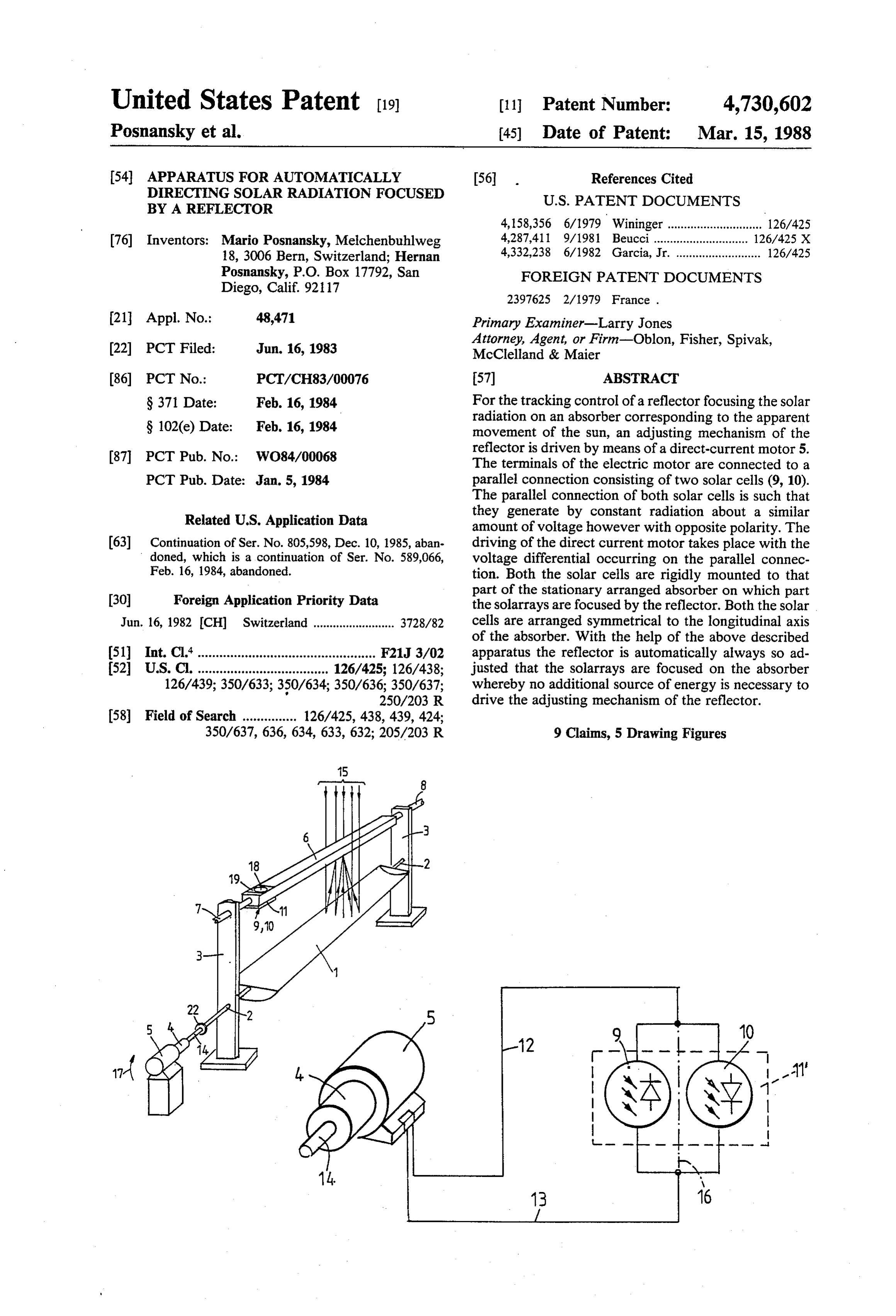
Page 1 — bibliographic record
United States Patent (19) 11 Patent Number: 4,730,602 Posnansky et al. (45) Date of Patent: Mar. 15, 1988 (54) APPARATUS FOR AUTOMATICALLY 56 . References Cited DIRECTING SOLAR RADATION FOCUSED U.S. PATENT DOCUMENTS
BY A REFLECTOR
76 Inventors: Mario Posnansky, Melchenbuhlweg 4,287,411 9/1981 Beucci......... ... 126/425 X 18, 3006 Bern, Switzerland; Hernan 4,332,238 6/1982 Garcia, Jr. .......................... 126/425 Posnansky, P.O. Box 17792, San FOREIGN PATENT DOCUMENTS
Diego, Calif. 92117
21 Appl. No.: 48,471 Primary Examiner-Larry Jones Attorney, Agent, or Firm-Oblon, Fisher, Spivak, (22) PCT Filed: Jun. 16, 1983 McClelland & Maier (86 PCT No.: PCT/CH83/00076 57 ABSTRACT S371 Date: Feb. 16, 1984 For the tracking control of a reflector focusing the solar radiation on an absorber corresponding to the apparent
S 102(e) Date: Feb. 16, 1984 movement of the sun, an adjusting mechanism of the 87 PCT Pub. No.: WO84/00068 reflector is driven by means of a direct-current motor 5. The terminals of the electric motor are connected to a
PCT Pub. Date: Jan. 5, 1984 parallel connection consisting of two solar cells (9, 10). The parallel connection of both solar cells is such that
Related U.S. Application Data they generate by constant radiation about a similar amount of voltage however with opposite polarity. The 63 Continuation of Ser. No. 805,598, Dec. 10, 1985, aban driving of the direct current motor takes place with the doned, which is a continuation of Ser. No. 589,066, voltage differential occurring on the parallel connec Feb. 16, 1984, abandoned. tion. Both the solar cells are rigidly mounted to that 30 Foreign Application Priority Data part of the stationary arranged absorber on which part the solarrays are focused by the reflector. Both the solar
Jun. 16, 1982 CH) Switzerland ......................... 3728/82 cells are arranged symmetrical to the longitudinal axis of the absorber. With the help of the above described (51) Int. Cl."................................................. F21J 3/02 apparatus the reflector is automatically always so ad 52 U.S. C. .................................... 126/425; 126/438: justed that the solarrays are focused on the absorber 126/439; 350/633; 350/634; 350/636; 350/637; whereby no additional source of energy is necessary to p 250/203 R drive the adjusting mechanism of the reflector.
350/637, 636, 634, 633, 632; 205/203 R 9 Claims, 5 Drawing Figures
Page 2
Drawing sheet — no readable text.
Page 3
Drawing sheet — no readable text.
Page 4
cording to the invention in simplified perspective repre
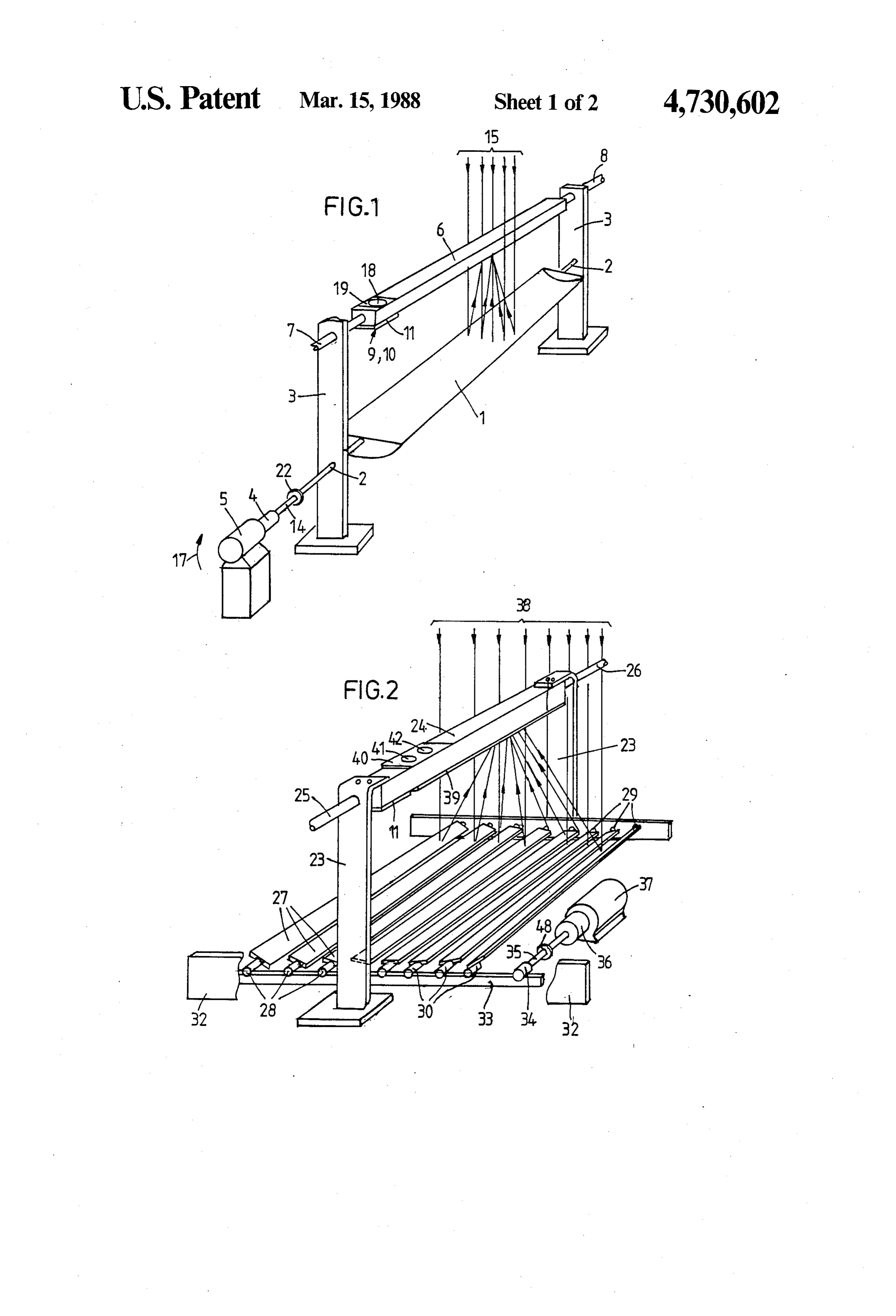
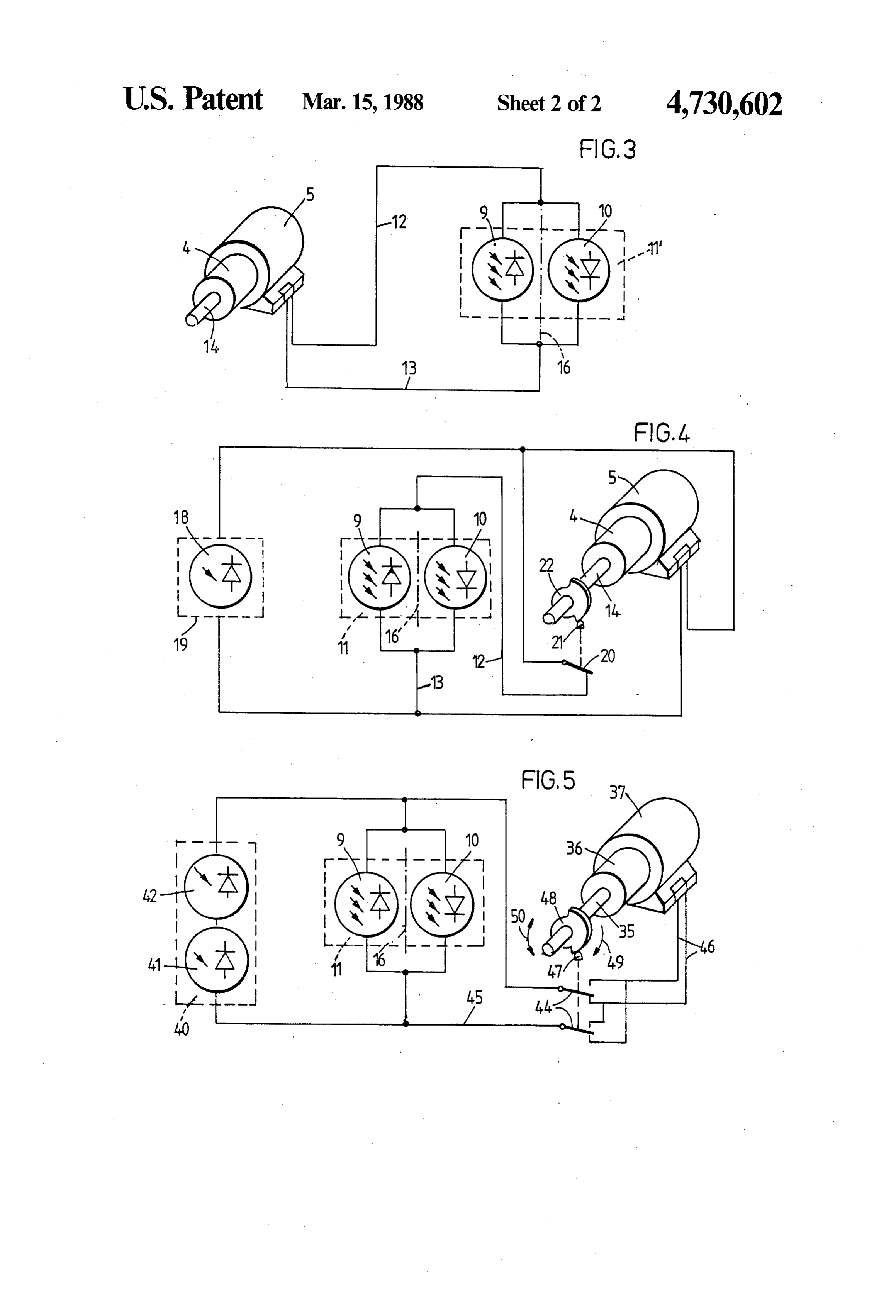
APPARATUS FOR AUTOMATICALLY sentation,
DIRECTING SOLAR RADATION FOCUSED BY A FIG. 3 the elementary circuit diagram of a first sim REFLECTOR ple embodiment of the apparatus according to the in vention,
This application is a continuation of application Ser. FIG. 4 the elementary circuit diagram of a second No. 06/805,598, filed on Dec. 10, 1985, now abandoned, embodiment of the apparatus according to the inven which is a continuation of Ser. No. 06/589,066, filed on tion, and
Feb. 16, 1984, now abandoned. FIG. 5 the elementary circuit diagram of a third em The invention relates to a solar radiation collection 10 bodiment of the apparatus according to the invention. apparatus and more specifically a solar energy plant FIG. 1 shows a solar energy plant having an at least having a reflector which is adjusted to follow the path approximately cylindrical parabolic reflector 1 which is of the sun. rotatable about a swivel axis 2. The swivel axis 2 is In U.S. Pat. No. 3,861,379 a solar collector is de mounted in vertically disposed supports 3 and rotation scribed which possesses for the control of tracking of 15 connected via a reduction gear 4 to an electric motor 5. the sun a photoelectric arrangement which is coupled to In the region of the upper ends of the supports 3 an an adjusting mechanism via an electric motor. A second absorber 6 is rigidly disposed. The absorber 6 is an photoelectric arrangement is present so that in the case elongated container, preferably of a metal. The outer of an overcast sky, the rotation signal emanating from 20 sides of the container are black so that as great a propor the first photoelectric arrangement for the electromag tion as possible of the solar energy striking it is con netic arrangement is interrupted, and in this way a rota verted into heat. Provided for at each of the end faces of tion of the reflectors is avoided. A time switch ener the container 6 is one pipeline 7, 8, respectively, each, gized at the end of the day ensures that the motor causes over which a heat carrier, for example water, is sup the reflectors to return to the morning position. Such a 25 plied to the container and carried off from the con suntracking system is complicated and accordingly tainer, respectively. Because the container forming the expensive. absorber 6 is rigidly disposed, the pipelines can likewise In CH patent specification No. 627,259 a solar collec be rigidly laid.
tor having a solar radiation focusing reflector is de 6 is so distance
The chosen between the reflector 1 and the absorber that the solar energy is concentrated on scribed. Parallel to the axis of rotation of the reflector, the underside of the absorber 6 not along a sharp focal an elongated absorber is disposed for receiving the solar 30 line, radiation focused by the reflector. Sun-tracking means but that an elongated focal spot results, the width reacting to the solar radiation and actuating the adjust of which is less than the width of the underside of the ing mechanism are further provided for keeping the absorber 6.
focusing of the solar radiation on the absorber. The 35 to the inventionembodiment
The simplest comprises, of the apparatus according besides the electric motor 5, sun-tracking means comprise two elongated sensor con two solar cells 9 and 10 which are disposed tainers situated opposite the reflector and, viewed from of the absorber 6 facing the reflector 1, i.e.,atona location the un the reflector reciprocally, extending at least for the derside of the absorber 6, on both sides of the longitudi most part on opposite sides of the absorber. In each of nal center line of the underside. These two solar cells the containers there is a working medium which is, in 40 are not directly visible in FIG. 1 but are only indicated operation, partially in the liquid phase and partially in by the arrow 9, 10. FIG. 3 shows the way in which the the vapor phase, the vapor pressure of which is, two through an evaporation-condensation process, propor motorsolar 5.
cells 9 and 10 are connected to the electric
The two solar cells 9 and 10 can preferably be tional to the amount of solar radiation received from the respective container and from the reflectors. The two 45 cells 9 and 10 support disposed on a 11, in which connection the solar can communicate heat-conductively with working-medium pressures are mutually and oppositely the absorber 6 via the support 11. active upon the adjusting mechanism in such a way that The solar cells 9 and 10 are connected in parallel a pressure differential occurring upon a deviation of the oppositely focusing at the absorber corrects the position of the such a way tothatoneupon another, i.e., they are connected in incident solar radiation they each reflectors for the said deviation. These known sun 50 generate a voltage up to polarities opposite to one an tracking means are simpler in construction than the other. The ones of the terminals of the solar cells 9 and aforementioned sun-tracking means having photoelec 10 connected to one another are connected over a con tric arrangements. On the other hand, however, pres ductor 12 to the one terminal and the other terminals of sure lines and two piston-cylinder drives are needed, the polar cells 9 and 10 are connected over a conductor which parts take up a relatively large space, and the 55 13 to the other terminal of the electric motor 5. installation of these parts is not exactly easy. The electric motor 5 is a direct-current motor having It is the task of the invention to provide an apparatus a low internal resistance so that by means of the voltage of the kind initially mentioned to which the mentioned delivered by the solar cells 9 and 10, it produces a disadvantages do not attach. torque sufficient to swivel the reflector 1. When the The invention is explained in more detail below, by optical axis of the reflector 1 is aligned opposite the sun, way of example, with reference to the drawing. the incidents sunrays, indicated in FIG. 1 by the arrows FIG. 1 shows a solar energy plant having a reflector, 15, are focused on the surface region which corresponds an absorber, and an embodiment of the apparatus ac to the underside of the absorber 6. In this case the same cording to the invention in simplified perspective repre amount of light per unit of time strikes each of the two sentation, 65 solar cells 9 and 10 when they are disposed symmetri FIG. 2 another solar energy plant having a reflector cally with respect to the longitudinal center line of the assembled from strip-shaped reflector elements, an ab underside of the absorber 6 represented by the dot-dash sorber, and another embodiment of the apparatus ac line 16 in FIG. 3. They therefore generate approxi
Page 5
mately equally high voltages, which are opposite to one disposed on a heat-conductive support 19 which is fixed another, however, so that a differential voltage occurs on the top side of the absorber.
at the terminals of the electric motor 5. Through the The further solar cell is, as already mentioned, di apparent movement of the sun relative to FIG. 1, for rectly connected to the terminals of the electric motor. instance toward the right, the focal spot focused on the 5 The conductor 12 of the parallel connection formed of underside of the absorber travels in the direction of the the solar cells 9 and 10 is connected via a switching left-hand edge region of the underside of the absorber 6. means, e.g., switch 20, to the winding of the electric This causes a smaller amount of light per unit of time to motor 5. The switch 20 possesses an actuating part 21 strike the solar cell 10 than strikes the solar cell 9. The which cooperates with a cam 22 mounted rotation-fast solar cell 9 thus generates a larger voltage than the solar 10 on the secondary shaft 14 of the reduction gear 4. The cell 10, The result of the differential voltage occurring switch 20 is not depicted in FIG. 1. is that the electric motor 5 swivels the reflector in the The cam 22 is so formed and mounted on the second direction of the arrow 17. In this way the reflector 1 ary shaft 14 that it holds the switch 20 in the position automatically follows the apparently moving sun, the depicted in FIG. 4 as long as the reflector 1 assumes a focal spot being constantly focused on the underside of 15 position which is between the morning position and the the absorber 6. evening position. The switching flanks of the cam 22 are The above-described simple execution of the appara so formed that shortly before the optical axis of the tus according to the invention functions faultlessly as reflector 1 is directed both in the evening position and long as the focal spot strikes one of the solar cells 9 or in the morning position toward the respective horizon, 10 at least partially. When, for example, cloudiness 20 the switch 20 is opened by the cam 22. Because the solar lasting for a fairly long time occurs during the day, the radiation decreases toward evening, and there is no reflector 1 stands still because both solar cells 9 and 10 longer sufficient or no energy for driving the tracking are not irradiated. If the cloudiness lasts longer, so that control, the electric motor 5, and thus also the reflector upon resumed sunshine the focal spot has travelled 1, stops in the evening position. When the sun shines beyond the solar cell 9, no more differential voltage is 25 anew the next day, the further solar cell 18 is irradiated, delivered to the electric motor 5, and the reflector 1 and the electric motor 5 moves the reflector 1 farther in does not move. A similar situation occurs when the the same direction of rotation as on the day before, the reflector 1 is directed toward the west before or after switch 20 being opened, and the reflector 1 being ro sunset and the next morning the sun rises in the east. tated farther in the same direction until it reaches its With this simple embodiment, it is necessary to adjust 30 morning position. Shortly before, the switch 20 is again the reflector 1 by hand or by other means so far that the closed. After the focal spot has travelled over the solar focal spot strikes one of the two solar cells 9 or 10 at cell 9 to the solar cell 10, the latter generates a counter least partially. voltage to the voltage generated by the solar cell 9 and In order to meet this disadvantage, the support 11 18. When the difference is small or nil, the electric can, for example, be extended on both sides of the longi 35 motor 5, and thus the reflector 1, stands still, or it is tudinal center axis 16 of the underside of the absorber 6, automatically directed toward the sun by the differen as is depicted in dot-dash lines in FIG. 1. On the under tial voltage occurring through the apparent movement side of the extended support 11" are disposed not only of the sun, in such a way that the focal spot is automati the two mentioned solar cells 9 and 10 but also addi cally focused on the underside of the absorber 6. tional non-depicted solar cells, the solar cells disposed If cloudiness occurs during the day, whereby the on the left-hand part, relative to FIG. 1, of the extended electric motor 5 stands still because none of the solar support 11" being connected in parallel to the solar cell cells 9, 10, or 18 delivers a voltage sufficient for operat 9 and the solar cells disposed on the right-hand part of ing the electric motor 5, the reflector 1 also remains in the extended support 11' being connected in parallel to the position assumed shortly before the appearance of the solar cell 10. The length of the support 11" and the 45 the cloudiness. If the cloudiness only lasts a short time, number of additional solar cells are so chosen that the a part of the focal spot will still strike the solar cell 9, focal spot, in every position of the reflector 1 occurring and the electric motor 5 causes the reflector 1 to follow in the normal operating condition of the plant, the focal up the new position of the sun. If, however, the cloudi spot strikes one of the solar cells disposed on the sup ness lasts so long that upon resumed sunshine the focal port 11". 50 spot has already travelled beyond the solar cell 9, then The advantage of this modified execution is that no merely the further solar cell 18 is exposed to the non switching means are needed in the circuit. On the other focused solar radiation. The voltage thereupon gener hand, however, a plurality of relatively expensive solar ated by it causes the electric motor 5 to readjust the cells are necessary for the tracking control alone. reflector 1 until the focal spot again strikes the under A similar effect as with the above-described extended 55 side of the absorber completely.
support 11" and the number of additional solar cells can This embodiment of the apparatus according to the be achieved with the aid of the circuit depicted in FIG. invention can be used only for reflectors which are 4, having merely one further solar cell 18. This circuit is rotatable by more than 360.
described below in more detail with reference to FIG. FIG. 2 shows another embodiment of a solar energy 1. 60 plant with a further embodiment of the apparatus ac The further solar cell 18 is directly connected to the cording to the invention. Rigidly fixed to the upper end terminals of the electric motor 5 and can be rigidly regions of two supports 23 anchored fast in the ground disposed at any location at which it can receive non are the ends of an absorber 24. At one end of the ab focused solar radiation the whole day. Preferably the sorber 24, a boreline 25 for supplying a liquid heat car further solar cell 18 is disposed on the top side of the 65 rier, e.g., water, is disposed, and at the other end of the absorber 6 and heat-conductively connected to the absorber 24 a pipeline 26 for evacuating the heat carrier same so that the further solar cell 18 is cooled by the from the absorber 24 is disposed. The reflector is heat carrier. In advantageous manner the solar cell 18 is formed by a number of strip-shaped reflector elements
Page 6
27 swivellable about their longitudinal axis. Beyond e.g., to a double-pole switch 44. The other terminals of each end-face side of the reflector elements these the solar cells 9, 10 and 41 are connected over a conduc projects one journal 28, 29, respectively, each, one pin tor 45 to the switch 44. The other side of the switch 44 ion 30 each being disposed between the outer end of the is connected over conductor 46 to the terminals of the journals 28 and the associated end-outer end of the electric motor 37. The switch 44 possesses an actuating journals 28 and the associated end-face side. The jour component 47 which cooperates with a cam 48 fixed on nals 29 are mounted in bearings fixed along a straight the secondary shaft 35 of the reduction gear 36. The line in a cross-beam 31, and the journals 28 are mounted switch 44 is not depicted in FIG. 2. in a similar manner in a bearing beam 32 of which, The cam 48 is so formed and fixed on the secondary however, only the two end regions are visible. Each of 10 shaft 35 that the switch 44 is in the position depicted in the pinions 30 meshes with a rack 33 displaceable in its FIG. 5 while the optical axis of the reflector formed of longitudinal direction. A pinion 34 further engages the the reflector elements 27 moves from the morning posi toothing of the rack 33, which pinion is rotation-con tion into the evening position. The switching flanks of nected to a drive shaft 35 of a reduction gear 36. The the can 48 are so disposed that the switch 44 is moved reduction gear 36 is driven by an electric motor 37. 15 into the non-depicted position when the optical axis of The individual, preferably plane, reflecting surface the said reflector reaches the respective horizon. regions of each reflector element 27 form another angle The position shown in FIG. 5 of the cam 48 with with the plane defined by the row arrangement of the respect to the actuating component 47 corresponds to journals 28 and 29. It is thereby achieved that the solar the morning position of the reflector 27. The incident radiation, indicated for example by arrows 38, are re 20 morning sunrays are focused on the solar cells 9 and 10. flected on the underside of the absorber 24. In order With the apparently moving sun, the reflector 27 is that the focal spot always be focused on the underside automatically swivelled step-wise in accordance with of the reflector 24 even with the apparent movement of the differential voltage occurring, so that the sunrays the sun, the reflectors are swivelled by the same angle, are focused during the entire day on the underside of corresponding to the apparent solar movement, by the 25 the absorber 24, thus on the solar cell arrangement on electric motor 37, the pinion 34, the racks 33, and the the support 39. At this time, electrical energy is deliv pinions 30. ered to a load by the solar cell arrangement, and the The absorber 24 is a so-called hybrid absorber which heat carrier is heated.
comprises a container for the flow-through of the heat When towards evening the energy produced in the carrier and a support 39 mounted with a non-depicted 30 solar cells 9 and 10, and 41 and 42, respectively, by the solar cell arrangement. The solar cell arrangement is weaker solar radiation is no longer sufficient to drive heat-conductively connected to the underside of the the electric motor 37, the latter and the reflector ele container of the absorber 24. The further above men ments 27 stand still. During the day, the drive shaft 35 tioned solar cells 9 and 10 of the apparatus according to has rotated in the direction of the arrow 49. The next the invention are furthermore heat-conductively fixed 35 morning, the sunrays strike only the solar cells 41 and to the underside of the absorber 24 via their support 11. 42 because the reflector is still in the evening position. On the top side of the absorber 24, a support 40 with tw When the unfocused radiation incident on the solar cells further solar cells 41 and 42 is disposed. The solar cells 41 and 42 is sufficiently great, the motor 37 turns the 41 and 42 are, contrary to the solar cells 9 and 10 as well secondary shaft 49 first farther in the same direction as as the solar cell arrangement, not exposed two the fo is indicated by the arrow 49, and this so far until the cused solar radiation but rather to the unfocused solar switch 44 is moved by the cam 48 into the position not radiation. depicted in FIG. 5. Through the actuation of the switch In order for this system to operate properly it is nec 44, the polarity of the voltage supplied to the electric essary to choose and arrange the elements so that the motor 37 is changed, and thus the electric motor 37 motor may be driven by the difference in power be 45 rotates further in the opposite direction, see arrow 50. tween the two solar cells. In order to accomplish this, The switch 44 is so formed that it remains in the newly the individual reflector strips are mounted in bearings in assumed position until the other switching flank of the the journals 28 and 29. Since the friction of the bearings cam 48 actuates the actuating component 47. This is the is very low and the mass of the reflector is balanced, case when the electric motor 37 has rotated the drive astonishingly little power is needed to move the reflec 50 shaft 35 by an angle until the reflector elements 27 have tor. Also, since the movement of the sun is very slow reached their morning starting position. After the re the tracking movement of the reflector is likewise very newed actuation of the actuating component 47, the slow and accordingly the motor may be geared down switch 44 is changed back into its position depicted in by a very large factor. As mentioned above, this result FIG. 5, and the polarity of the voltage generated by the can be accomplished using the proper choice of ele 55 solar cells 41 and 42 is again changed, and the electric ments and a proper arrangement of the elements. Thus, motor 37 rotates further again in the original direction by using low friction bearings and a high gearing ratio, in accordance with the arrow 49. The further rotation it is possible to obtain this result. lasts until the incident solar radiation is focused on the In conformity with the wiring diagram according to solar cells 9 and 10.
FIG. 5, the two further solar cells 41 and 42 are con 60 If heavy cloudiness occurs during the day, so that the nected in series, and this series connection is connected electric voltage generated in the solar cells 9 and 10 no in parallel with the parallel connect formed of the solar longer suffices to drive the electric motor 37, the same cells 9 and 10. The series connection of the further solar and thus also all reflector elements 27 stand still. If the cells 41 and 42 is so connected to the parallel-connected sun shines again after a relatively short time, at least a solar cells 9 and 10 that the solar cells 41 and 42 gener 65 part of the focal spot strikes the solar cell, and the volt ate a voltage with the same polarity as the solar cell 9. age generated in it ensures that the electric motor 37 The one terminals of the solar cells 9, 10, and 42 are readjusts the reflector elements 27 so that the focal spot connected over a conductor 43 to a switching means, again strikes the underside of the absorber 24, thus the
Page 7
solar cell arrangement on the support 39. If the cloudi opposit to one another so that upon irradiation of ness continues for a fairly long time, so that upon re said solar cells with focused solar radiation, electri sumed sunshine the focal spot has gotten outside of the cal voltages are produced which counteract one underside of the absorber 24, a voltage is nevertheless another, said parallel connection being connected generated in the further solar cells 41 and 42 which are directly to said electric motor without amplifica irradiated only by unfocused solar radiation, which tion to be the sole supply of power to said electric voltage drives the electric motor 37 in order to rotate notor. w
the secondary shaft 35 in the direction indicated by the 3. A solar power plant, comprising: arrow 49 until the sunrays are again focused on the a stationary solar radiation collector; underside of the absorber 24. In order to guarantee a 10 a reflector mounted on low friction bearings and sure return of the reflector elements 27 from their eve adjustable about a swivel axis for focusing solar ning position into their morning position, another radiation;
switch likewise actuatable by the actuating member 47 an adjusting mechanism for adjusting said reflector to is connected to the switch 44 at the location designated direct the focused solar radiation onto said collec as 51. This switch is closed when the switch 44 is in the 15 tor;
position depicted in FIG. 5 and opened when the switch an electric motor with low internal resistance con 44 is in the position not depicted in the figure. This nected to a reduction gear having a high gear ratio additional switch guarantees that the return movement for driving said adjusting mechansin; and from the evening position into the morning position is at least two solar cells disposed on the side of said not disturbed by the voltage possibly generated in the 20 collector nearest said reflector, said solar cells solar cell 10. The last-described embodiment of the being connected in a parallel circuit opposite to one apparatus according to the invention is especially suited another so that upon irradiation of said solar cells for the tracking control of a reflector which is not rotat with focused solar radiation, electrical voltages are able by a full 180. produced which counteract one another, said par We claim: 25 allel connection being connected directly to said 1. A solar power plant, comprising: electric motor to supply power to said electric a stationary solar radiation collector; notor.
a balanced reflector having a low friction mounting 4. Apparatus according to claim 3 wherein said elec adjustable about a swivel axis for focusing solar tric motor comprises a winding and the winding of the radiation; 30 electric motor is connected via a doublepole switch an adjusting mechanism for adjusting said reflector to means to the said parallel connection, the switch means direct the focused solar radiation onto said collec comprises an actuating member for determining the tor; position of the reflector, and at least one further solar an electric motor having sufficient torque to drive cell to be irradiated by unfocused solar radiation is said adjusting mechanism through a reduction gear 35 connected in parallel to the said parallel connection. having a high gear ratio, and 5. Apparatus according to claim 3 wherein said elec as least two solar cells disposed on said collector, said tric motor comprises a winding and the winding of the solar cells being connected in a parallel circuit electric motor is connected via a switching means to the opposite to one another, said parallel circuit being said parallel connection, the switching means comprises directly connected to said motor so that upon irra 40 an actuating member for determining the position of the diation of said solar cells with focused solar radia reflector, and at least a further solar cell is connected tion electrical voltages are produced which coun directly to the winding of the electric motor. teract one another and which drive said motor 6. A plant according to claim 3, further comprising a without amplification, said produced voltages further solar cell (18) which is disposed at a location so being the sole supply of power to said motor. 45 that unfocused solar radiation impinges on the further 2. A solar power plant, comprising: solar cell.
a stationary solar radiation collector; 7. A plant according to claim 3 characterized in that a balanced reflector adjustably mounted for low fric the further solar cell (18) is disposed on the side of the tion movement about a swivel axis for focusing collector (6) facing the sun when the plant is in opera solar radiation; 50 tion.
an adjusting mechanism for adjusting said reflector to 8. A plant according to claim 6, 7 or 3 wherein the direct the focused solar radiation onto said collec collector is an elongated receptacle (6) for the convey tor; ance therethrough of a liquid heat carrier. an electric motor for driving said adjusting mecha 9. A plant according to claim 8 wherein a solar cell nism having sufficient torque to drive said adjust 55 arrangement for supplying electric energy is disposed ing mechanism through a reduction gear having a on the side of the receptacle facing the reflector (27) high gear ratio; thereby the liquid heat carrier serves to cool the major as least two solar cells disposed on said collector, said ity of the solar cells.als as a solar cells being connected in a parallel circuit Xe
Provenance
- Collection
- Cited prior art
- Original PDF
- patentimages.storage.googleapis.com →
- Filed
- 1983-06-16
- Pages
- 7
- Method
- pdftotext (the PDF's own text layer) + pdftoppm 300dpi page scans
- Source
- Google Patents bibliographic record
- Granted
- 1988-03-15
- Inventors
- Mario Posnansky; Hernan Posnansky
- Transcribed from
- patentimages.storage.googleapis.com →