patent · US1847020
Apparatus for burning fluid fuel
23 February 1932
Page 1
Drawing sheet — no readable text.
Page 2
Drawing sheet — no readable text.
Page 3
Drawing sheet — no readable text.
Page 4
Drawing sheet — no readable text.
Page 5
Patented Feb. 23, 1932 1,847,020
UNITED STATES PATENT OFFICE
ARTHUR. R. ARKER, OF BRIDGEPORT, CONNECTICUT, JOHN A. MACCORMACK, OF
BLOOMFIELD, AND REGINALD. J. S. PIGOTT, OF UFPER MONTCLAIR, NEW JERSEY
APPARATUS FOR BURNING FUID UE
Original application filed October 2, 1925, Serial No. 60,043. Divided and this application filed Novembe
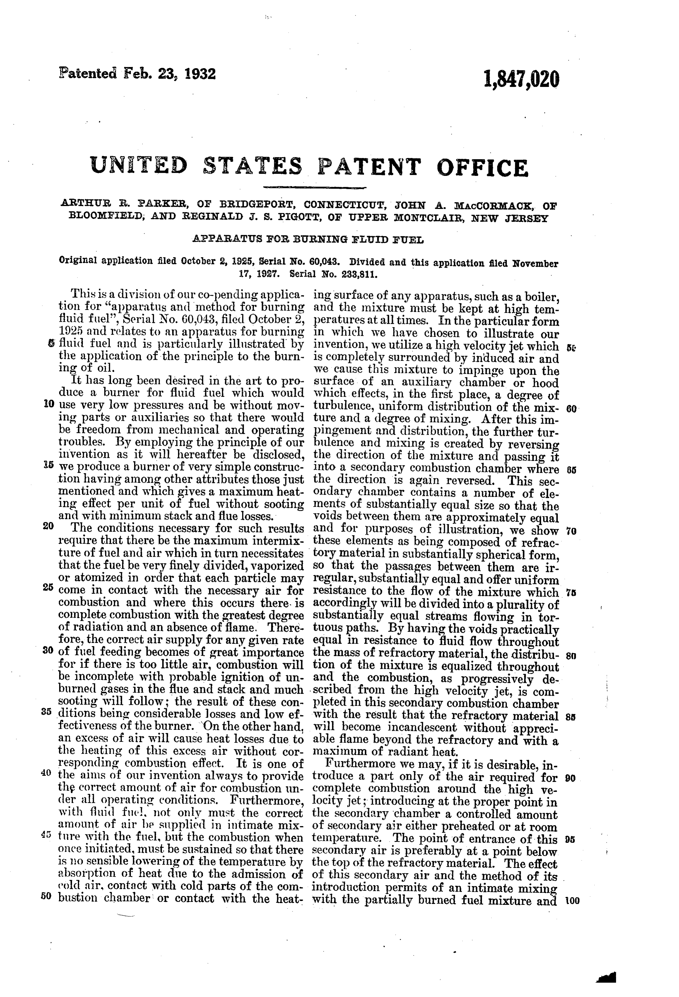
This is a division of our co-pending applica ing surface of any apparatus, such as a boiler, tion for “apparatus and method for burning and the mixture must be kept at high tem. fluid fuel”, Serial No. 60,043, filed October 2, peratures at all times. In the particular form 1925 and relates to an apparatus for burning in which we have chosen to illustrate our 5 fluid fuel and is particularly illustrated by invention, we utilize a high velocity jet which 55 the application of the principle to the burn is completely surrounded by induced air and ing of oil. we cause this mixture to impinge upon the It has long been desired in the art to pro surface of an auxiliary chamber or hood duce a burner for fluid fuel which would which effects, in the first place, a degree of i0 use very low pressures and be without mov turbulence, uniform distribution of the mix- 60. ing parts or auxiliaries s? that there would ture and a degree of mixing. After this im be freedom from mechanical and operating pingement and distribution, the further tur troubles. By employing the principle of our bulence and mixing is created by reversing invention as it will hereafter be disclosed, 5 we produce a burner of very simple construc the direction of the mixture and passing it into a secondary combustion chamber where 65 tion having among other attributes those just the direction is again reversed. This sec mentioned and which gives a maximum heat ondary chamber contains a number of ele ing effect per unit of fuel without sooting ments of substantially equal size so that the and with minimum stack and flue losses.
20) The conditions necessary for such results voids between them are approximately equal and for purposes of illustration, we show 70 require that there be the maximum intermix these elements as being composed of refrac ture of fuel and air which in turn necessitates tory material in substantially spherical form, that the fuel be very finely divided, vaporized so that the passages between them are ir or atomized in order that each particle may regular, substantially equal and offer uniform 25 come in contact with the necessary air for resistance to the flow of the mixture which 75 combustion and where this occurs there is accordingly will be divided into a plurality of complete combustion with the greatest degree substantially equal streams flowing in tor of radiation and an absence of flame. There tuous paths. By having the voids practically fore, the correct air supply for any given rate equal in resistance to fluid flow throughout 30 of fuel feeding becomes of great importance the mass of refractory material, the distribu 8 for if there is too little air, combustion will tion of the mixture is equalized throughout be incomplete with probable ignition of un and the combustion, as progressively de burned gases in the fue and stack and much scribed from the high velocity jet, is com sooting will follow; the result of these con pleted in this secondary combustion chamber 35 ditions being considerable losses and low ef with the result that the refractory material 8.
fectiveness of the burner. On the other hand, will become incandescent without appreci an excess of air will cause heat losses due to able flame beyond the refractory and with a the heating of this excess air without cor maximum of radiant heat.
responding combustion effect. It is one of Furthermore we may, if it is desirable, in
the aims of our invention always to provide troduce a part only of the air required for 90 th? correct amount of air for combustion un complete combustion around the high ve der all operating conditions. Furthermore, locity jet; introducing at the proper point in with fluid fue not only must the correct the secondary chamber a controlled amount amount of air be supplied in intimate mix of secondary air either preheated or at room ture with the fuel, but the combustion when temperature. The point of entrance of this 95 once initiated, must be sustained so that there secondary air is preferably at a point below is no sensible lowering of the temperature by the top of the refractory material. The effect absorption of heat due to the admission of of this secondary air and the method of its cold air, contact with cold parts of the com introduction permits of an intimate mixing 50 bustion chamber or contact with the heat with the partially burned fuel mixture and 00
Page 6
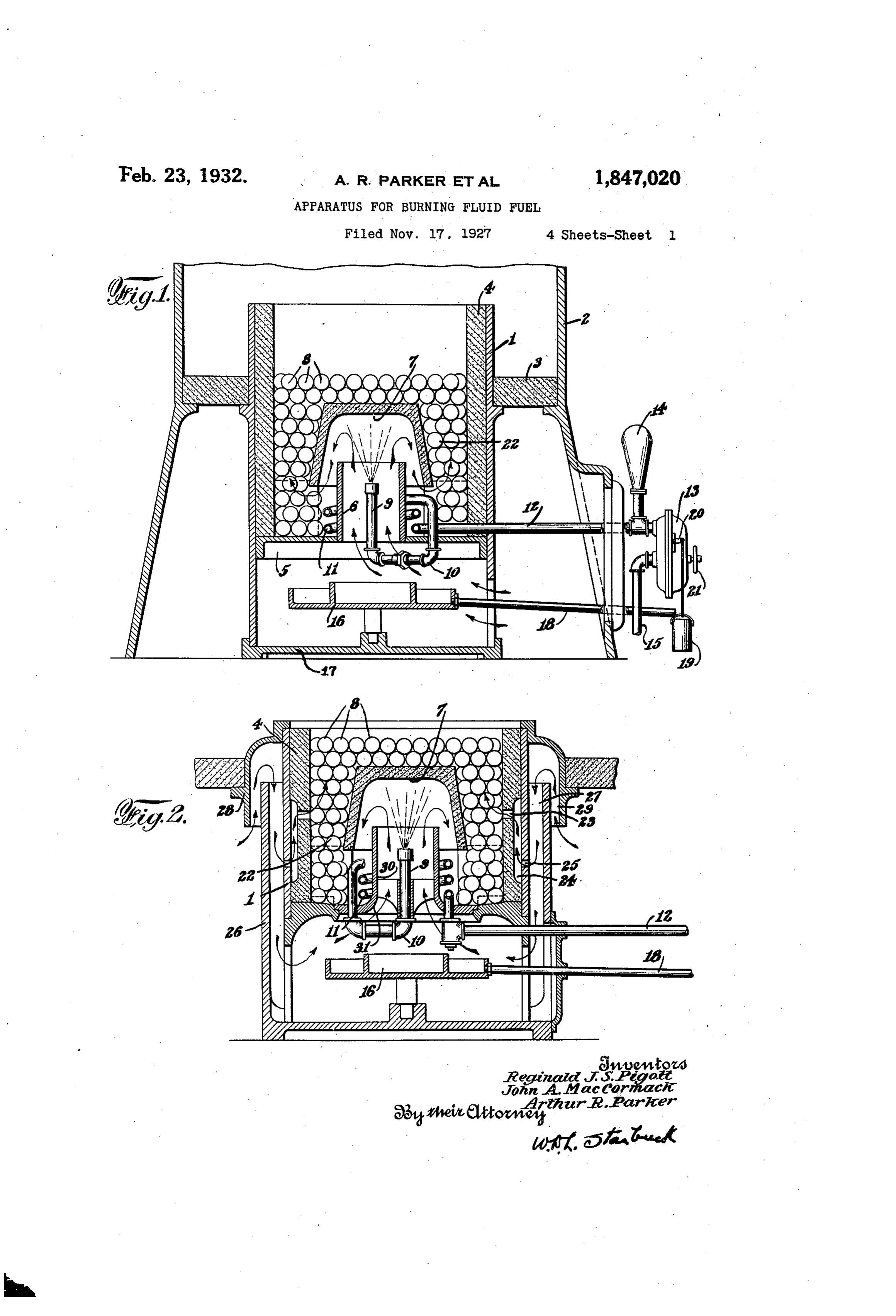
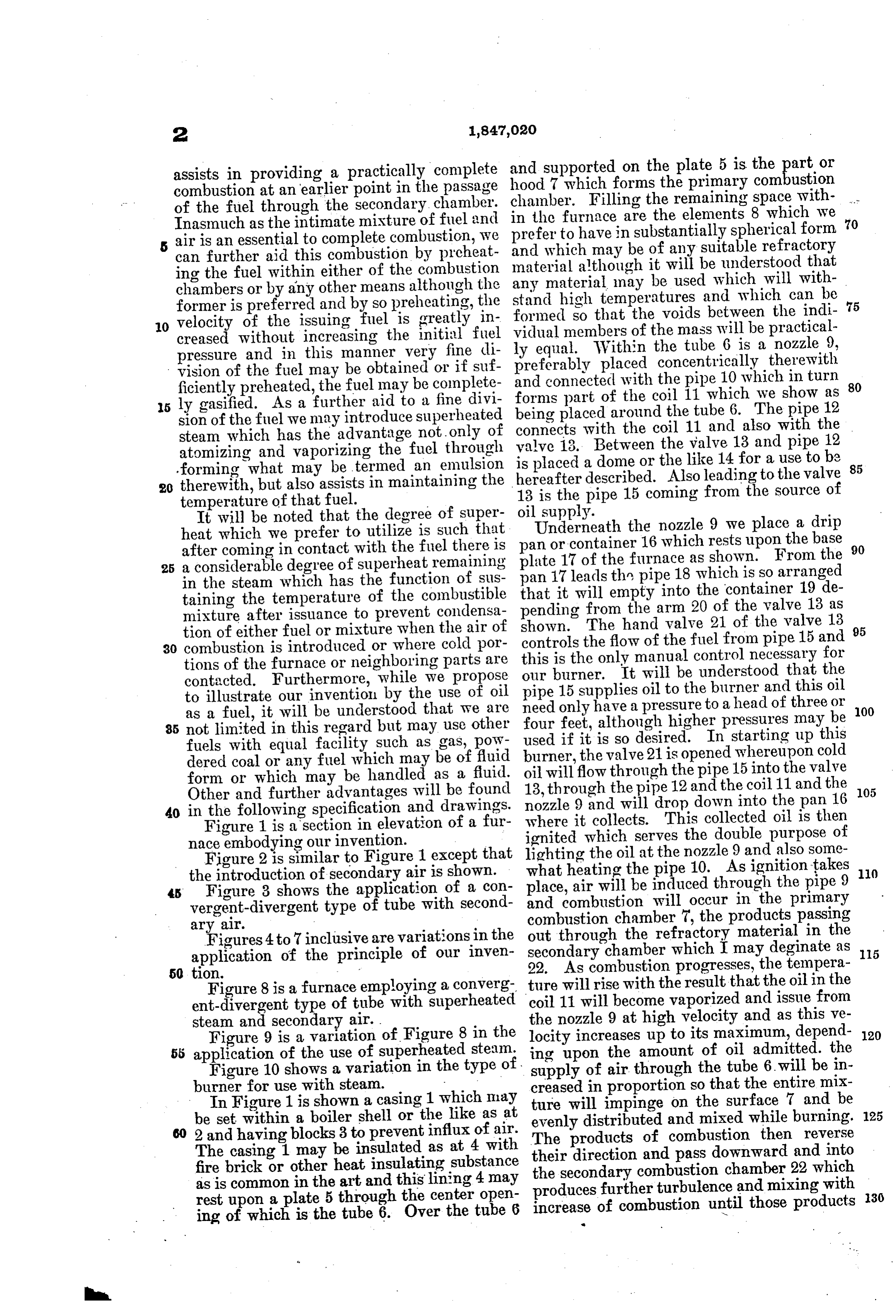
assists in providing a practically complete and hood supported on the plate 5 is the part or 7 which forms the primary combustion combustion at an earlier point in the passage chamber. Filling the remaining space with of the fuel through the secondary chamber. in the furnace
Inasmuch as the intimate mixture of fuel and prefer to have inare the elements 8 which we 70 substantially spherical form air is an essential to complete combustion, we can further aid this combustion by preheat and which may be of any suitable refractory material although it will be understood that ing the fuel within either of the combustion any chambers or by any other means although the standmaterial may be used which will with former is preferred and by so preheating, the formedhigh temperatures and which can be so that the voids between the indi
O velocity of the issuing fuel is greatly in vidual members of the mass will be practical creased without increasing the initial fuel ly equal. Within the tube 6 is a nozzle 9, pressure and in this manner very fine di preferably placed concentrically therewith vision of the fuel may be obtained or if suf and connected with the pipe 10 which in turn ficiently preheated, the fuel may be complete forms part of the coil 11 which we show as 80 5 ly gasified. As a further aid to a fine divi being placed around the tube 6. The pipe 12 sion of the fuel we may introduce superheated connects with the coil 11 and also with the steam which has the advantage not only of valve 13. Between the valve 13 and pipe 12 atomizing and vaporizing the fuel through is placed a dome or the like 14 for a use to be forming what may be termed an emulsion hereafter described. Also leading to the valve 85 20 therewith, but also assists in maintaining the temperature of that fuel. 13 is the pipe 15 coming from the source of It will be noted that the degree of super oilUnderneath supply.
heat which we prefer to utilize is such that pan or containerthe16 nozzle which 9 we place a drip rests upon the base 90 after coming in contact with the fuel there is plate 17 of the furnace as shown. From the 25 a considerable degree of superheat remaining in the steam which has the function of Sus pan 17 leads the pipe 18 which is so arranged taining the temperature of the combustible that it will empty into the container 19 de mixture after issuance to prevent condensa pending from the arm 20 of the valve 13 as tion of either fuel or mixture when the air of shown. The hand valve 21 of the valve 13 95 30 combustion is introduced or where cold por controls the flow of the fuel from pipe 15 and tions of the furnace or neighboring parts are this is the only manual control necessary for contacted. Furthermore, while we propose our burner. It will be understood that the to illustrate our invention by the use of oil pipe 15 supplies oil to the burner and this oil need only have a pressure to a head of three or 00 as a fuel, it will be understood that we are four feet, although higher pressures may be 85 not limited in this regard but may use other fuels with equal facility such as gas, pow used burner, if it is so desired. In starting up this the valve 21 is opened whereupon cold dered coal or any fuel which may be of fluid oil will flow form or which may be handled as a fluid. 13, through through the pipe the pipe 15 into the valve 12 and the coil 11 and the 105
Other and further advantages will be found nozzle 9 and will drop down into the pan 16 40 in the following specification and drawings.
Figure 1 is a section in elevation of a fur where it collects. This collected oil is then nace embodying our invention. - ignited which serves the double purpose of lighting the oil at the nozzle 9 and also some
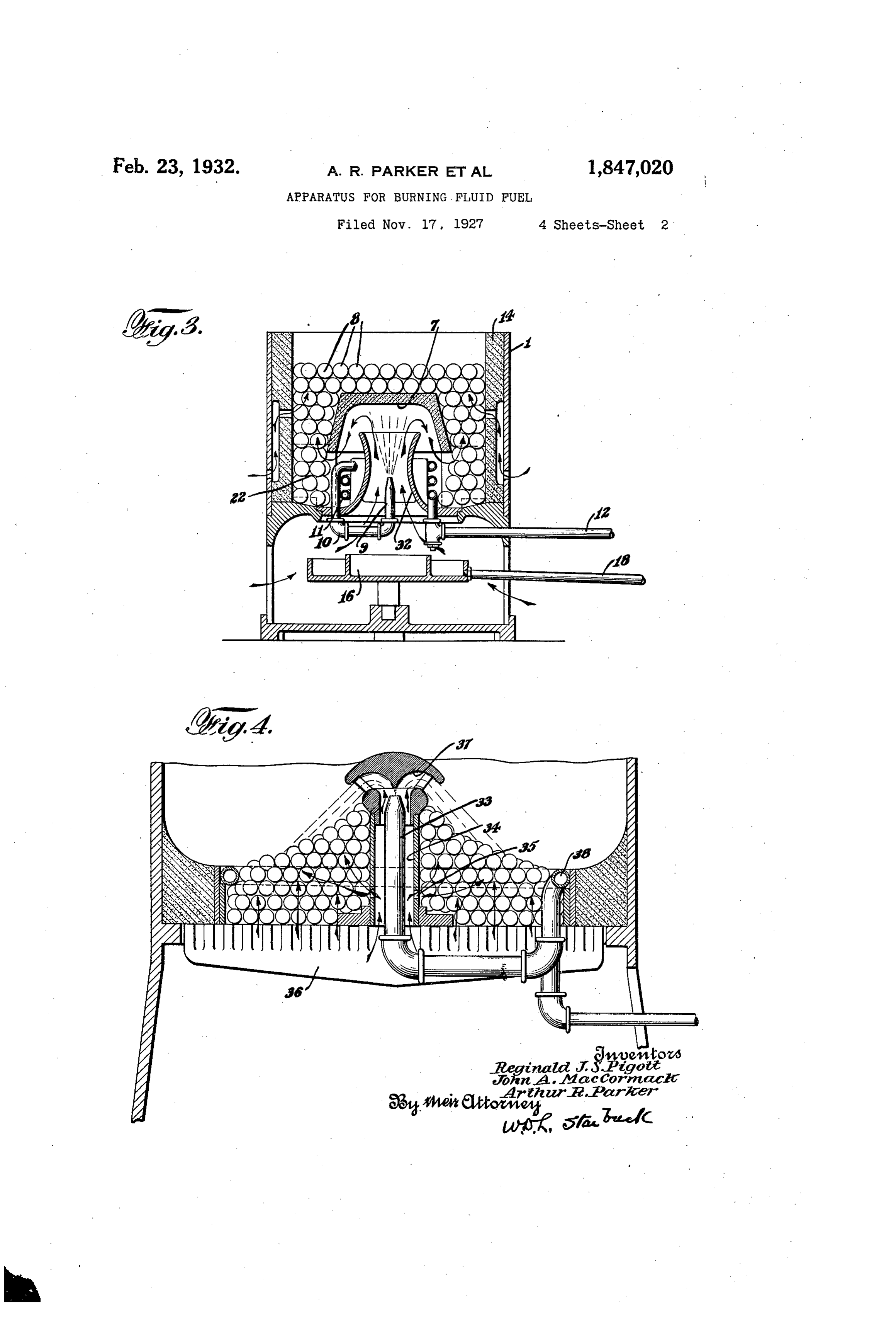
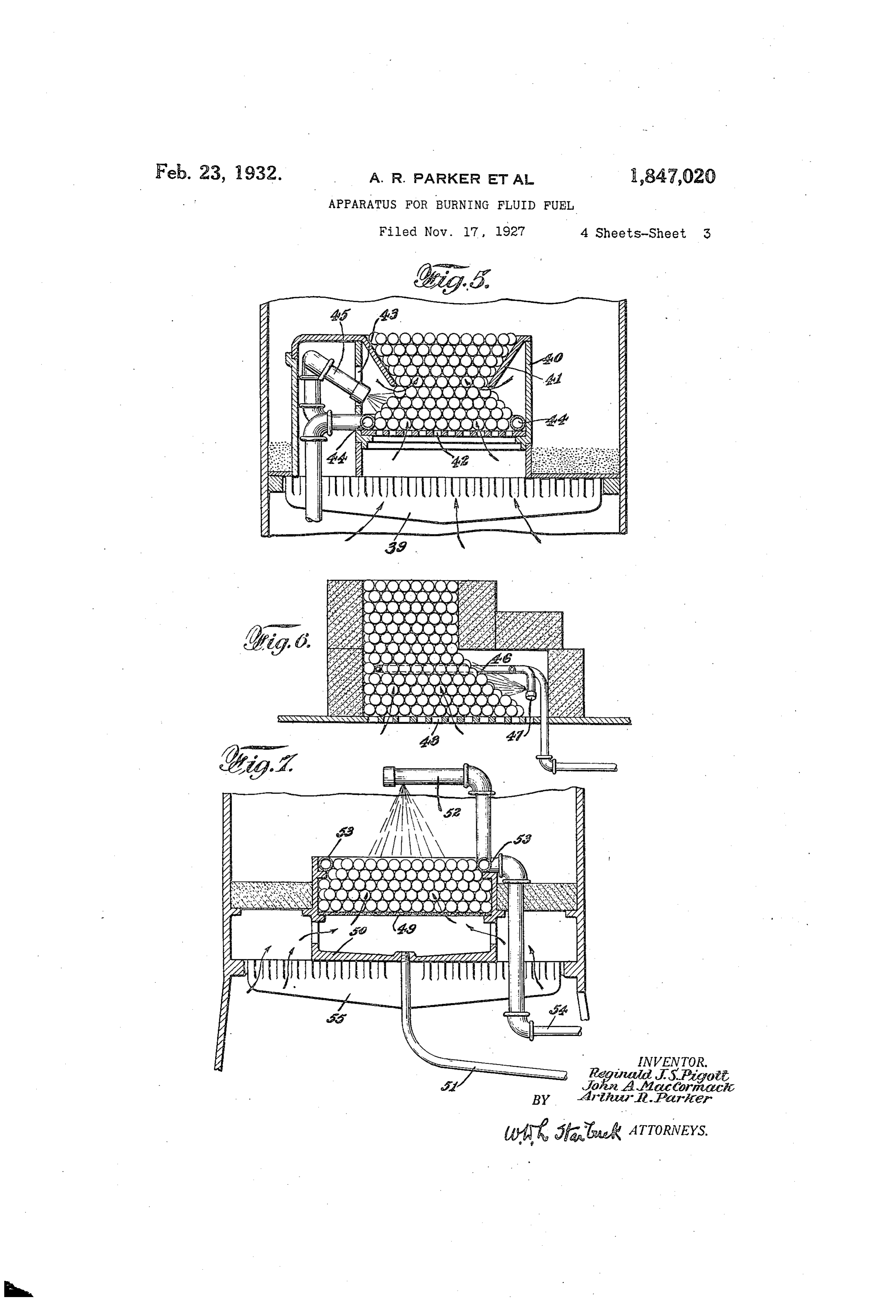
Figure 2 is similar to Figure 1 except that what the introduction of secondary air is shown. place,heating the pipe 10. As ignition takes () air will be induced through the pipe 9 45 Figure 3 shows the application of a con and combustion will occur in the primary vergent-divergent type of tube with second combustion chamber 7, the products passing ary a?r. out through the refractory material in the Figures 4 to 7 inclusive are variations in the secondary chamber which I may deginate as 15 application of the principle of our inven 22. As combustion progresses, the tempera
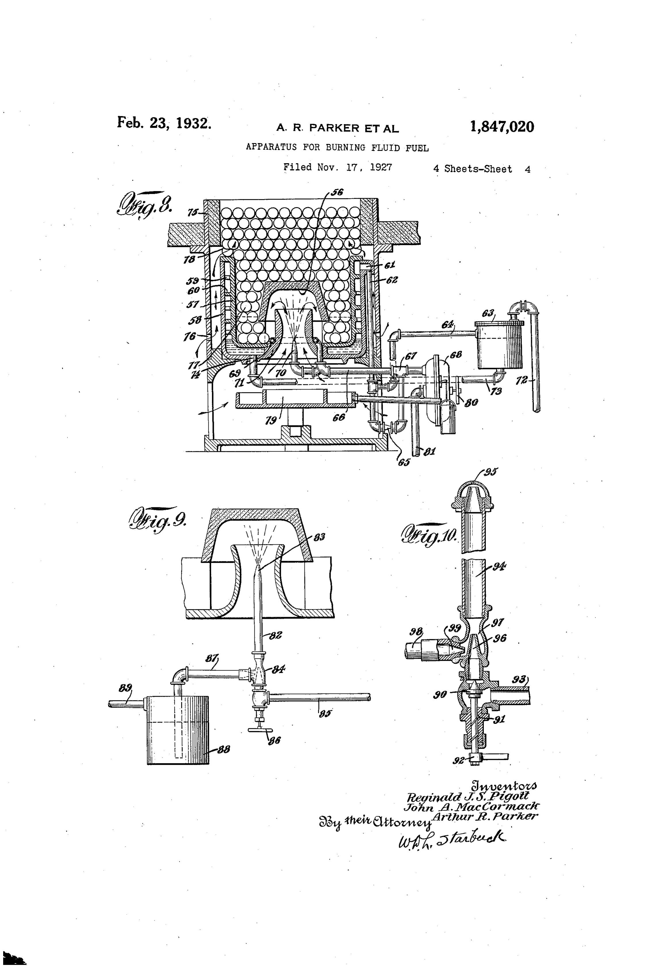
Figure 8 is a furnace employing a converg ture will rise with the result that the oil in the ent-divergent type of tube with superheated coil 11 will become vaporized and issue from steam and secondary air. . the nozzle 9 at high velocity and as this ve Figure 9 is a variation of Figure 8 in the locity increases up to its maximum, depend 120 55 application of the use of superheated steam, ing upon the amount of oil admitted. the Figure 10 shows a variation in the type of supply of air through the tube 6. will be in burner for use with steam. - creased in proportion so that the entire mix In Figure 1 is shown a casing 1 which may ture will impinge on the surface 7 and be be set within a boiler shell or the like as at evenly distributed and mixed while burning. 2 and having blocks 3 to prevent influx of air. The products of combustion then reverse The casing 1 may be insulated as at 4 with their direction and pass downward and into fire brick or other heat insulating substance the secondary combustion chamber 22 which as is common in the art and this lining 4 may produces further turbulence and mixing with rest upon a plate 5 through the center open increase of combustion until those products 30 ing of which is the tube 6. Over the tube 6 w
Page 7
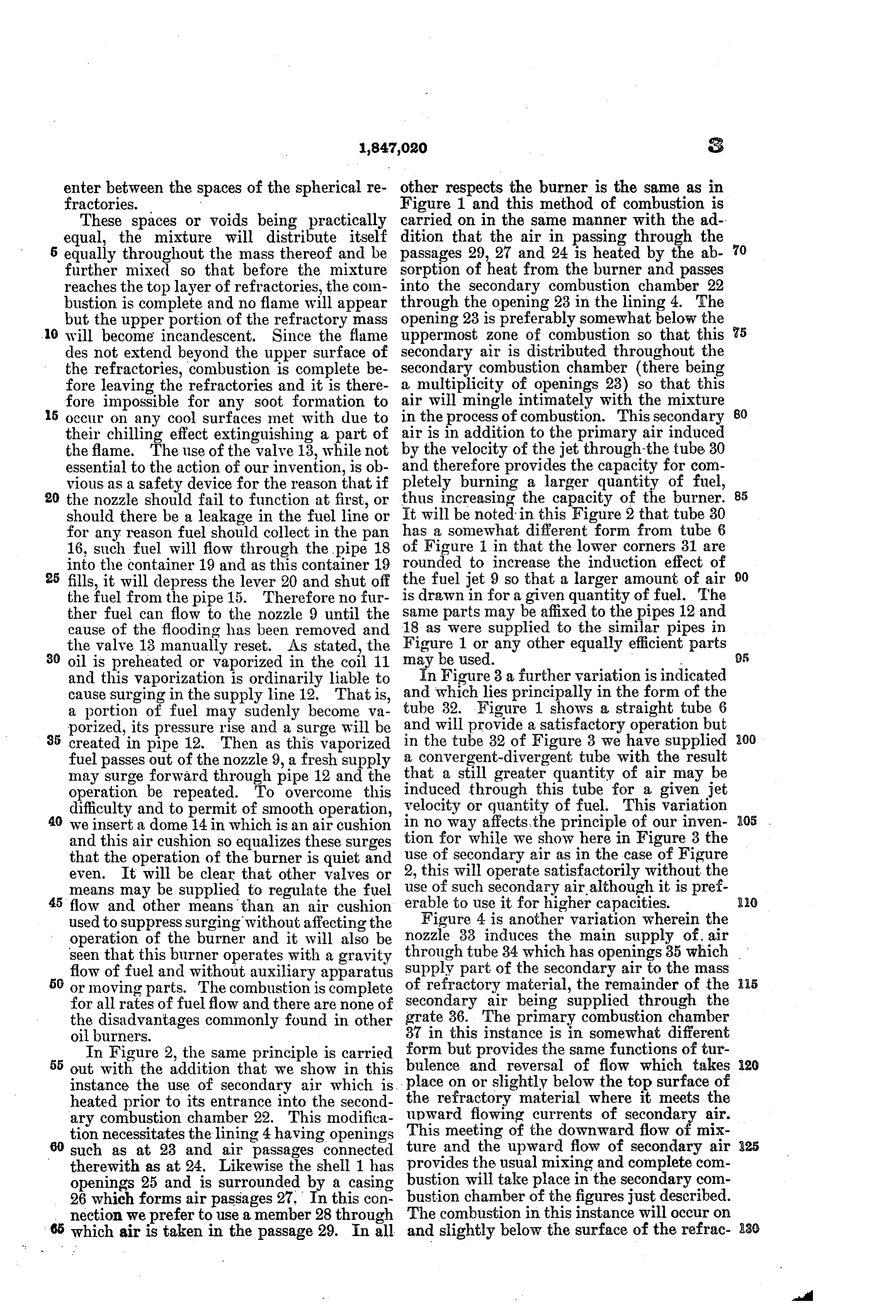
enter between the spaces of the spherical re other respects the burner is the same as in fractories. Figure 1 and this method of combustion is These spaces or voids being practically carried on in the same manner with the ad equal, the mixture will distribute itself dition that the air in passing through the 5 equally throughout the mass thereof and be passages 29, 27 and 24 is heated by the ab further mixed so that before the mixture sorption of heat from the burner and passes reaches the top layer of refractories, the colm into the secondary combustion chamber 22 bustion is complete and no flame will appear through the opening 23 in the lining 4. The but the upper portion of the refractory mass opening 23 is preferably somewhat below the 10 will become incandescent. Since the flame uppermost zone of combustion so that this des not extend beyond the upper surface of secondary air is distributed throughout the the refractories, combustion is complete be secondary combustion chamber (there being fore leaving the refractories and it is there a multiplicity of openings 23) so that this fore impossible for any soot formation to air will mingle intimately with the mixture 80 15 occur on any cool surfaces met with due to in the process of combustion. This secondary their chilling effect extinguishing a part of air is in addition to the primary air induced the flame. The use of the valve 13, while not by the velocity of the jet through-the tube 30 essential to the action of our invention, is ob and therefore provides the capacity for com vious as a safety device for the reason that if pletely burning a larger quantity of fuel, 85 20 the nozzle should fail to function at first, or thus increasing the capacity of the burner. should there be a leakage in the fuel line or hasIt will be noted in this Figure 2 that tube 30 for any reason fuel should collect in the pan a somewhat different form from tube 6 16, such fuel will flow through the pipe 18 of Figure 1 in that the lower corners 31 are into the container 19 and as this container 19 rounded to increase the induction effect of 25 fills, it will depress the lever 20 and shut off the fuel jet 9 so that a larger amount of air O the fuel from the pipe 15. Therefore no fur is drawn in for a given quantity of fuel. The ther fuel can flow to the nozzle 9 until the same parts may be affixed to the pipes 12 and cause of the flooding has been removed and 18 as were supplied to the similar pipes in the valve 13 manually reset. As stated, the Figure 1 or any other equally efficient parts 95 80 oil is preheated or vaporized in the coil 11 may be used.
and this vaporization is ordinarily liable to In Figure 3 a further variation is indicated cause surging in the supply line 12. That is, and which lies principally in the form of the a portion of fuel may sudenly become va tube 32. Figure 1 shows a straight tube 6 porized, its pressure rise and a surge will be and will provide a satisfactory operation but 35 created in pipe 12. Then as this vaporized in the tube 32 of Figure 3 we have supplied 300 fuel passes out of the nozzle 9, a fresh supply a convergent-divergent tube with the result may surge forward through pipe 12 and the that a still greater quantity of air may be operation be repeated. To overcome this induced through this tube for a given jet difficulty and to permit of smooth operation, velocity or quantity of fuel. This variation 40 we insert a dome 14 in which is an air cushion in no way affects, the principle of our inven 05 and this air cushion so equalizes these surges tion for while we show here in Figure 3 the that the operation of the burner is quiet and 2,usethis of secondary air as in the case of Figure will operate satisfactorily without the even. It will be clear that other valves or means may be supplied to regulate the fuel use of such secondary air although it is pref 45 flow and other means than an air cushion erable to use it for higher capacities. used to suppress surging without affecting the Figure 4 is another variation wherein the operation of the burner and it will also be nozzle 33 induces the main supply of air seen that this burner operates with a gravity through tube 34 which has openings 35 which flow of fuel and without auxiliary apparatus supply part of the secondary air to the mass or moving parts. The combustion is complete of refractory material, the remainder of the for all rates of fuel flow and there are none of secondary air being supplied through the the disadvantages commonly found in other grate 36. The primary combustion chamber 3 in this instance is in somewhat different oil burners.
In Figure 2, the same principle is carried form but provides the same functions of tur out with the addition that we show in this bulence and reversal of flow which takes 20 instance the use of secondary air which is place on or slightly below the top surface of heated prior to its entrance into the second the refractory material where it meets the upward flowing currents of secondary air.
ary combustion chamber 22. This modifica tion necessitates the lining 4 having openings This meeting of the downward flow of mix 25 60 such as at 23 and air passages connected ture and the upward flow of secondary air therewith as at 24. Likewise the shell 1 has provides the usual mixing and complete com openings 25 and is surrounded by a casing bustion will take place in the secondary com 26 which forms air passages 27. In this con The bustion chamber of the figures just described. nection we prefer to use a member 28 through combustion in this instance will occur on 65 which air is taken in the passage 29. In all and slightly below the surface of the refrac- 280
Page 8
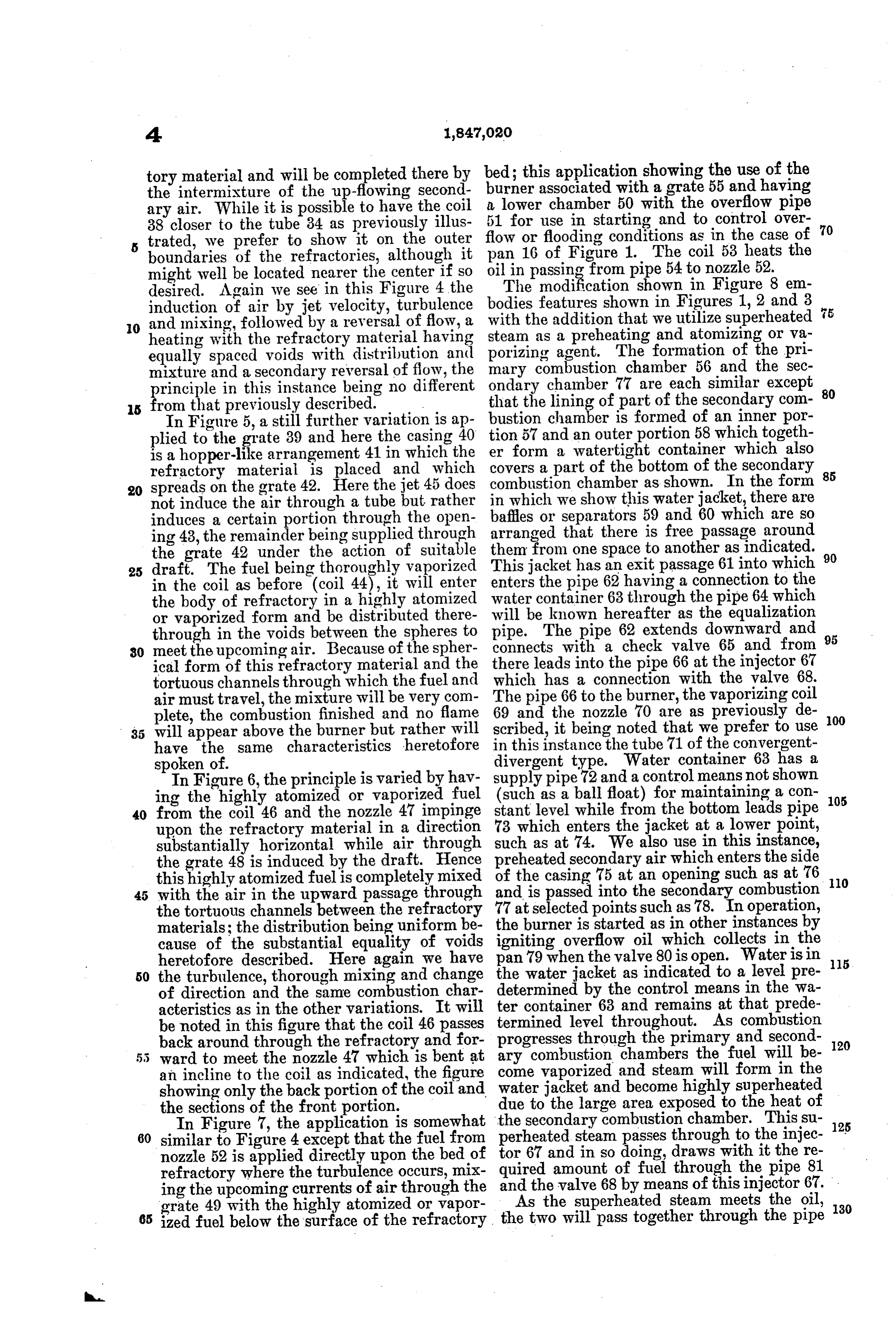
tory material and will be completed there by bed; this application showing the use of the the intermixture of the up-flowing second a lowerassociated burner with a grate 55 and having chamber 50 with the overflow pipe ary air. While it is possible to have the coil 51 for use in starting and to control over 38 closer to the tube 34 as previously illus trated, we prefer to show it on the outer flow or flooding conditions as in the case of 70 boundaries of the refractories, although it oil pan 16 of Figure 1. The coil 53 heats the might well be located nearer the center if so The in passing from pipe 54 to nozzle 52. desired. Again we see in this Figure 4 the modification shown in Figure 8 em induction of air by jet velocity, turbulence bodies features shown in Figures 1, 2 and 3 O and mixing, followed by a reversal of flow, a with the addition that we utilize superheated heating with the refractory material having steam as a preheating and atomizing or va equally spaced voids with distribution and porizing agent. The formation of the pri mary combustion chamber 56 and the sec mixture and a secondary reversal of flow, the ondary principle in this instance being no different that the chamberlining of 77 are each similar except 80 part of the secondary com 5 from that previously described.
In Figure 5, a still further variation is ap bustion chamber is formed of an inner por plied to the grate 39 and here the casing 40 tion 57 and an outer portion 58 which togeth is a hopper-like arrangement 41 in which the er form a watertight container which also refractory material is placed and which covers a part of the bottom of the secondary 85 combustion chamber as shown. In the form 20 spreads on the grate 42. Here the jet 45 does not induce the air through a tube but rather in which we show this water jacket, there are induces a certain portion through the open baffles or separators 59 and 60 which are so ing 43, the remainder being supplied through arranged that there is free passage around the grate 42 under the action of suitable them from one space to another as indicated. 90 25 draft. The fuel being thoroughly vaporized This jacket has an exit passage 61 into which in the coil as before (coil 44), it will enter enters the pipe 62 having a connection to the the body of refractory in a highly atomized water container 63 through the pipe 64 which or vaporized form and be distributed there will be known hereafter as the equalization through in the voids between the spheres to pipe. The pipe 62 extends downward and 95 30 meet the upcoming air. Because of the spher connects with a check valve 65 and from ical form of this refractory material and the there leads into the pipe 66 at the injector 67 which has a connection with the valve 68.
tortuous channels through which the fuel and The pipe 66 to the burner, the vaporizing coil air must travel, the mixture will be very com plete, the combustion finished and no flame 69 and the nozzle 70 are as previously de OO 35 will appear above the burner but rather will scribed, it being noted that we prefer to use have the same characteristics heretofore in this instance the tube 71 of the convergent spoken of. divergent type. Water container 63 has a In Figure 6, the principle is varied by hav supply pipe 72 and a control means not shown ing the highly atomized or vaporized fuel (such as a ball float) for maintaining a con 105 40 from the coil 46 and the nozzle 47 impinge stant level while from the bottom leads pipe upon the refractory material in a direction 73 which enters the jacket at a lower point, substantially horizontal while air through such as at 74. We also use in this instance, the grate 48 is induced by the draft. Hence preheated secondary air which enters the side this highly atomized fuelis completely mixed of the casing 75 at an opening such as at 76 10 with the air in the upward passage through and is passed into the secondary combustion the tortuous channels between the refractory 77 at selected points such as 78. In operation, materials; the distribution being uniform be the burner is started as in other instances by cause of the substantial equality of voids igniting overflow oil which collects in the heretofore described. Here again we have pan 79 when the valve 80 is open. Waterisin 15 50 the turbulence, thorough mixing and change the water jacket as indicated to a level pre of direction and the same combustion char determined by the control means in the wa acteristics as in the other variations. It will ter container 63 and remains at that prede be noted in this figure that the coil 46 passes termined level throughout. As combustion back around through the refractory and for progresses through the primary and second 120 ward to meet the nozzle 47 which is bent at ary combustion chambers the fuel will be an incline to the coil as indicated, the figure come vaporized and steam will form in the water jacket and become highly superheated showing only the backportion of the coil and due to the large area exposed to the heat of the sections of the front portion. the secondary combustion chamber. This su 125 In Figure 7, the application is somewhat 60 similar to Figure 4 except that the fuel from perheated steam passes through to the injec nozzle 52 is applied directly upon the bed of tor 67 and in so doing, draws with it the re refractory where the turbulence occurs, mix quired amount of fuel through the pipe 81 ing the upcoming currents of air through the andAsthethevalve 68 by means of this injector 67. . superheated steam meets the oil, 30 grate 49 with the highly atomized or vapor the two will pass together through the pipe 65 ized fuel below the surface of the refractory
Page 9
66 and in this passage the oil becomes heated will accomplish a degree of combustion be and vaporized and the steam will lose apor yond what has yet been possible with but tion of its superheat in heating the oil but one control; namely, a control of the steam as before mentioned, this superheat is of such only, which may be accomplished in a vari 5 degree that no condensation occurs during ety of ways such as by a thermo-couple or O the process. The superheated steam and va by pressure means or other regulating de porized oil pass through the coil 69 where WCeS.
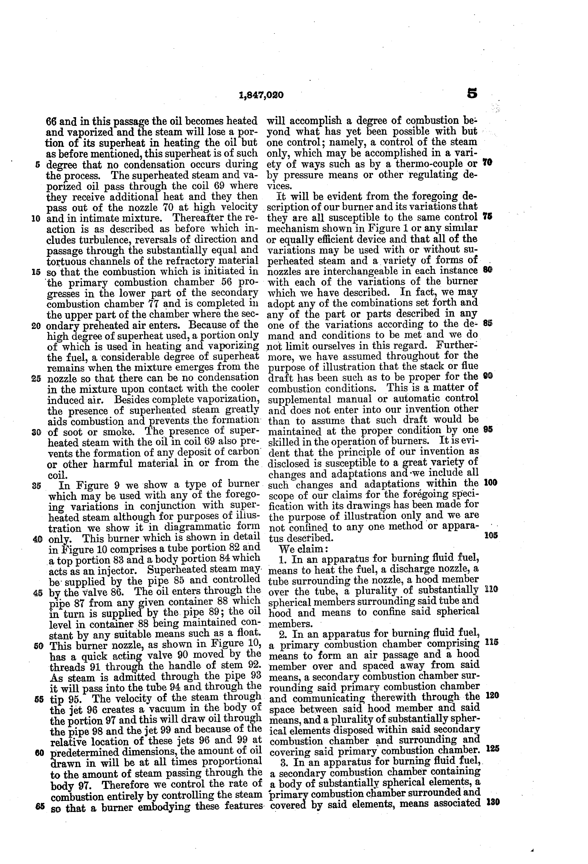
they receive additional heat and they then It will be evident from the foregoing de pass out of the nozzle 70 at high velocity scription of our burner and its variations that O and in intimate mixture. Thereafter the re they are all susceptible to the same control s action is as described as before which in mechanism shown in Figure 1 or any simular cludes turbulence, reversals of direction and or equally efficient device and that all of the passage through the substantially equal and variations may be used with or without su tortuous channels of the refractory material perheated steam and a variety of forms of 15 so that the combustion which is initiated in nozzles are interchangeable in each instance the primary combustion chamber 56 pro with each of the variations of the burner gresses in the lower part of the secondary which we have described. In fact, we may combustion chamber 77 and is completed in adopt any of the combinations set forth and the upper part of the chamber where the sec any of the part or parts described in any 85 20 ondary preheated air enters. Because of the one of the variations according to the de high degree of superheat used, a portion only mand and conditions to be metand we do of which is used in heating and vaporizing not limit ourselves in this regard. Further the fuel, a considerable degree of superheat more, we have assumed throughout for the remains when the mixture emerges from the purpose of illustration that the Stack or fue 25 nozzle so that there can be no condensation draft has been such as to be proper for the in the mixture upon contact with the cooler combustion conditions. This is a matter of induced air. Besides complete vaporization, supplemental manual or automatic control the presence of superheated steam greatly and does not enter into our invention other aids combustion and prevents the formation than to assume that such draft would be 3. of soot or smoke. The presence of Super maintained at the proper condition by one 95 heated steam with the oil in coil 69 also pre skilled in the operation of burners. It is evi vents the formation of any deposit of carbon dent that the principle of our invention as or other harmful material in or from the disclosed is susceptible to a great variety of coil. changes and adaptations and we include all 35 In Figure 9 we show a type of burner. such changes and adaptations within the 00 which may be used with any of the forego scope of our claims for the forégoing speci ing variations in conjunction with super fication with its drawings has been made for heated steam although for purposes of illus the purpose of illustration only and we are tration we show it in diagrammatic form not confined to any one method or appara 05 inonly. This10burner figure which comprises is shown a tube in detail tusWedescribed.
portion,82and claim:
a top portion 83 and a body portion 84 which 1. In an apparatus for burning fluid fuel, acts as an injector. Superheated Steam may means to heat the fuel, a discharge nozzle, a be supplied by the pipe 85 and controlled tube surrounding the nozzle, a hood member by the valve 86. The oil enters through the over the tube, a plurality of substantially pipe 87 from any given container 88which hood andmembers spherical surrounding said tube and in turn is supplied by the pipe 89; the oil means to confine said spherical level in container 88being maintained con members.
stant by any suitable means Such as a float 2. In an apparatus for burning fluid fuel, 50 This birner nozzle, as shown in Figure 10, a primary combustion chamber comprising 5 has a quick acting valve 90 moved by the membermeans to form an air passage and a hood over and spaced away from said threads 91 through the handle of stem 92
As steam is admitted through the pipe 98 means, a secondary combustion chamber sur it will pass into the tube 94 and through the rounding said primary combustion chamber 55 tip 95. The velocity of the steam through and communicating therewith through the 120 the jet 96 creates ayacuum in the body of space between said hood member and said the portion 97 and this will draw oil through means, and a plurality of substantially spher the pipe 98 and the jet 99 and because of the ical elements disposed within said secondary relative location of these jets 96 and 99 at combustion chamber and surrounding and 25 predetermined dimensions, the amount of oil covering said primary combustion chamber. drawn in will be at all times proportional 3. In an apparatus for burning fluid-fuel, to the amount of steam passing through the a secondary combustion chamber containing body 97. Therefore we control the rate of a body of substantially spherical elements, a combustion entirely by controlling the steam primary combustion chamber surrounded and 130 65 so that a burner embodying these features covered by said elements, means associated
Page 10
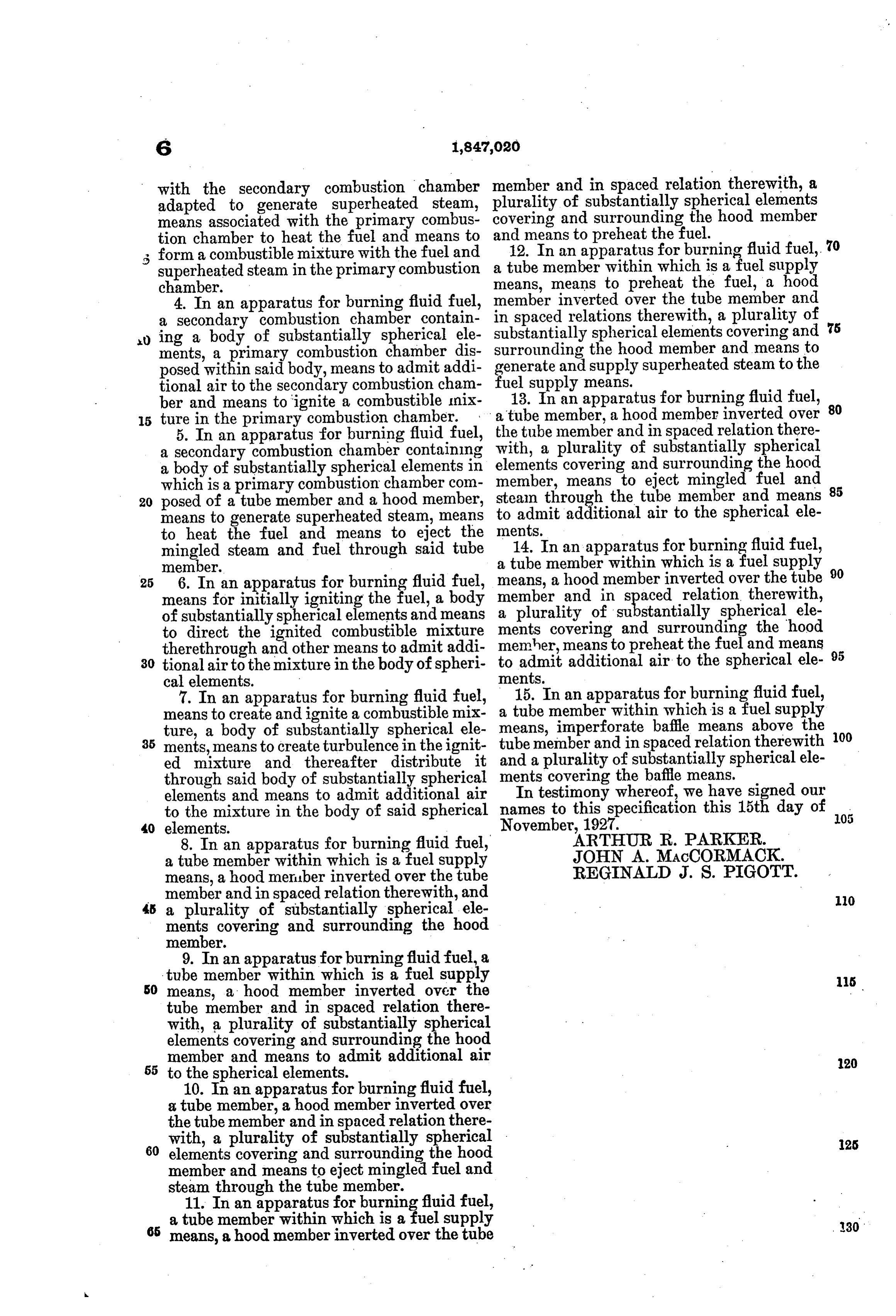
with the secondary combustion chamber member and in spaced relation therewith, a adapted to generate superheated steam, plurality of substantially spherical elements means associated with the primary combus covering and surrounding the hood member tion chamber to heat the fuel and means to and means to preheat the fuel. form a combustible mixture with the fuel and 12. In an apparatus for burning fluid fuel, 70 superheated steam in the primary combustion a tube member within which is a fuel supply chamber. means, means to preheat the fuel, a hood 4. In an apparatus for burning fluid fuel, member inverted over the tube member and a secondary combustion chamber contain in spaced relations therewith, a plurality of ing a body of substantially spherical ele substantially spherical elements covering and 75 ments, a primary combustion chamber dis surrounding the hood member and means to posed within said body, means to admit addi generate and supply superheated steam to the tional air to the secondary combustion cham fuel13.supply means.
ber and means to ignite a combustible mix a tube Inmember, an apparatus for burning fluid fuel, 80 a hood member inverted over ture in the primary combustion chamber.
the tube member and in spaced relation there 5. In an apparatus for burning fluid fuel, with, a secondary combustion chamber containing a plurality of substantially spherical a body of substantially spherical elements in elements covering and surrounding the hood which is a primary combustion chamber com member, means to eject mingled fuel and 85 20 posed of a tube member and a hood member, steam through the tube member and means means to generate superheated steam, means to admit additional air to the spherical ele to heat the fuel and means to eject the ments.
mingled steam and fuel through said tube 14. In an apparatus for burning fluid fuel, member. a tube member within which is a fuel supply 25 6. In an apparatus for burning fluid fuel, means, a hood member inverted over the tube 90 means for initially igniting the fuel, a body member and in spaced relation therewith, a plurality of substantially spherical ele of substantially spherical elements and means ments to direct the ignited combustible mixture memher,coveringmeans to and surrounding the hood preheat the fuel and means therethrough and other means to admit addi 30 tional air to the mixture in the body of spheri to admit additional air to the spherical ele 95
7. In an apparatus for burning fluid fuel, 15. In an apparatus for burning fluid fuel, means to create and ignite a combustible mix ameans, tube member within which is a fuel supply imperforate baffle means above the ture, a body of substantially spherical ele 35 ments, means to create turbulence in the ignit tube member and in spaced relation therewith 100 ed mixture and thereafter distribute it and a plurality of substantially spherical ele through said body of substantially spherical ments covering the baffle means. elements and means to admit additional air In testimony whereof, we have signed our to the mixture in the body of said spherical names to this specification this 15th day of 105 40 elements. November,ARTHUR.
8. In an apparatus for burning fluid fuel, JOHN A. MACCORMACK. a tube member within which is a fuel supply REGINALD J. S. PIGOTT. means, a hood member inverted over the tube member and in spaced relation therewith, and 45 a plurality of substantially spherical elle 10 ments covering and surrounding the hood member.
9. In an apparatus for burning fluid fuel, a tube member within which is a fuel supply 50 means, a hood member inverted over the 115 tube member and in spaced relation there with, a plurality of substantially spherical elements covering and surrounding the hood member and means to admit additional air 20 55 to the spherical elements.
10. In an apparatus for burning fluid fuel, a tube member, a hood member inverted over the tube member and in spaced relation there with, a plurality of substantially spherical 60 elements covering and surrounding the hood 25 member and means to eject mingled fuel and steam through the tube member.
11. In an apparatus for burning fluid fuel,
a tube member within which is a fuel supply means, a hood member inverted over the tube
Provenance
- Collection
- Cited prior art
- Original PDF
- patentimages.storage.googleapis.com →
- Filed
- 1927-11-17
- Pages
- 10
- Method
- pdftotext (the PDF's own text layer) + pdftoppm 300dpi page scans
- Source
- Google Patents bibliographic record
- Granted
- 1932-02-23
- Inventors
- Arthur R Parker; John A Maccormack; Reginald J S Pigott
- Transcribed from
- patentimages.storage.googleapis.com →