patent · US4702808
Chemical reaction apparatus and method
27 October 1987
Page 1 — bibliographic record
United States Patent (19) 11 Patent Number: 4,702,808 Lemelson 45 Date of Patent: Oct. 27, 1987
54 CHEMICAL REACTION APPARATUS AND 58) Field of Search ................. 204/157. 1 R, 157.1 L, METHOD 204/158 R, 158 L, 193, 157.41, 157.42, 157.62,
76 Inventor: Jerome H. Lemelson, 85 Rector St., 56) References Cited Metuchen, N.J. 08840 U.S. PATENT DOCUMENTS 21 Appl. No.: 712,411 3,405,045 10/1968 Hoskins ........................... 204/158 L 3,528,897 9/1970 Scheiner ... 204/158 L 22 Filed: Mar. 15, 1985 4,012,301 3/1977 Rich et al..... ... 204/158 L Primary Examiner-Howard S. Williams
Related U.S. Application Data 57 ABSTRACT 63) Continuation-in-part of Ser. No. 592,968, Mar. 23, This invention concerns an apparatus and method for 1984, Pat. No. 4,666,678, and a continuation of Ser. No. reacting on matter, particularly to change its chemical 737,446, Oct. 29, 1976, which is a continuation of Ser. properties and to create chemical reactions with respect No. 165,445, Jul. 26, 1971, abandoned, and a continua to such matter by introducing the matter into a reaction tion-in-part of Ser. No. 12,082, Feb. 17, 1970, aban chamber as one or more streams of particles, gas, liquid doned, which is a continuation-in-part of Ser. No. or plasma or a combination of such forms of matter and 710,518, Mar. 5, 1968, Pat. No. 3,566,645, which is a reacting on such matter by directing one or more beams continuation-in-part of Ser. No. 501,395, Oct. 22, 1965,
Pat. No. 3,371,404, which is a continuation-in-part of of radiant energy, such as coherent light energy gener Ser. No. 668,561, Jun. 27, 1957, abandoned. ated by a laser or a plurality of lasers wherein such radiant energy serves to initiate or complete the desired 51) Int. Cl. .............................................. B01J 19/12 chemical reaction.
52 U.S. C. .......................... 204/157.41; 204/157.42;
204/157.61; 204/157.62; 422/186 20 Claims, 12 Drawing Figures
Page 2
Drawing sheet — no readable text.
Page 3
Drawing sheet — no readable text.
Page 4
Accordingly it is a primary object of this invention to
CHEMICAL REACTION APPARATUS AND provide a new and improved apparatus and method for METHOD reacting on a fluent material with radiation generated as one or more collimated beams of such radiation and
CROSS REFERENCE TO RELATED directed into the fluent material.
APPLICATIONS Another object is to provide a new and improved This is a continuation-in-part of Ser. No. 592,968 filed chemical reaction apparatus and method involving a 3/23/84 now U.S. Pat. No. 4,666,678 and a continuation fluid or fluids and a high intensity beam of radiation wherein the radiation is caused to predeterminately of Ser. No. 737,446 filed 10/29/76 which is a continua 10 intersect and react on the chemical or chemicals of the
doned and a continuation-in-part of Ser. No. 05/012,082 Another object is to provide a chemical reaction filed 2/17/70, now abandoned which is a continuation apparatus which employs an intense light beam gener in-part of Ser. No. 04/710,518 filed 3/5/68 now U.S. ated by a laser intersecting a material which is continu Pat. No. 3,566,645 which is a continuation-in-part of 15 ously or intermittently fed through a reaction zone. Ser. No. 04/501,395 filed 10/22/63 (now U.S. Pat. No. Another object is to provide a method for effecting 3,371,404) which is a continuation-in-part of Ser. No. chemical reactions utilizing coherent light energy gen
erated by a laser.
DESCRIPTION OF THE PRIOR ART
Another object is to provide a method for effecting
Before the making the instant invention, it was ated by anreactions chemical electron utilizing a stream of electrons gener gun.
known to generate and effect chemical reactions in Another object is to provide a method for effecting a liquids and gases by such processes as combustion of such liquids and gases, by electrical ignition means, by chemical reaction using radiation generated in two or radio frequency energy applied from an external source 2.5 more different forms and caused to intersect material to of same, by the injection and ignition of fuel, by electri be reacted on thereby, either at the same location or at cal resistence heating and by heat transfer means ener selected locations, one of which is downstream of the gized from an external source. The prior art processes other.
were all limited in their application and had various Another object is to provide an apparatus and shortcomings. For example, combustion of reaction 30 two method for effecting a chemical reaction by causing products is difficult to control and may be incomplete streams of fluent material to intersect in a reaction resulting in unwanted products of reaction. Combustion zone and directing a beam of intense radiant energy at of fuel in the reaction zone may also contaminate the or near said reaction zone to transfer at least a portion of products of the chemical reaction. such radiant energy to the intersecting fluid streams. 35 Another object is to provide a method for reacting on
SUMMARY OF THE INVENTION a stream of gaseous molecules which are controllably This invention relates to chemical and physical reac directed through a reaction zone of a reaction chamber tions, particularly resulting from the intersection of one with intense radiation in the form of a narrow beam of or more radiation beams with one or more chemicals, radiation intersecting said stream of gas molecules. preferably in a fluent condition such as in a gaseous, 40 Another object is to provide a method for reacting on liquid, vaporous or plasma state. The chemicals may be matter in the form of a free flowing stream of gaseous intermittently or continuously flowed along one or molecules by directing a beam of coherent radiation more given paths to a reaction zone and made to inter from a laser to intersect a predetermined location of said sect each other at or before such reaction zone and are Stream.
intersected by one or more radiation beams which serve 45 Another object is to provide a method for effecting to transfer radiant energy to such chemical or chemicals chemical reactions with respect to matter flow as one or and to thereby affect a chemical reaction or reactions more free streams thereof through a reaction chamber therewith. In a particular form of the invention, one or by directing one or more beams of intense radiation more solid particles may also be introduced into the generated by a laser or electron gun at one or more reaction zone, either on a stream of one or more of the 50 select locations along said stream. fluent chemical materials or otherwise and caused to Another object is provide a method for effecting react with the fluent chemical or chemicals in the pres chemical reactions by subjecting the molecules of gas in ence of the beamed radiation. In a preferred form, the a free flowing stream to intense radiation sufficient to beam is generated by a laser or electron gun and con substantially raise the temperature of such molecules to tains substantial heat energy which may be utilized to 55 a degree of excitation necessary to effect a chemical affect or improve the chemical reaction. In another reaction with respect to such molecules. form, the beam may comprise a beam of moleculaf chemical Another object is provide a method for effecting particles and may be combined with one or more addi reactions between two or more different tional beams to affect a particular chemical or physical chemicals by mixing such chemicals as they flow as one reaction. In another form, one or more streams of a 60 or more streams thereof and by subjecting the resulting free stream of molecules to intense radiation, such as fluent chemical or chemicals are directed against a se generated lect area of the surface of a solid material, such as an by a laser or electron gun. article of manufacture or a chemical, and a chemical Another object is to provide a method employing reaction is affected therebetween which involves a intensepulses of beam radiation to react on matter intro transfer of energy from the beam to the chemical or 65 duced into a reaction zone of a reaction chamber. chemicals and the material of the work to melt, cut, Another object is to provide a chemical reaction vaporize, coat or otherwise affect the surface of the apparatus and method for reacting on fluid materials solid material. with intense radiation which, together with the flow of
Page 5
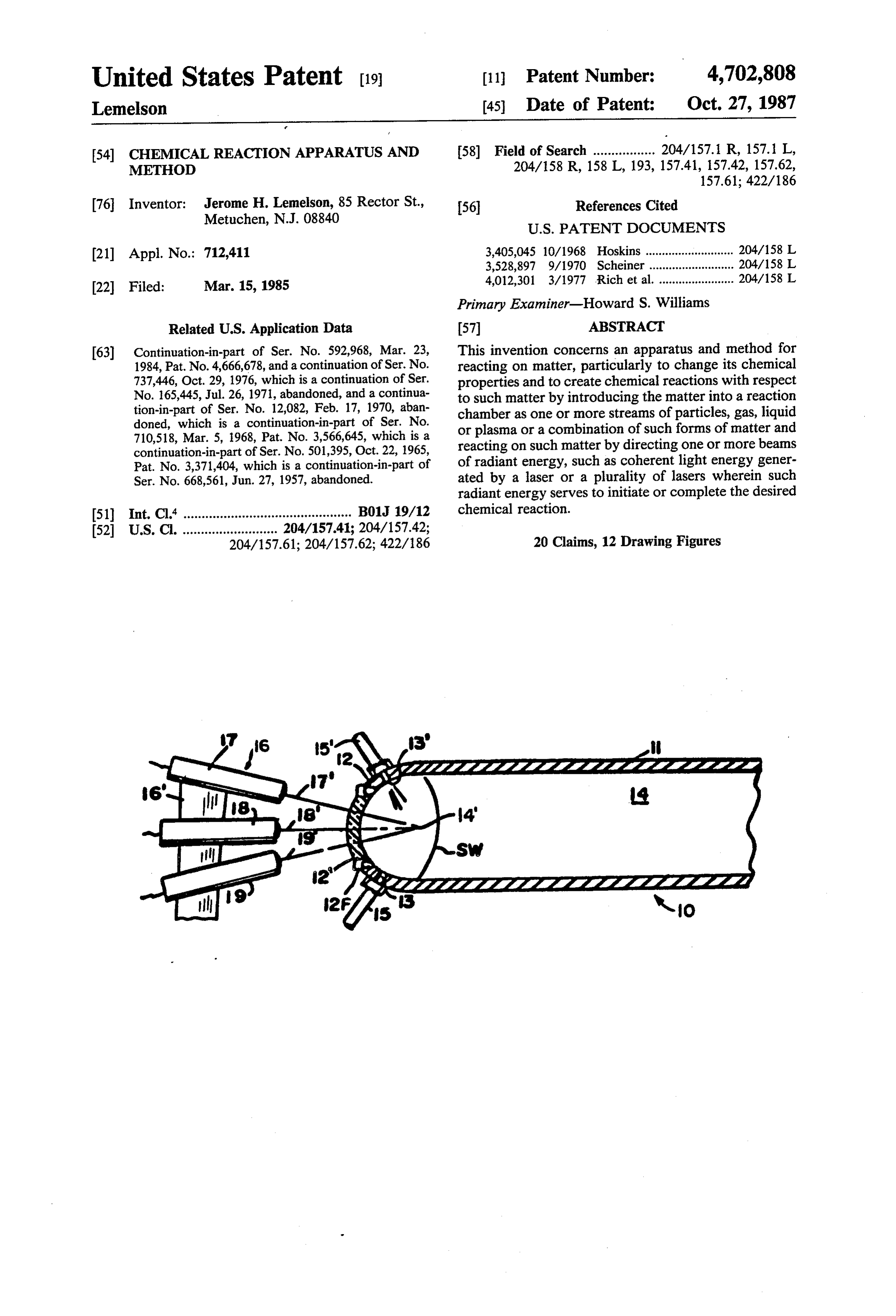
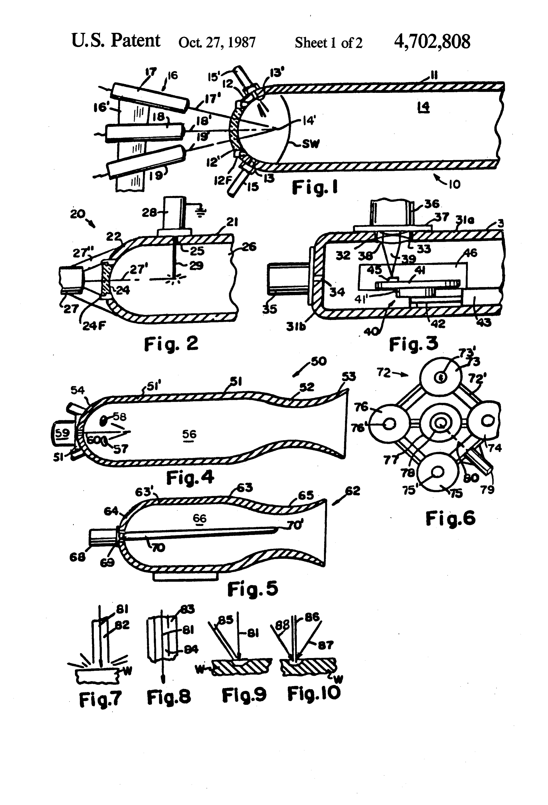
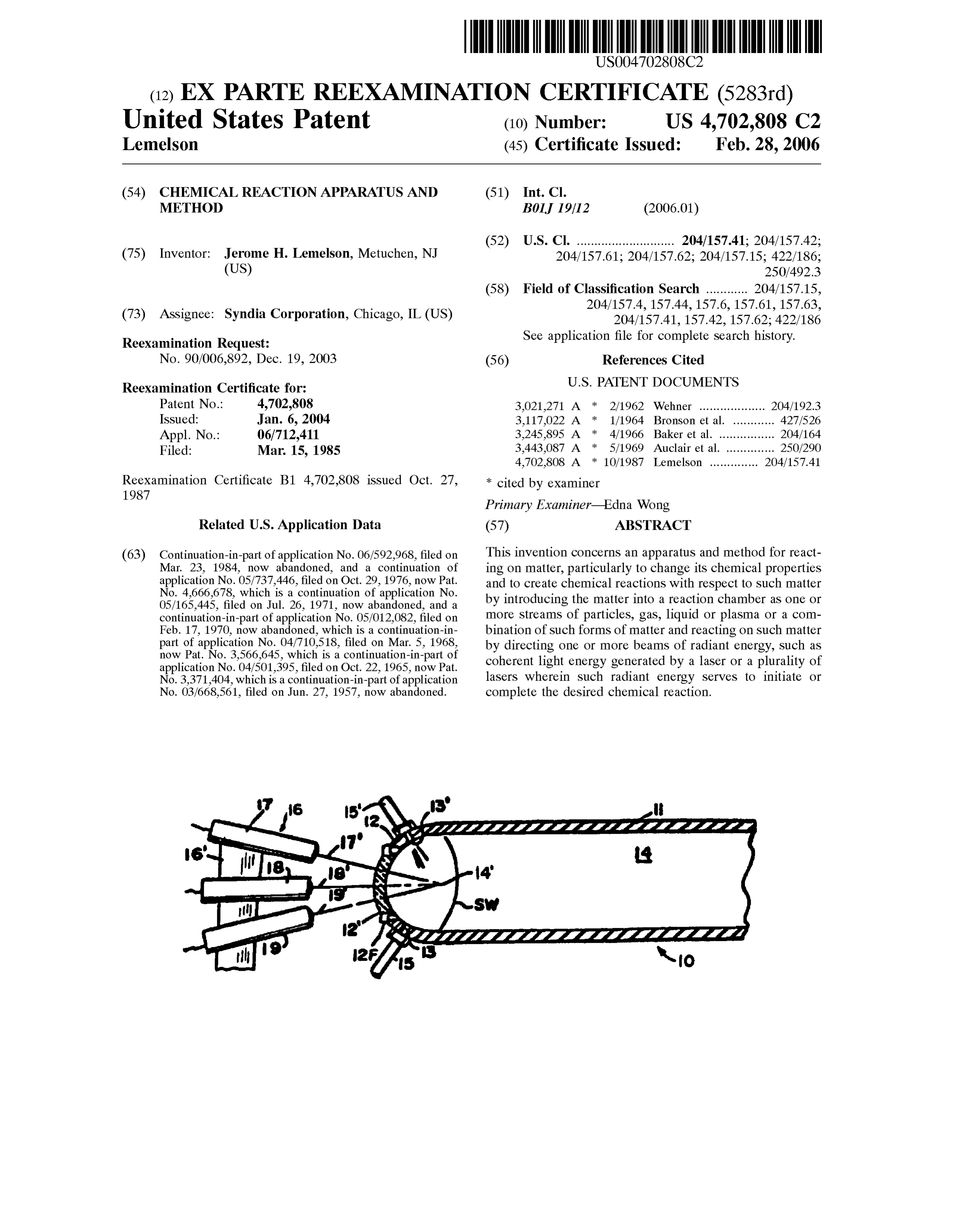
such matter, is controlled in its generation by a master ber. One or all the beams may also be directed through controller or a computer. small openings in the wall of the chamber, which may With the above and such other objects in view as may be two to one hundred times the diameter of the beam hereinafter more fully appear, the invention consists of and may replace the transparent window. In the illus the novel systems and methods as will be more fully 5 trated embodiment, the energy generated by each beam described and illustrated in the accompanying drawings in heating the portion of the window through which it but it is understood that changes and modifications may passes, is not sufficient to damage said window but the be resorted to which fall within the scope of the inven concentration of radiant energy from the plural beams tion as claimed. at the working region or focal point 14 may be utilized In the drawings: O to generate substanially higher temperatures in the FIG. 1 is a side view with parts broken away and working zone than would be generated by a single work sectioned for clarity of a reaction apparatus showing at processing beam which may necessarily be of such an least a portion of a reaction chamber thereof and means intensity to destroy or damage the window 12'. situated outside of the reaction chamber for generating Where used herein, the term window may be con high temperatures and pressures including shock waves 15 strued to mean a transparent insert in the chamber wall within the reaction chamber; or a small opening extending through the chamber wall FIG. 2 is a side view with parts broken away and through which the laser light beam or other form of sectioned for clarity of a modified form of the apparatus radiant energy may pass to the interior of the chamber. of the type shown in FIG. 1; Thus with an arrangement of the type shown in FIG. FIG. 3 is a side cross sectional view of a reaction 20 1 whereby a plurality of intense radiant energy beams chamber and means for movably supporting work are directed through respective different portions of a therein to receive radiant energy from an external window and are converged to a focal volume, substan Source; tially higher temperatures may be provided at a reaction FIG. 4 is a cross sectional view of a rocket engine having externally supported means for initiating and 25 zone than of a reaction chamber by means of radiant energy would be possible by utilizing a single beam of sustaining combustion within the chamber; coherent laser light.
FIG. 5 is a side cross sectional view of another form of rocket motor employing externally mounted, radiant to The arrangement illustrated in FIG.1 may be utilized perform a number of different operations on matter energy generating means for igniting the rocket fuel;
FIG. 6 is an end view of a plurality of reaction cham 30 disposed within the reaction chamber. In the arrange ment illustrated in FIG. 1, the reaction chamber 11 is bers and an externally mounted means for selectively employed as a shock tube in which one or a plurality of directing radiant energy into said chambers; shock waves are generated by means of intense radiant FIG. 7 is a partial side view of a radiant energy beam energy directed into the tube, as described, and travel transmitted through a fluid stream and applicable to the down the tube to react on matter therein or matter
disposed beyond the far end of the tube. Certain of the
FIG. 8 is a partial side view of a radiant energy bean operations transmitted through a tubular fluid stream; which may be performed by such a shock FIG. 9 is a view of a radiant energy beam and associ tube are described in application Ser. Nos. 668,561 now ated fluid stream cooperating jet operating on a work abandoned and 501,393 now U.S. Pat. No. 3,371,404. piece; 40 If the lasers 17, 18 and 19 are simultaneously acti FIG. 10 is a side view of a beam of radiant energy and vated whereby each generates an intense pulse of light a fluid stream intersecting a work piece and applicable energy in phase with each other, intense heating of to the apparatus of this invention. matter in the focal volume 4' will be effected near the FIG. 11 is a side view with parts sectioned of a modi head end of the chamber and gas or liquid molecules fied form of reaction apparatus and control means 45 disposed within such focal volume will be rapidly therefore and heated and expand rapidly outwardly therefrom to form FIG. 12 shows a valving arrangement applicable to a shock wave SW, a portion of which shock wave will the apparatus of FIG. 11. immediately travel down the reaction chamber while There is shown in FIG. 1 a reaction apparatus 10 the remaining portion of the shock wave will reflect off operative for performing various operations on work 50 the side and end wall of the chamber and will also travel in-progress and having an elongated reaction chamber down the chamber react on fluid therein. Working and 11, which may also be spherical, with a head-end 12 at /or driving fluid or other fluent material may be in least a portion 12 of which is made of a light transmit jected through or near the head end 12 of the chamber, ting material, such as high temperature glass, quartz or either continuously or intermittently in phase with the transparent ceramic having the ability to withstand high 55 operation of the lasers to produce select results or reac temperatures and pressures. The entire reaction cham tions. Notations 15 and 15 refer to inlet ducts which are ber may also be made of or lined with a high tempera respectively connected to openings 13 and 13" in the end ture ceramic material such as Pyroceram manufactured wall 2 of the reaction chamber 11. Fluent material by the Corning Glass Works of Corning, N.Y. Disposed introduced therethrough as well as through other por externally of the reaction chamber 1 on a mount sup 60 tions (not shown) of the wall of the reaction chamber, ported preferably by the means supporting the cham may be utilized to serve as the medium in which the ber, are shown a plurality of radiant energy beam gener shock waves are generated and/or to be reacted on by ating devices 17.18 and 19, such as electron guns or the shock waves directed therethrough. Gas, vapor, lasers adapted to generate respective beams 17,18' and particulate material or solid material may be introduced 19' of intense coherent light energy, which are directed 65 through one or more inlets to the reaction chamber 11 through different portions of the window 12' and aimed at a predetermined rate of flow to effect predetermined to converge on a defined small volume 14 within the chemical reactions for analysis or the production of new chamber or to intersect at a point 14 within the cham compounds, as described in said application Ser. Nos.
Page 6
668,561 (abandoned) and 501,395 (now U.S. Pat. No. become vacuum metallized when the metal vapor, such 3,371,404). as aluminum, is formed by the action of the beam, and The reaction apparatus 10 illustrated in FIG. 1 may flows to the surface of the object. A feeding device 28 also be utilized to generate a reaction force. For exam for the wire 29 is situated exterior of the chamber 21 and ple, if a gaseous or vaporous fuel is injected through the 5 feeds the wire 29 through an opening 25 in the wall of inlet lines 15 and 15", it may be rapidly expanded and 21 at a controlled speed. The wire may be positively exploded within the reaction chamber to cause the de electrically charged to effect suitable flow of the vapor vice to be operative as an intermittent rocket or pulse to the articles to be coated, which may be negatively jet. If a piston is disposed within the reaction chamber charged. The device 28 contains a coil supply of such and is free to slide back and forth therein, the rapid O wire and a servo motor for predeterminately feeding heating and, explosion and expansion of gases injected same to the beam 27 passed through window 24. Pro into the volume 14 may be utilized to drive the piston to vided, but not shown in FIG. 2, is a suitable means for either directly perform work or indirectly. The cham evacuating air from the interior of chamber 21, when ber 11 may thus be one of a plurality of cylinders form necessary, to effect vacuum metallizing or other pro ing part of an internal combustion engine of conven 15 duction functions employing material evaporated from tional piston-cylinder arrangement which is operative the wire or rod 29 fed to the beam. to drive a shaft or other suitable mechanical means. The The device 20 of FIG. 2 may also be utilized as a hot expanding gases generated by the direct rapid heat source of vaporous metals or other materials for use in ing thereof by the laser beams or the explosion of com plasma apparatus such as a magneto hydrodynamic bustible mixtures within the reaction chamber 14 may 20 generators Accordingly, suitable means may be pro also be employed to operate a turbine or other high vided for predeterminately conveying or otherwise temperature engine. The heat and pressures generated removing the vaporous material from the chamber 21 to by the shock waves or explosions resulting from direct provide same at the volume where it is to be utilized. ing the intense radiant energy beams through the win In FIG. 3 is shown a modified form of high tempera dow 12' may also be utilized to effect physical as well as 25 ture apparatus 30 including a reaction chamber 31 defin chemical changes in matter such as the shock wave or ing a totally enclosed internal volume 31V in which is explosion bonding of two or more sheets of metal to disposed a manipulation apparatus 40 for one or more gether, the cladding of two sheets together or the secur units of work 45 to be operated on by an intense radia ing of a particulate material disposed in the surface of tion bean directed into the volume 31V from an exter the sheet placed on the path of the shock waves, or the 30 nal source of energy supported in a housing 36. An forming of one or more sheets against a die aligned with opening 32 in the side wall 31a of the housing 31 has a the far end of the reaction chanmber 11, as described in frame or mount 33 for a focusing lens 38 which is seal said parent applications. The apparatus of FIG. 1 may ingly secured therein in alignment with the output of a also be utilized to effect chemical reactions involving source of intense light energy provided in a housing 36, one or more gases or fluent materials disposed within 35 the flange of which lens is secured and sealed to the side the volume 14 surrounded by the chamber. It is noted wall 31a, Light from the source within housing 36 is that the fixture 16 on which the multiple lasers 17, 18 directed through the lens 38 and focused on a work and 19 are mounted, may contain means for adjusting or piece 45 which is mounted on a rotatable base 41 sup predeterminately varying the attitude of one or more of ported on a mount 41'. A program controlled motor the lasers and may include means for adjustably mount 40 (not shown) is employed for predeterminately rotating ing or supporting the combustion chamber 11 with said base to predeterminately locate one or more work respect to the lasers to permit the location of the focal pieces on the table 41 with respect to the focal point of volume 14 to be adjustably changed or varied during a light 39 passed through the lens 38. The base 41' is cycle of operations. If the apparatus of FIG. 1 is used to secured to arm 42 which is the shaft of a lineal actuator effect the welding of a work piece disposed within a 45 43 which is also automatically controlled to move the chamber 11, then a plurality of lasers may be individu assembly supporting the work in parallel to the side ally varied in attitude by respective servo motors con wall 31a such that substantially any location on the trolled by control signals from a master controller, such upper surface of the work 45 may be intersected by the as a computer, to direct the respective beams of intense focusing light energy for scanning same such as in the coherent light to permit them to simultaneously interact 50 act of welding or inspecting said surface. Further means the same or different areas of the work piece for per (not shown) may be provided for either moving the base forming the same or different welding or other opera 41" in a direction towards and away from the housing 36 tions on the work disposed within the chamber. to vary the location of the focal or intersecting point of In FIG. 2 is shown a modified form of reaction cham the beam 39 in direction above the table 41. ber apparatus 20 employing a totally enclosed reaction 55 Notation 35 refers to a vacuum pump secured to the chamber 21 having a head end 22 containing an opening end wall 31b of housing 31 which communicates 23 therein in which is disposed a window 24 of the type through an opening 34 in said end wall with the interior described, through which window a light beam 27" is volume 31V for removing atmospheric air therefrom. directed from a source 27, such as a laser. A light beam The apparatus 30 also includes one or more doors 46 for 27" is shown intersecting a wire element 29 disposed 60 the admission and removal of work and may include within the volume 26 surrounded by the reaction cham conveying means (not shown) operative to transport ber and is operative to vaporize said wire to provide work to and from the interior volume 31V prior to and metal vapor within the chamber volume 26. Accord after it has been processed as described. ingly, the apparatus 20 may perform one or more of a The operation of the light source in housing 36, varia plurality of functions involving the use of a vaporized 65 tion in its intensity and location of its focal point within metal or other material. For example, the reaction the chamber 31V, and means for removing air or pro chamber 21 may be part of a vacuum metallizing cham viding an atmosphere within the chamber and the oper ber containing objects (not shown) situated therein to ation of the servos for predeterminately positioning the
Page 7
work on table 41, may all be under the control of a thrust axis thereof so as to locate the laser away from single computer or cycle controller, such as a multi-cir the direct exhaust gases.
cuit timer to effect preprogrammed operations on a FIG. 6 illustrates an apparatus 72 which comprises a work piece disposed within the chamber. plurality of reaction chambers, combustion chambers or The apparatus of FIG. 3 may also be modified to rocket engines defined by notations 73, 74, 75, 76 and include a plurality of windows of the type illustrated 77, shown provided as a cluster of four surrounding an and different sources such as lasers disposed in align internal chamber 77. Such chambers may also comprise ment with respective of said windows for generating piston-containing combustion chambers of an internal and directing respective beams of light energy there combustion engine, such as a gasoline or other fuel through to cooperate in scanning the same or different 10 burning engine, operative to rotate a crank shaft when areas of one or more work pieces disposed within the fuel is burned in the respective chambers in a synchro chamber 31. nous manner to drive respective pistons coupled by FIG. 4 illustrates a liquid rocket motor 50 embodying piston rods to said crank shaft. features of the invention described. The rocket motor The novel essence of the invention defined in FIG. 6 50 is provided with a casing 51 having a side wall 51' 15 comprises a means for using the intense radiation gener which is open at one end 53 and defines an internal ated by one or more lasers to ignite fuel in respective volume 56 in which fuel is burned and rapidly acceler neously or orin acombustion cylinders chambers, either simulta ated rearwardly through the throat section 52 of the laser is preferablyrequired sequence. In FIG. 6, a single supported by a gimball mount and is casing to generate thrust. The head end 54 of the motor casing has a plurality of inlets, two of which, 57 and 58, varied in attitude by means of a servo 79 having an are shown, which are defined by respective fuel nozzles output shaft 80 coupled to said gimball mount permit the direction of the intense light beam of the laser to be mounted thereon and fed by one or more liquid propel selectively directed at each of the cylinders or combus lents or fuel materials, which are ignited by an intense tion chambers radiant energy such as a light beam 60 generated by a 25 such chambers inaresequence.
provided
The end walls of each of with respective openings laser mounted in a housing 59 supported at the front end and light transmitting windows of the casing 51. An opening 61 in the front wall 54 of 73', 74, 75, 76, etc. through whichdefinedintense by notations light energy the rocket casing is either sealed by means of the hous may be selectively directed from the single laser 78 ing 59 or contains a transparent window, which is when properly aimed thereat as the laser is pivotally sealed therein, through which a beam 60 of intense light moved on its mount. Thus, explosions or reactions may energy is directed to the interior volume 56 and caused be intermittently generated by pulsing and light from to intersect fuel fed through the inlets 57 and 58 to effect the laser 78 through the openings or windows in each of the ignition of same. Said fuel may be fed continuously the cylinders in sequence. The cylinders may be ar or as a series of intermittent injections into the interior ranged as in a conventional internal combustion multi volume 56, while the laser beam 60 may be generated 35 cylinder engine or in any other suitable arrangement, continuously or intermittently timed with respect to the such as illustrated, to generate shaft work or thrust or to injection of fuel to provide an optimum burning condi create chemical reactions in each of the cylinders. Bun tion for a constant flow or pulsed rocket. If the inlets 57 dles of optical fibers may also extend from a single laser and 58 respectively provide for the admission of ram air 78 through the walls or the window portions of each of and a combustible fuel, the device 50 may be operative the cylinders 73 to 77 to simultaneously transmit light as a ramjet or pulse jet with the laser device in housing energy to each for the purposes described. A mechani 59 operative to sustain combustion or effect the inter cal or electrical light distribution device coupled be mittent explosion of the combustible mixture to provide tween the output of the laser and the respective fiber thrust. optic bundles may be utilized for channeling each pulse FIG. 5 illustrates a modified form of rocket 62 which 45 or group of pulses generated at the output of the laser to may be a liquid or solid propellent rocket having a respective of the cylinders in a desired sequence. casing 63 defined by a side wall 63, an end wall 64, and In lieu of pivotally moving the housing for the laser a throat section 65 near the open end of the rocket. as described to control the direction of the laser beam, Mounted in a housing 68 against the end wall 64 is a it is noted that an electrical deflection means, or an laser, the output light energy of which is directed along SO optical device such as a mirror or prism mounted within a fiber optic bundle situated in a casing 70 which ex the housing, may be pivoted or otherwie driven and tends axially through the combustion chamber 66 to a utilized to deflection control the beam to cause it to point near the exit end of the rocket. When ignition of scan respective of the cylinder windows or optical fiber the solid propellent is desired, the laser 68 is suddenly bundles extending thereto.
energised, generating an intense pulse of light which is 55 FIGS. 7-10 illustrate a number of beam transmitting transmitted along the fibers of the bundle in casing or and fluid flow arrangements employing cooling fluids tube 70 to the end 70' thereof from which the light exits and intense radiant energy beams which are applicable and is operative to ignite propellent immediately in to the apparatus herein described. In FIG. 7 is shown an front of the end of the bundle after which combustion intense radiant energy beam 81, such as that generated continues by conventional burning. Notation 69 refers 60 by a laser and directed along a liquid or fluid stream 82, to a coupling means between the near end of the optical which may comprise a swifty flowing gas or liquid fiber bundle and the output end 70' of the laser in hous which is operative to either shield the beam from the ing 68. It is noted that a fiber optic bundle may also be surrounding atmosphere, transfer heat from work and directed from a laser into the open exit end of the rocket material adjacent the area intersected by the beam and or through the side wall thereof to ignite rocket fuel, 65 /or to cooperate with the beam in performing one or when it is desired to generate thrust. Ignition may also more operations on a work piece. The fluid stream 82 occur as the result of a laser disposed beyond the ex may comprise a high velocity flow of an inert or a haust end of the rocket and preferably located off the reactant gas, which may be operative to chemically or
Page 8
physically react on the material of the substrate inter continuously or intermittently generated simulta sected by the beam 81. Oxygen, for example, will serve neously with the initiation of flow of the fluid stream or to rapidly oxidize the material intersected thereby in the between pulses of fluid stream applied to the work. In beam for cutting or erosion purposes. If the beam 81 is this connection, the beam may be be used to spot weld to be utilized to weld, the gas stream 82 may be an inert 5 or heat treat a selected portion or portions of the sub gas operative to protect the heated and welded portion strate or work and the fluid stream may be used to cool of the work intersected thereby. The swiftly flowing the melted material or to prevent its heat corrosion molecules of the gas stream 82 may also be operable to immediately thereafter.
cause the flow of substrate material which has been III. The described fluid streams may contain abrasive melted by beam 81 away from the area of the substrate 10 particles operable to erode the surface intersected intersected by the beam so as to effect the selective thereby wherein the beam is operated to heat the sur shaping of one or more portions of the work. face abraded by such particles to facilitate the abrading In FIG. 8, a hollow fluid stream 83 is generated to action. If the particles are to be deposited to form a define a gaseous or vaporous interior volume 84 coating on the work piece, they and the work piece may through which volume an intense electron or light en 15 be heated by the beam to facilitate and improve the ergy beam 81 is directed. If intersected against a work coating action.
IV. Two or more streams of two or more fluids such piece which is adapted to be eroded or welded by means of the beam 81, the jacket of inert gas 83 may be as gases or liquids or combinations of such fluids, either operative to protect the area heated by the beam 81 one or both of which contain an intense radiation beam from heat corrosion. 20 directed therealong, may be caused to intersect each FIG. 9 illustrates a machining or erosion arrangement other so as to effect chemical or molecular reactions in which a beam 81 of intense light energy, such as an resulting at least in part from the temperature of the electron or laser beam, is directed against the surface of radiation employed.
a work piece W. The same area the beam intersects is 25 V. Particulate coating or deposition material may be also intersected by a high-velocity gas or liquid jet controllably introduced into the fluid stream(s) and stream 85 which may be operative to cause the flow of melted or vaporized in transit therealong to permit such material, melted by the beam, away from the area inter material to be coated or plated onto the work or sub sected by the beam to cooperate with the beam in cut strate intersected by the stream and/or beam. The sub ting, eroding, welding or otherwise reacting on the strate receiving same may be heated by the beam and work. 30 hot fluid heated by the beam to render same molten or Another arrangement is illustrated in FIG. 10 at a temperature high enough to facilitate or effect coat wherein a plurality of intense radiant energy beam, two ing of the solid particulate or molten material carried by of which 87 and 88 are shown, are generated and fo the beam on the substrate.
cused against a small area of the surface of the work W VI. Work material erosion or machining resulting while a high-velocity stream 86 of gas or liquid fluid or 35 from the fluid-beam arrangements of FIGS. 7 to 10 may particles is directed against substantially the area of the include, in addition to cutting, boring, drilling, con work intersected by the beam. The apparatus of FIG. 11 trolled material removal, deburring, and the softening may be utilized for welding, cutting, erosion, test or of metal to render it easier to be machined by a cutting chemical reaction purposes and the beam, as well as the tool, the movement of material from one location to stream of fluid 86 may be predeterminately controlled 40 another on the substrate by the mechanical force of the in intensity and scanning movement to effect a predeter fluid stream reacting against the softened or molten mined operation on the work. material rendered in such condition by the beam and the The beam and fluid flow arrangements of FIGS. 7-10 heated fluid.
may be applied to any of the herein described apparatus VII. The arrangement shown in FIG. 8 may define a for the purposes of reacting on solid, liquids or gases 45 tubular member (83) of metal or ceramic, along the disposed in a closed or partially closed chamber for interior passageway 84 of which an intense laser beam is chemical processing, inspection, testing and analysis of directed to intersect the work. Vapor of the material of materials, surface erosion, cutting, welding, heat treat the work piece, formed by the intense heat of the beam ing or otherwise processing matter. Applications of the pulsed in the tubular member may be drawn through beam-fluid arrangements shown in FIGS. 7 to 10 may 50 the tube by applying suction thereto and may be ana include, in addition to those shown in FIGS. 1 to 6 lyzed when so drawn off by suitable automatic analysis wherein the fluid stream or streams may be generated means. The pulsing of the beam and the application of exterior and/or interior of the reaction chamber, other vacuum pressure to the tube may be automatically con arrangements as follows: trolled to effect a predetermined sampling and analysis. I. The fluid streams 82,83,85,87 and 88 of FIGS. 7 to 55 Modifications to the apparatus described may include 10 may contain one or more chemicals in gaseous, va the elimination of light transmitting windows in the porous or solid particulate form to be deposited on that wall of the reaction chambers and their replacement area or areas of the surface of the work piece intersected with may small openings in the wall of the chamber which remain open during the operation of the apparatus by the beam and heated or melted in a manner such that the material carried by the fluid stream either combines 60 or may be closed immediately after passage there with, or is molecularly bonded or welded to the sub through of the intense beam or beams of radiant energy. strate upon solidification of the molten material after For example, a small opening in the wall of the reaction the beam has been moved or terminated. chambers of FIGS. 1-3, perhaps two to five times the II. Fluid, such as a gas, may be so heated by the beam diameter of the radiation beam, may replace the illus of intense radiant energy 81 directed therethrough as to 65 trated translucent windows for allowing the passage of effect selected heating, burning, melting, vaporizing, intense laser generated light to pass from the exterior of softening or other operation on the work intersected by the chamber to the interior thereof. Larger diameter such heated fluid stream. The beams 81, 87 or 88 may be openings may be provided if a valve is disposed and
Page 9
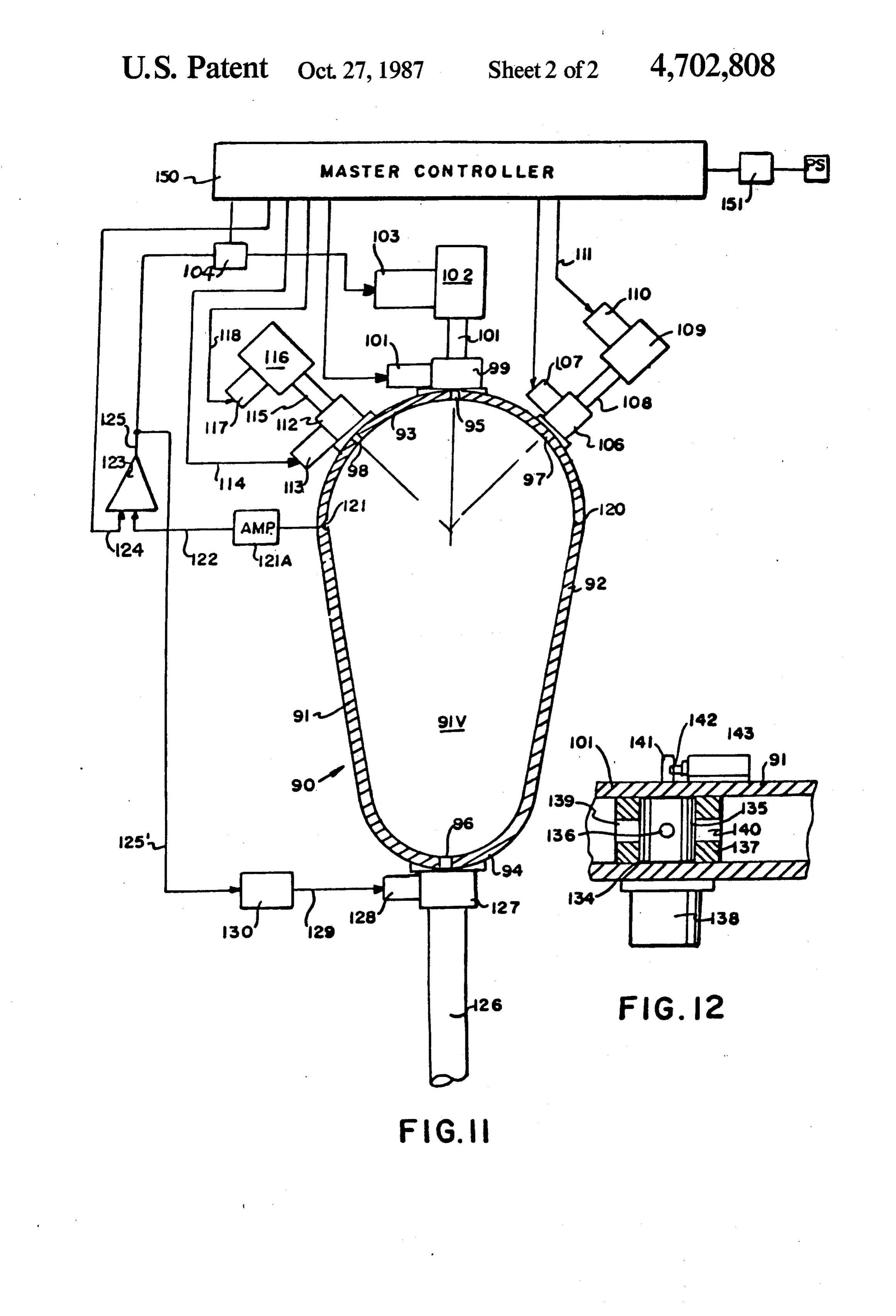
operates to close the opening or passageway leading to be flowed through ducts 108 and 115 and valves 106, thereto immediately after the pulsed beam has passed 112 to the interior 91V of chamber 91, preferably along therethrough. If the opening is employed per se, the predetermined paths or streams of particle or fluid flow atmosphere within the chamber may be controlled by such that it may be detected within the chamber and/or pressurizing same with suitable inert or reaction gas. predeterminately intersected by the beam of intense Vacuum may be retained within the reaction chamber radiation. Notations 110 and 117 refer to respective by controlling the atmosphere within the duct leading motors or other electrically controlled servo devices to the chamber and terminating at the wall portion which may be automatically controlled by signals gen containing the small opening. In certain specialized erated on input lines 111 ad 118 extending thereto from equipment and modes of operation, the reaction cham O the master controller or computer 150. ber may be closed and the intense laser or electron beam While the apparatus 90 may be operated as a rocket may enter said chamber by boring a small hole in the engine or may merely employed to generate and ex wall of the chamber to effect the desired chemical reac haust products of reaction through an open end thereof. tion. The hole may remain to accommodate and pass Shown in FIG. 11 is an an exhaust opening 96 to the subsequently generated pulses of intense radiation or 15 chamber 91 and a valve 127 secured to the end wall 94 may be automatically sealed off by means of a suitable in alignment with opening 96 for controlling the flow of sealant associated with or encapsulated within the products of reaction from the chamber. The valve 127 is chamber wall. A subsequently generated beam may also controlled by a solenoid or motor 128 to open and close be utilized to seal off the opening bored by the previous in accordance with control signals transmitted thereto beam. It is also noted that gas, directed along the beam 20 on a circiut 129 as will be described. as shown in FIGS. 7 and 8, may also be employed to The intense radiation beam generator in housing 102 prevent air or other contaminating material from enter is operated to intermittently generate pulses of radiation ing the small opening in the chamber wall during the by a control 103 which may operate in accordance with operation of the beam. Particles directed along the gas the teachings of my copending applications Ser. Nos. stream and/or beam perse may also be employed to fill 25 856,876 (abandoned) and 12,082 (abandoned) wherein a and close off the hole bored by the beam in the chamber radiation beam of the desired intensity is generated wall. thereby and directed along tube 101 through open valve FIG. 11 illustrates further details of the instant inven 99 and into chamber volume 91V in response to a trig tion including means for controlling the admission of ger signal generated on the input 104 to the beam gener material to a reaction chamber such as a chemical reac 30 ator trigger control 103. The trigger pulse may be gen tor or rocket engine and the generation of intense radia erated either as a direct output signal of the master tion for predeterminately reacting on the material ad controller or computer 150 or by means of logical cir mitted to perform one or more of the described func cuitry to be described depending on the mode of opera tions of heating, causing chemical changes therein, gen tion desired and the particular reaction parameters. In erating thrust or gas at high pressure: Control means are 35 FIG. 11, a double throw switch 104 may be manually provided in FIG. 11 which may be applied to the here operated to connect the input 104 to the beam generator inabove described embodiments with obvious modifica trigger control 103 either directly to an output of master tions without departing from the nature of the inven controller 150 or logical switching means 123 to be tion. described.
In FIG. 11, a reaction apparatus 90 includes a reac 40 If the beam operated reaction occurring within cham tion chamber 91 having a suitable side wall 92 and end ber 91 is of such a nature that timing control means may wall portions 93 and 94 preferably of spherical or bul be employed to control the admission of material to the bous configuration and made of a suitable high tempera reaction zone of the chamber and the operation of the ture, high strength metal, metal laminate or filament beam generator, and removal of reaction material, then wound composite such as boron, boron nitride, boron 45 master controller 150 may comprise a multi-circuit self carbide or other high strength filament reinforced recycling timer or open loop computer. However, if it is metal, metal alloy, ceramic or carbon material capable desired to fire the laser or electron gun to cause the of withstanding high temperature and pressure. A small beam to predeterminately react on a quantity of matter window or opening 95 is provided in the end wall 93 injected into the chamber, and variations may occur in thru which an intense radiation beam by be directed 50 the operation of the system, then the material injected from a beam generator such as a laser or electron gun thru either or both the inlets 97 and 98 may be sensed 102 located in a housing 102. The beam is directed and detected by a device such as a photoelectric or along a tube 101 thru a valve 99 which is aligned with infra-red detector 121 disposed in the wall of the cham opening 95 and secured to the end wall 93. The valve 99 ber. Such detector 12 may be operative to generate a is operated by a solenoid or motor 100 to open and close 55 detection signal on its output 122 which is amplified in intermittently under the control of a master controller amplifier 121A and is applied to one input of a logical 150 which generates control signals in sequence to con AND switching circuit 123, the other input to which trol the variables of material admission beam generation has been energized by a signal generated by master and, if necessary, material exhaust or flow from the controller 150 when both the inputs of circuit 123 are chamber when a start-switch 151 is closed. 60 simultaneously energized. A signal is generated on out Secured in alignment with a plurality of openings 97 put 125 of the AND circuit which is transmitted to and 98 in the chamber wall adjacent the window or activate the beam generating trigger circuit 103 of the opening window 95 are respective valves 106 and 112 laser 102. The valve 99, through which the laser beam is which are operated by respective solenoids or motors passed into volume 91V, may either have been opened 107 and 113 which are also controlled in operation by 65 by a signal generated by master controller 150 and ap signals generated by master controller 150. Inlet ducts plied to the valve servo or solenoid 100. The valve 108 and 115 extend from respective reserviors 109 and solenoid 100 may be pulsed to open by a reproduction 115 of liquid, gaseous, particulate or vaporous material of the signal generated on the output 125 of AND cir
Page 10
cuit 123. The characteristics of the valve 99 are such While one laser 102 is shown in FIG. 1, a plurality of that it will remain open after being opened for a suffi suitable lasers may be mounted around the chamber 91 cient time interval to allow the pulse of radiant energy each being operable to generate and direct a beam of generated by laser 102 to pass therethru before it closes coherent radiation through a respective window in the immediately after the passage of the beam there chamber wall. An advantage of using such a laser beam through. generating system for effecting a chemical reaction or The output signal of AND circuit 123 is also passed the combustion of fuel, is that the energy of the beam to a delay relay or delay line 130 which is preferably will react on and be transferred to the fluid or fluids adjustable to cause it to generate a control signl for through which the beam passes along the length of the pulsing a solenoid 128 for operating an exhaust valve 10 beam passing there through, thus providing an extended 127 disposed between chamber volume 91V and ex path along which reaction or combustion takes place haust line 126 for allowing the products of reaction to whenever the beam is generated and so directed. controllably escape or be exhausted from the chamber. Notation 102 may also refer to other means for gener The valve 127 may also be eliminated for those applica 5 ating or providing collimated radiation for effecting tions where it is desired to cyclically exhaust material chemcial reactions and initiating combustion such as an from the chamber immediately after and as a result of electron gun, a molecular bean generator, a source of the direct pressure increase caused by the intense radia neutron radiation including cold neutron radiation, a tion of the beam and/or the resulting explosive reaction. source of gama radiation, a particle accelerator or a Valve 127 is used where it is desired to increase pressure plurality of same.
and retain reaction material in the chamber for a select 20 Additional forms of the invention are noted as fol time interval after one or more pulses of radiation and lows:
one or more quantities of reaction material having been 1. The apparatus 10 of FIG. 1 may be employed for injected into the chamber. the purpose of generating thrust in pulsed manner, for In FIG. 12 is shown further means for controlling the propulsion purposes, such as in a pulse jet or pulse operation of the radiation beam generating means in 25 rocket. In addition to creating chemical reactions in accordance with the operation of a high speed valve volving the shock waves SW generated in the gas col wherein valve, operation controls the pulsing of a laser umn 14, the combined radiation effect of the several or or electron gun. The valve 134 of FIG. 12 is a rotating more beams 17, 18' and 19 which are directed to inter cylinder 135 disposed in a seat 137 located between duct sect a focal area or working region may also be em 101 and chamber 91 and rotated by means of a speed 30 ployed to heat and weld, machine by vaporization or controlled motor 138 to align a small hole 136 extending otherwise finish an article or surface disposed in region diametrically thru the cylinder 135 with respective inlet 14, or effect a chemical reaction or reactions with re and outlet holes 139, 140 in the valve seat. When such spect to one or more fluid chemicals introduced into the alignment is effected during each half revolution of the volume 14 of the chamber 11 as described. The several valve cylinder 137, the laser or electron gun is pulsed by 35 beams 17, 18' and 19" may be generated by a single laser a signal generated by a limit switch 141 which is actu and formed by optically splitting the single beam of the ated by a cam 142 on the shaft 141 supporting cylinder laser into several or more beams of the same or different 135. The limit switch 143, shown mounted exterior of intensities and directing each beam through a different duct 101, may also be a photoelectric cell and control or window or opening to the chamber or through the same proximity switch scanning suitable indicia or magnetic 40 window or opening.
markers on the cylinder or motor shaft 141 to generate 2. The apparatus of FIG. 2 may be combined with pulses during each half revolution of thereof which that of FIG. 3 utilizing a single laser or a plurality of pulses are passed to the trigger control 103 of the laser lasers to both vaporize metal within an enclosed cham or electron gun in housing 102 and may also be applied ber and to cause such vaporour metal to become selec to open valves 106 and 112 by pulsing their solenoids or 45 tively deposited on a substrate or substrates, such as pump actuating means for admitting charges of one or microelectronic circuit chips or the like disposed on the more reaction materials from reservoirs 109 and 116. conveyor or platform 41 of FIG. 3 for fabricating mi The master controller 150 may comprise a solid state croelectronic circuits. Such vaporized metal(s) may be programmable electronic controller or computer fabri caused to selectively deposit on the circuit substrate by cated of microelectronic circuitry with either a fixed or 50 means of the focused laser beam or electron beam 39 or a variably programmable memory or memories which a plurality of same.
are programmed to optimize the particular reaction or 3. An internal combustion engine employing multiple reactions which take place in the volume 91V by gener cylinders and pistons or other means for converting ating control signals for controlling fuel and/or reac combustion energy into work in the manner effected by tion fluid flow and laser operation for igniting or pro 55 a conventional gasoline piston engine, may have fuel viding radiant energy for the purpose described. ignited in each cylinder by means of laser light directed The apparatus 90 may be employed perse or in com through respective optical fiber bundles from a single bination with one or more other devices or systems for laser, such as CO2 laser to each cylinder wherein the effecting such functions as the generation of heat for fiber optic cable extends to the cylinder wall and termi direct or indirect conversion to electrical energy and 60 nates against or within an opening in such a wall or a /or the performance of work, a chemical reaction per window disposed therein to permit the intense light to se, the incinerations of a waste material or a combina be passed as a beam into the combustion chambers for tion of such functions. Suitable heat transfer means, igniting fuel therein. An optical component, such as a such as a water jacket or the like, may be disposed mirror or prism, may be operable to deflect or reflect around the wall 92 of the chamber for cooling same and 65 light from the output of the laser to each of the fiber for transferring the heat of reaction to heat transfer optic bundles, one at a time and in a given sequence and apparatus such as a stream generator for operating a timed such that ignition of combustible fuel charges in steam turbine or cogeneration system. each cylinder will occur to properly operate the engine
Page 11
at a desired efficiency. Such mirror or prism may be caused to scan and/or rapidly pulse for effecting com controlled in rotation or deflection to properly direct bustion or reactions at different closely spaced or dis the pulsed output energy of the single laser into the tant locations within the chamber 91 during each cycle selected cylinders or combustion chambers wherein of operation as the fuel or reactants are continuously or such rotation or deflection may be timed to occur in intermittently introduced. Since the laser beam itself synchronication with the driveshaft of a rotation of a does not diminish very much in intensity as it passes shaft such as the gasoline or other fuel engine. through the reaction chamber or chambers, if a reaction 4. In the apparatus illustrated in FIG. 11, notations chemical or fuel is caused to flow through or fill a sub 109 and 116 may refer to respective lasers, electron guns stantial portion of the chamber volume 91V, reaction or or other type of high energy collimated beam energy O ignition will occur along the length or path of the beam generating devices operable to direct their beams at a within the portion of the chamber containing the fuel or point or focal area within the chamber 91, either contin reactant(s), thus providing an improved reaction pro uously as a stream offluent matter is directed from inlet cess. A plurality of intense collimated laser beams will 95 from a supply 103 thereof fed by means of a blower thus initiate ignition or effect a reaction along the path or pump 102, or intermittently to simultaneously or 15 the beam travel through the fuel or reaction chemicals. sequentially intersect matter at such focal area as such 7. In a particular form of the invention, one or more matter is intermittently fed through the opening or lasers may be controlled to rapidly pulse in synchroni valve 95. zation with the operation of a beam deflection control 5. In FIG. 11 a single continuous or intermittently means, to provide one or more pulses of intense radia generated laser, electron or molecular beam passed 20 tion directed at different respective locations or along through opening 95 in the wall of chamber 91, may be different paths within the reaction or combustion cham controlled and directed to intersect one or more of the ber. If the combined pulsing and beam deflection occurs streams of matter introduced through the openings 97 rapidly, say hundreds of times per minute or per second, and 98 in the chamber wall for predeterminately react since each pulse or group of pulses travel a different ing thereon and creating physical and/or chemical 25 path, a substantial portion of the volume within the changes in the molecules or particles defining such reaction chamber may be scanned and heated or irradi steams of matter. Such streams of matter may be in ated by the multiple pulses directed along different gaseous, vaporous, plasma or solid particle form or select paths through the chamber, thus providing rapid combinations of same. The two streams may be formed and more complete reaction or combustion phenomena. of the same matter or combinations of matter or differ 30 8. One or more mirrors or reflecting surfaces dis ent matter and caused to chemically react or combine, posed at fixed locations within the combustion or reac such as in alloying, at or beyond the location where tion chamber may be employed to cause a single beam they intersect and/or are reacted on by the beam or or a plurality of beams directed into the chamber beams of radiation directed thereagainst. In other thereat to reflect therefrom and be directed along the words, two or more streams of matter may be caused to 35 same or different paths through the chamber to permit intersect within the chamber 91 and react when they the beam energy to react on different molecules of fuel intersect as the molecules or particles thereof are heated or reactants existing along the different paths of the or irradiated by two or beams of intense radiation of the beam or beans to effect more complete and more rapid type described, whereafter the products of such reac reactions and/or combustion.
tion or reactions that occur in the chamber are continu 40 9. In addition to employing lasers and electron guns ously or intermittently removed from the chamber as for generating and directing the collimated beans of described. The entire continuous or intermittent flow of radiation for use as described above, other sources of fluid(s) or particles and operationn of the one or more suitable collimated radiation, such as sources of molecu radiation beam generators is controlled automatically lar beam, conventional and cold neutron energy may by a single master controller or computer 150 as de 45 also be employed per se or in selected combinations scribed. thereof.
6. The intense radiation beams generated by the lasers In a particular mode of operation of the apparatus or electron gun means described above may be subject described above, finely devided solid particles of a first to one or more of the following modes of operation to element or chemical are introduced into a gas, vapor or enhance or improve the operations described. For ex 50 plasma stream directed into a reaction shamber of the ample, conventional means, such as a servo operated or type shown in FIG. 11 and a laser beam is generated vibration imparting means may be employed to deflect either continuously or intermittently and directed to a mirror or mirrors receiving laser generated radiation intersect the stream of particles and operated in a man for controllably causing the beam to scan a select voi ner to effect a chemical reaction between the material of ume within the combustion chambers 11,21,51 or 91 55 the particles and the material of the fluid stream. In one while the beam is continuously generated during such form, the particle material is vaporized to effect the scanning or is rapidly pulsed to caue combustion or reaction with the fluid stream material. In another form reactions to occur at a plurality of locations within the two or more materials in solid particle form are intro combustion chamber or zone therein. In FIG. 1 the duced into a stream of such fluid which is thereafter three beams 7,18' and 19' may be synchronously 60 intersected by the described laser beam or beams, scanned and/or rapidly pulsed to rapidly effect combus wherein either or both the solid materials are vaporized tion or reaction at a plurality of locations in the gas and caused to react with each other and/or the fluid column 14. In FIG.2 the bem 27 may be caused to scan chemical defining the particle carrying stream. One or a portion of the end of the rod or wire 29 to better more particulate materials may also be melted in the vaporize same. In FIG. 3 the beam 39 may be computer 65 stream by the action of the laser radiation and deposited controlled in its focus and/or deflection to cause it to on a select area of a substrate to form a coating thereon, variably vaporize or otherwise affect the surface of the - a component of a microminiature electrical circuit or to work. In FIG. 11 the beam or beams described may be effect welding of the substrate or two components
Page 12
which receive the molten particles. Such deposition said second means to cause it to generate pulses of co may be accompanied by a chemical reaction between herent beam radiation which are intermittently directed the fluid of the stream and either or both the molten to intersect said stream of said first matter, said master particles or material of the substrate on which the parti control means being operable to control the timing of cles are deposited. In addition to depositing, the opera 5 the radiation pulses generated during the operation of tion may include machining or eroding material from said second means.
the substrate. 9. Chemical reaction apparatus in accordance with What is claimed is: claim 1 wherein said first means is operable for forming 1. Chemical reaction apparatus comprising in combi and flowing a stream of gas defining at least part of said nation: O first matter.
(a) first means for forming a first stream of first matter 10. Chemical reaction apparatus in accordance with and flowing said first matter in a given direction claim 1 wherein said first means is operable to form said along a selected path, stream of said first matter as a gas or vapor, and dispose (b) second means for generating a beam of collimated particles of solid matter therein to define said first coherent radiation, 15 stream of matter.
(c) third means for directing said collimated radiation 11. Chemical reaction apparatus in accordance with beam along a path to cause it to intersect said claim 1 wherein said first means is operable to intermit stream of matter and to transfer sufficient energy of tently form and direct matter defining said first stream said beam to a quantity of said matter so as to effect along said predetermined path.
a chemical change in said matter, 20 12. A method for creating a chemical reaction com (d) fourth means for controlling the conveyance of prising:
said first matter after it has undergone a reaction as controllably directing a fluid as a stream of fluent a result of the transfer of energy thereto from said material along a select path, which path intersects a radiation beam to carry the products of reaction to reaction zone, so as to present molecules of said a select location. 25 fluent material in a flow thereof through said reac 2. Chemical reaction apparatus in accordance with tion zone, and claim 1 wherein said first means is operable to direct as said fluent material passes through said reaction said beam at an angle to the path said first matter is zone, generating and directing a collimated beam conveyed along. of intense radiation along a path which intersects 3. Chemical reaction apparatus in accordance with 30 said reaction zone such that the radiation of said claim 1 wherein said third means is operable to direct beam passes through said reaction zone while mol said beam in the direction of said first stream and paral ecules of said fluid are present in said reaction zone lel to the path of flow of said first matter. and transferring sufficient radiation from said beam 4. Chemical reaction apparatus in accordance with to said molecules while in said reaction zone to claim 1 including fifth means for forming a second 35 cause said molecules to partake in a chemical reac stream of second matter which is different from said tion while located in said reaction zone. first matter and causing said second stream of second 13. A method in accordance with claim 12 wherein matter to intersect, mix and flow with the first matter in said fluid is continuously flowed at a constant rate of said first stream at a location upstream of the location flow to and through said reaction zone. 14. A method in accordance with claim 13 wherein where said beam intersects said stream of first matter so as to permit said beam to react on the mixture of said said radiation beam is generated for an extended period first and second matter. of time while fluid is flowing through said reaction 5. Chemical reaction apparatus in accordance with ZO. 15. A method in accordance with claim 12 wherein claim 4 including sixth and seventh means for respec tively controlling the operation of said first and fifth 45 said fluid is flowed intermittently to said reaction zone. means to control the flow of said streams of said first 16. A method in accordance with claim 15 wherein and second matter and master control means operable said radiation beam is generated intermittently in a man to selectively control the operation of said sixth and ner to intersect respective quantities of said flow which seventh means in effecting a chemical reaction. are intermittently flowed to said reaction zone. 6. Chemical reaction apparatus in accordance with 50 17. A method for creating a chemical reaction com claim 1 including fifth means for forming a second prising:
stream of second matter which is different from said (a) generating a beam of collimated radiation having first matter and causing said second stream of second sufficient intensity and energy for effecting a chem matter to intersect the stream of said first matter at the ical reaction with respect to matter when said beam location where said beam intersects said first matter so 55 is caused to intersect said matter and directing said as to permit said second matter to combine with said beam along a select path, first matter and to partake in a reaction effected by said (b) controllably flowing a stream of fluent material beam of collimated radiation. containing particles of matter along at least a por 7. Chemical reaction apparatus in accordance with tion of the select path along which said beam is claim 1 including fifth means for controlling the rate of 60 directed, such that radiation of said beam will be flow of said stream of said first matter, sixth means for transferred to particles of said matter during a sub controlling said second means to generate said beam of stantial portion of the travel of said particles along coherent radiation, and master control means connected said select path, and to said fifth and sixth means in a manner to control the (c) causing radiation of said collimated beam to react chemical reaction effected by said beam when it reacts 65 on said particles in said stream as said particles on the matter flowing in said first stream. travel said select path and to change the state of 8. Chemical reaction apparatus in accordance with said particles and cause said particles to partake in claim 7 wherein said sixth means is operable to control a chemical reaction.
Page 13
18. A method in accordance with claim 17 wherein radiation beam is directed against said particles of said said particles are solid particles of matter and said beam Strea.
of collimated radiation serves to vaporize the matter of 20. A method in accordance with claim 17 wherein said particles, further including effecting a chemical said radiation beam is directed through the center of reaction between constituents of said stream of fluent 5 said stream, said beam is deflected to scan within said material including said vaporized material formed of stream and said beam and the fluent material of said said particles.
19. A method in accordance with claim 17, wherein stream are directed against the surface of a solid mate the particles of matter in said stream are formed of rial and are caused to react with at least a portion of said different chemicals and wherein a chemical reaction is 10 solid material.
effected between said different chemicals when said
Page 14
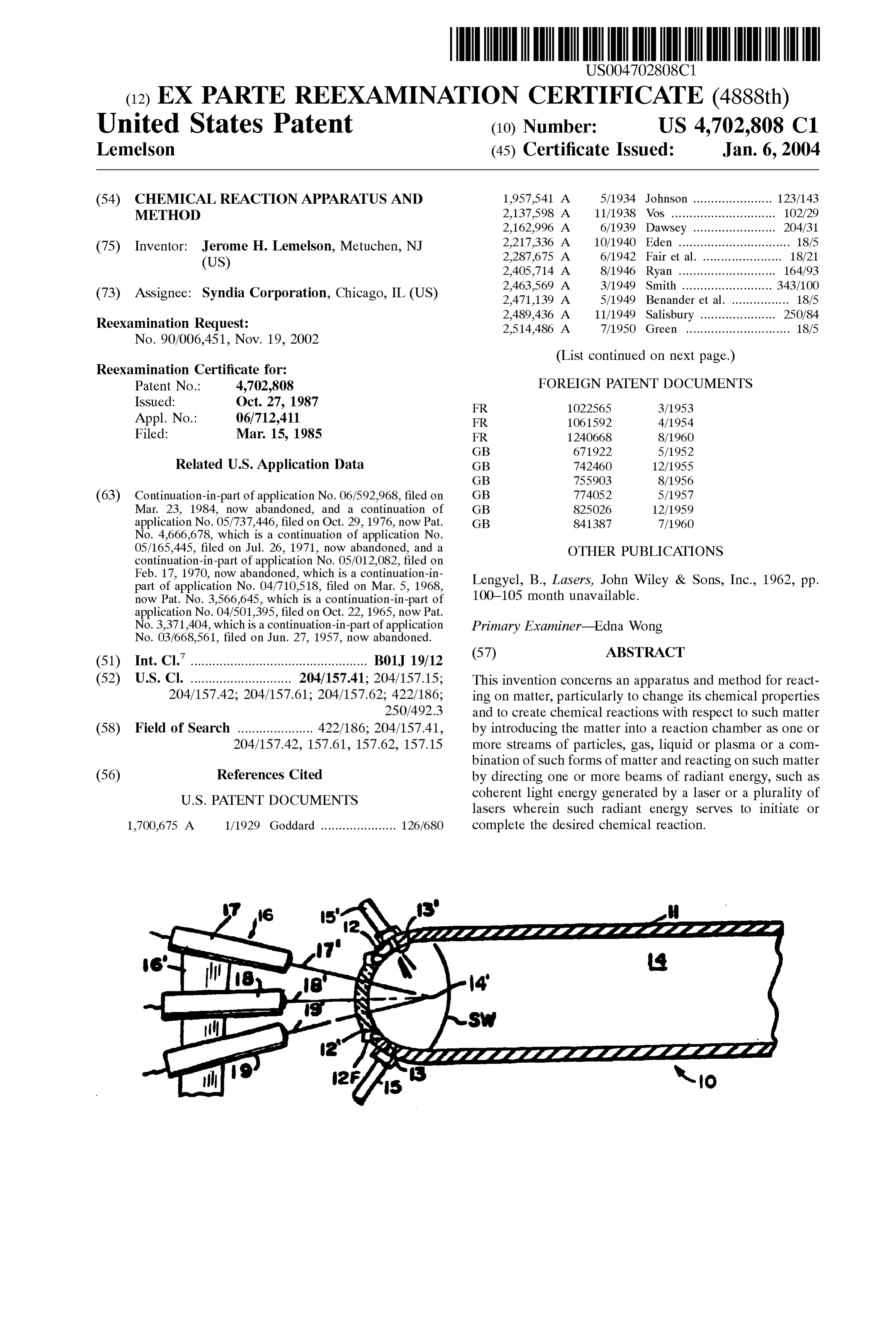
(12) EX PARTE REEXAMINATION CERTIFICATE (4888th)
United States Patent (10) Number: US 4,702,808 C1 Lemelson (45) Certificate Issued: Jan. 6, 2004 (54) CHEMICAL REACTION APPARATUS AND 1957,541 A 5/1934 Johnson ...................... 123/143 METHOD 2,137,598. A 11/1938 Vos ............................. 102/29 2,162.996 A 6/1939 Dawsey ... 204/31 (75) Inventor: Jerome
H. Lemelson, Metuchen, NJ 2,217.336 A
2,405,714. A 8/1946 Ryan ........................... 164/93 rr. A 2,463,569 A 3/1949 Smith ......................... 343/100 (73) Assignee: Syndia Corporation, Chicago, IL (US) 2,471,139 A 5/1949 Benander et al. ................ 18/5 O O 2,489,436 A 11/1949 Salisbury ........ ... 250/84 Reexamination Request: 2,514,486 A 7/1950 Green ............................. 18/5
(List continued on next page.)
Reexamination Certificate for:
Patent No.: 4,702,808 FOREIGN PATENT DOCUMENTS Issued: Oct. 27, 1987 FR 10225.65 3/1953 Appl. No. 06/712,411 FR 1061592 4/1954 Filed: Mar 15, 1985 FR 1240668 8/1960
Related U.S. Application Data GB 742460 12/1955
(63) Continuation-in-part of application No. 06/592.968, filed on GB T74052 5/1957 Mar. 23, 1984, now abandoned, and a continuation of GB 825026 12/1959 application No. 05/737,446, filed on Oct. 29, 1976, now Pat. GB 841,387 7/1960 No. 4,666,678, which is a continuation of application No.
05/165,445, filed on Jul. 26, 1971, now abandoned, and a OTHER PUBLICATIONS continuation-in-part of application No. 05/012,082, filed on
Feb. 17, 1970, now abandoned, which is a continuation-in part of application No. 04/710,518, filed on Mar. 5, 1968, Lengyel, B., Lasers, John Wiley & Sons, Inc., 1962, pp. now Pat. No. 3,566,645, which is a continuation-in-part of 100-105 month unavailable.
No. 3,371,404, which is a continuation-in-part of application Primary Examiner Edna Wong
(51) Int. Cl.................................................. B01J 19/12 (7) ABSTRACT (52) U.S. Cl. ............................ 204/157.41; 204/157.15; This invention concerns an apparatuS and method for react 204/157.42; 204/157.61; 204/157.62; 422/186; ing on matter, particularly to change its chemical properties 250/492.3 and to create chemical reactions with respect to Such matter (58) Field of Search ..................... 422/186; 204/157.41, by introducing the matter into a reaction chamber as one or 204/157.42, 157.61, 157.62, 157.15 more Streams of particles, gas, liquid or plasma or a com bination of Such forms of matter and reacting on Such matter (56) References Cited by directing one or more beams of radiant energy, Such as
lasers wherein Such radiant energy Serves to initiate or 1,700,675 A 1/1929 Goddard ..................... 126/680 complete the desired chemical reaction.
Page 15
3,165,619 A 1/1965 Cohen ........................ 219/121 2,559,227 A 7/1951 Rieber ......................... 128/24 3,177,651 A 4/1965 Lawrence ................... 60/35.3 2,714,563 A 8/1955 Poorman et al. ... 117/105 3,179,783 A 4/1965 Johnson ...... ... 219/76 2,745.861. A 5/1956 Bodine, Jr. ... ... 260/449 3,184,400 A 5/1965 Magnus ... 204/193 2,763,609 A 9/1956 Lewis et al... ... 204/154 3,194,047 A 7/1965 Eggert, Jr. et al. ... 72/349 2,779.279 A 1/1957 Maiwurm ..... ... 102/26 3,197,605 A 7/1965 Sunnen ............. ... 219/76 2,793,282 A 5/1957 Steigerwald .. ... 219/69 3,207,582 A 9/1965 Inoue ... 23/209.1 2,796,734. A 6/1957 Bodine, Jr. ... ... 60/39.77 3,219,792 A 11/1965 Pederson . 219/117 2,796,735 A 6/1957 Bodine, Jr. ...... 60/39.77 3,228.222 A 1/1966 Maier ...... 72/56 2,813,303 A 11/1957 Stevenson et al. ............. 18/20 3.232,085 A 2/1966 Inoue ... 72/56 2,823,419 A 2/1958 Winters et al. .. ... 18/20 3,235.955 A 2/1966 Kunsagi .. ... 29/421 2.837,654 A 6/1958 Berghaus et al. 250/49.5 3.242,339 A 3/1966 Lee .................. 250/203 2.841,687 A 7/1958 Richter ......... ... 219/76 3.244,412 A 4/1966 Robinson et al. . ... 263/40 2.843,542 A 7/1958 Callahan .... ... 204/192 3.271,556 A 9/1966 Harris .............. 219/121 2.844,706 A 7/1958 Lorenz ......... ... 219/69 3.272,347 A 9/1966 Lemelson ... ... 214/1 2.860,251 A 11/1958 Pakswer et al. 250/49.5 3,281,930 A 11/1966 Fordham .... 29/470.1 2,861,166. A 11/1958 Cargill, Jr. .... ... 219/34 3,282,100 A 11/1966 Baker ............ ... 73/190 2.869,825 A 1/1959 Crawford ......... ... 255/1.8 3.289,447 A 12/1966 Amini et al. ..... ... 72/56 2,899,556 A 8/1959 Schopper et al 250/49.5 3,292.253 A 12/1966 Rossner et al. ...... ... 29/421 2.923,852 A 2/1960 Scott et al. ... 31.5/59 3.294,670 A 12/1966 Charschan et al. 204/298 2.939,049 A 5/1960 Blackman .. ... 315/236 3.296,795. A 1/1967 Nielsen ............ ... 60/39.82 2.953,718 A 9/1960 Ducati ........................ 315/163 3,301.993 A 1/1967 Boyd et al. .... ... 219/117 2,958,638 A 11/1960 Tarmy - - - - - - - - - - - - - - - - - - - - - - - - 204/193 3,303,319 A 2/1967 Steigerwald ... 219/121 2.968,723 A 1/1961 Steigerwald .. 250/49.5 3,346,458. A 10/1967 Schmidt ........ 176/1 2.978,569 A 4/1961 Boretti et al. . ... 219/69 3,348.814. A 10/1967 Shaw ...... 259/1 2.984,307 A 5/1961 Barnes .......................... 175/2 3,360,398 A 12/1967 Garbiotti .......... 117/212 2,994,652 A 8/1961 Frazer et al. . ... 204/157 3,364,087 A 1/1968 Solomon et al. .. ... 156/4 3,009,050 A 11/1961 Steigerwald .. ... 219/69 3,369,101 A 2/1968 DiCurcio .... 219/121 3,027,791 A 4/1962 Early et al. ... 83/177 3,378.446 A 4/1968 Whittlesey .. ... 176/1 3,036,374. A 5/1962 Williams ...... ... 29/421 3,389.240 A 6/1968 Sciaky ............. 219/121 3,049,488 A 8/1962 Jackson et al. ... ... 204/312 3,401.249 A 9/1968 Schleich et al. .............. 219/69 3,067,572 A 12/1962 Baumgartner .................. 60/25 3,443,087 A * 5/1969 Robieux et al. ........... 250/41.9 3,089,831. A 5/1963 Kolb ............ ... 204/154.2 3,444,377. A 5/1969 Hora et al. ....... ... 250/84.5 3,094,474 A 6/1963 Gale ....................... 204/193.2 3,450.858 A 6/1969 Pandjiris..... 219/125 3,132,966 A 5/1964 Hughes et al. ........... 117/93.31 3,452,565 A 7/1969 Cadwell ........ ... 72/56 3,133,828 A 5/1964 Slatkin ......... ... 117/93.31 3,485,666. A 12/1969 Sterling et al. ............. 117/230 3,136,882 A 6/1964 Radtke ....................... 219/117 3,156,811 A 11/1964 Barry ......................... 219/121 * cited by examiner
Page 16
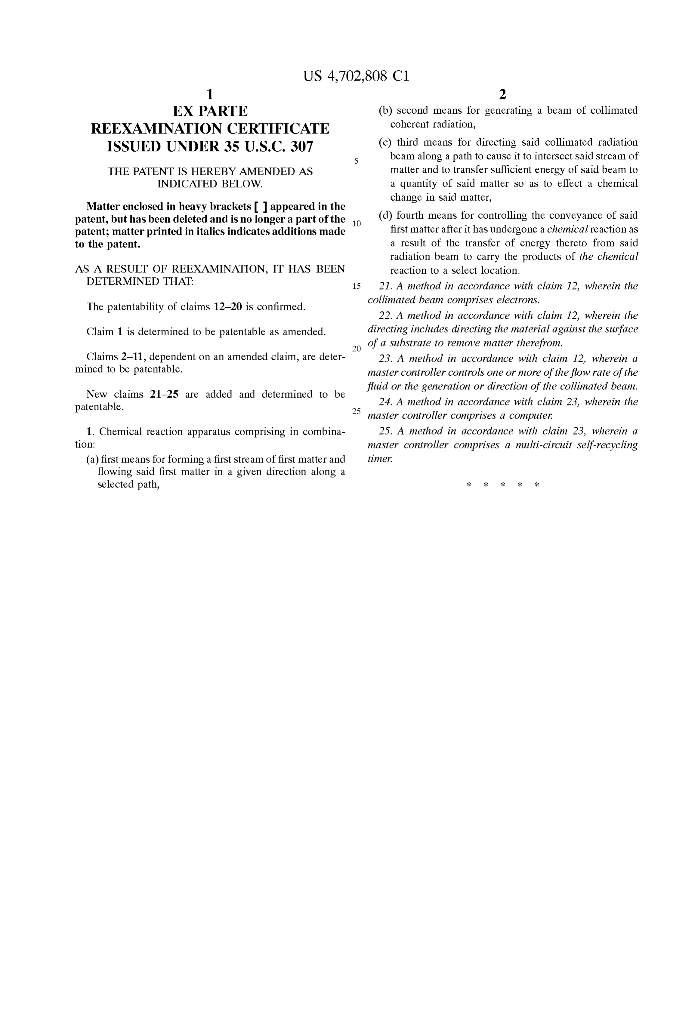
EX PARTE (b) second means for generating a beam of collimated REEXAMINATION CERTIFICATE coherent radiation,
ISSUED UNDER 35 U.S.C. 307 (c) third means for directing said collimated radiation beam along a path to cause it to interSect Said Stream of
THE PATENT IS HEREBY AMENDED AS matter and to transfer Sufficient energy of Said beam to INDICATED BELOW. a quantity of Said matter So as to effect a chemical change in Said matter,
Matter enclosed in heavy brackets appeared in the patent, but has been deleted and is no longer a part of the (d) fourth means for controlling the conveyance of Said patent; matter printed in italics indicates additions made first matter after it has undergone a chemical reaction as to the patent. a result of the transfer of energy thereto from Said radiation beam to carry the products of the chemical
AS A RESULT OF REEXAMINATION, IT HAS BEEN reaction to a Select location. DETERMINED THAT 15 21. A method in accordance with claim 12, wherein the The patentability of claims 12-20 is confirmed. collimated beam comprises electrons. 22. A method in accordance with claim 12, wherein the
Claim 1 is determined to be patentable as amended. directing includes directing the material against the Surface of a Substrate to remove matter therefrom.
Claims 2-11, dependent on an amended claim, are deter 23. A method in accordance with claim 12, wherein a mined to be patentable. master controller controls One or more of the flow rate of the New claims 21-25 are added and determined to be fluid or the generation or direction of the collimated beam.
patentable. 25 24. A method in accordance with claim 23, wherein the master controller comprises a computer:
1. Chemical reaction apparatus comprising in combina 25. A method in accordance with claim 23, wherein a tion: master controller comprises a multi-circuit Self-recycling (a) first means for forming a first stream of first matter and timer.
flowing Said first matter in a given direction along a
Selected path,
Page 17
(12) EX PARTE REEXAMINATION CERTIFICATE (5283rd)
United States Patent (10) Number: US 4,702,808 C2 Lemelson (45) Certificate Issued: Feb. 28, 2006 (54) CHEMICAL REACTION APPARATUS AND (51) Int. Cl.
METHOD BOLI I9/12 (2006.01) (52) U.S. Cl. ............................ 204/157.41; 204/157.42;
(75) Inventor: Jerome H. Lemelson, Metuchen, NJ 204/157.61; 204/157.62; 204/157.15; 422/186; (US) 250/492.3
(73) Assignee: Syndia Corporation, Chicago, IL (US) 204/157.4, 157.44, 157.6, 157.61, 157.63,
Reexamination Request: See application file for complete Search history. No. 90/006,892, Dec. 19, 2003 (56) References Cited Reexamination Certificate for: U.S. PATENT DOCUMENTS Patent No.: 4,702,808 3,021,271. A 2/1962 Wehner ................... 204/192.3 Issued: Jan. 6, 2004 3,117,022 A 1/1964 Bronson et al. ............ 427/526 Appl. No.: 06/712,411 3.245,895 A * 4/1966 Baker et al. ......
Filed: Mar 15, 1985 3,443,087 A 5/1969 Auclair et al. .............. 250/290
4,702,808 A 10/1987 Lemelson .............. 204/157.41
Reexamination Certificate B1 4,702,808 issued Oct. 27, * cited by examiner
Primary Examiner Edna Wong
Related U.S. Application Data (57) ABSTRACT (63) Continuation-in-part of application No. 06/592.968, filed on This invention concerns an apparatus and method for react Mar. 23, 1984, now abandoned, and a continuation of ing on matter, particularly to change its chemical properties application No. 05/737,446, filed on Oct. 29, 1976, now Pat. and to create chemical reactions with respect to Such matter No. 4,666,678, which is a continuation of application No. by introducing the matter into a reaction chamber as one or
continuation-in-part of application No. 05/012,082, filed on more Streams of particles, gas, liquid or plasma or a com Feb. 17, 1970, now abandoned, which is a continuation-in bination of Such forms of matter and reacting on Such matter part of application No. 04/710,518, filed on Mar. 5, 1968, by directing one or more beams of radiant energy, Such as now Pat. No. 3,566,645, which is a continuation-in-part of coherent light energy generated by a laser or a plurality of
No. 3,371,404, which is a continuation-in-part of application lasers wherein Such radiant energy Serves to initiate or No. 03/668,561, filed on Jun. 27, 1957, now abandoned. complete the desired chemical reaction.
Page 18
EX PARTE patent; matter printed in italics indicates additions made REEXAMINATION CERTIFICATE """
ISSUED UNDER 35 U.S.C. 307 AS A RESULT OF REEXAMINATION, IT HAS BEEN
5 DETERMINED THAT:
THE PATENT IS HEREBY AMENDED AS
INDICATED BELOW. The patentability of claims 5, 8 and 12–25 is confirmed. Matter enclosed in heavy brackets appeared in the Claims 1-4, 6-7 and 9-11 are cancelled. patent, but has been deleted and is no longer a part of the k . . . .
Provenance
- Collection
- Cited prior art
- Original PDF
- patentimages.storage.googleapis.com →
- Filed
- 1985-03-15
- Pages
- 18
- Method
- pdftotext (the PDF's own text layer) + pdftoppm 300dpi page scans
- Source
- Google Patents bibliographic record
- Granted
- 1987-10-27
- Inventors
- Jerome H. Lemelson
- Transcribed from
- patentimages.storage.googleapis.com →