patent · US1700675
Vaporizer for use with solar energy
29 January 1929
Page 1
Drawing sheet — no readable text.
Page 2
Patented Jan. 29, 1929. 1,700,675
UNITED STATES PATENT OFFICE.
ROBERT H. GODDARD, OF WORCESTER, MASSACHUSETTS,
WAPORIZER FOR USE WITH SOLAR ENERGY.
Application filed May 27, 1927. Serial No, 194823.
This invention relates to a construction by erties. The speeds at which the liquids enter means of which radiant energy from the sun the focus are selected to permit complete may be readily absorbed by a suitable liquid, evaporation of either or both liquids, as de which is thereby converted into steam or va sired.
por. An inner casing member 23 is supported by The general object of the invention is to the inner ends of the guides or partitions 18, provide means by which radiant energy from said casing member 5. preferably bell the sun may be used to convert a liquid into shaped, with a constricted outlet passage 24 vaporin a limited space or area, but at which opening into an expansion nozzle 25, which O area the rapid flow of the liquid prevents an may be surrounded by a heat-insulating 85 excessively high temperature, notwithstand jacket 26. The hollow ring 21 previously ing the high concentration of solar energy. mentioned forms the edge portion of the cas A further object is to provide improved means ing member 23. The nature of the inner sur for localizing the heat absorption and for face of the casing member 23 is of little con 15 preventing re-radiation thereof. sequence, as little direct radiation reaches O One form of the invention is illustrated in it, but it may preferably be smooth and pol the accompanying drawings in which ished.
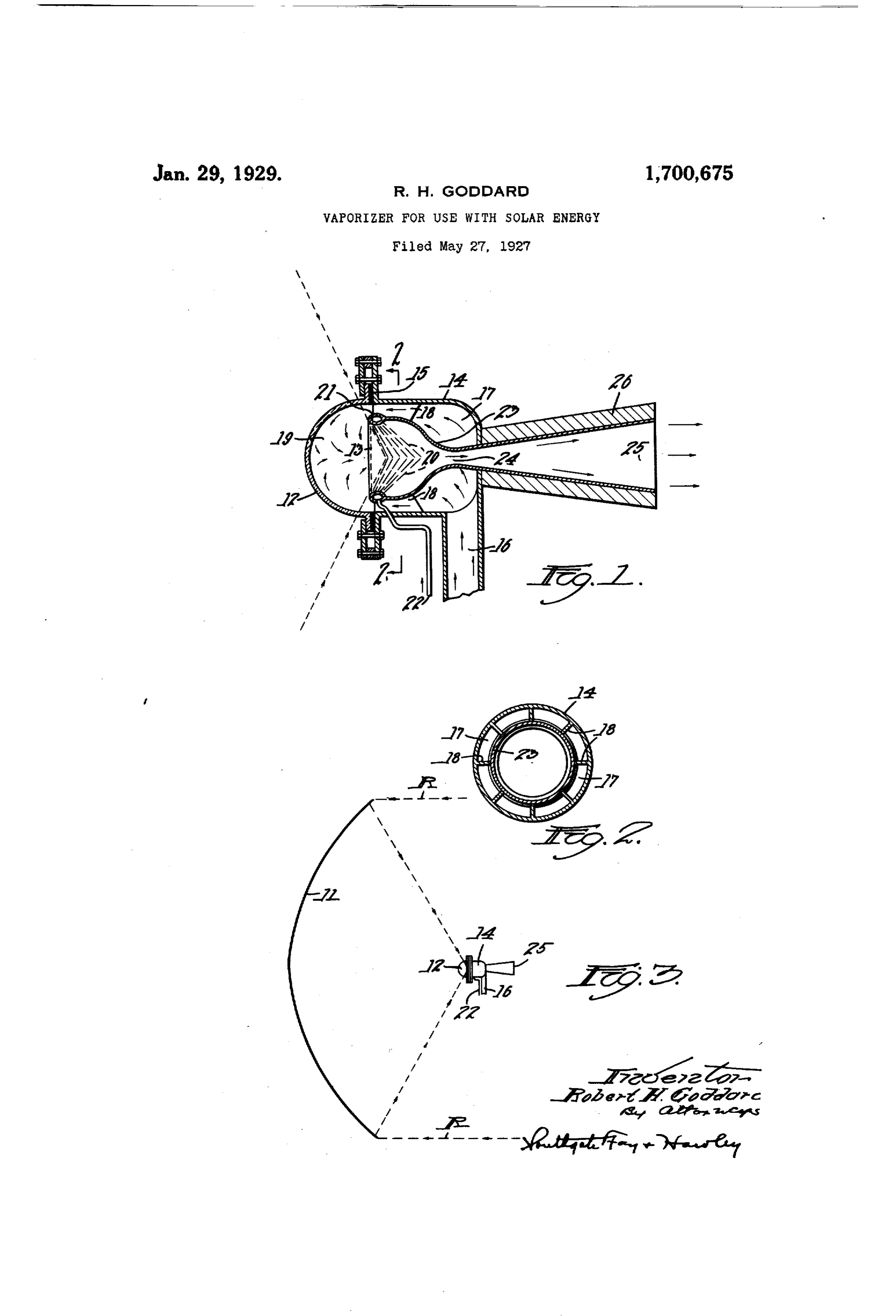
Fig. 1 is a vertical section through the va The increase in volume, produced by vapori porizer; zation results in a greatly increased speed of 20 Fig. 2 is a transverse vertical section, taken flow of the vapor through the constricted pas 5 along the line 2-2 in Fig. 1; and sage 24, from which the vapor emerges at a Fig. 3 is a diagrammatic view of the va high speed. The vapor commonly flows from porizer on a reduced scale and showing means the passage 24 directly into the expansion for concentrating the solar energy thereon. nozzle 25, from which it is drawn away to be 25 Referring to the drawing, the rays or ele sized, but the nozzle may be at times omit ments R of solar energy are reflected from a ted.
parabolic mirror. 11 (Fig. 3) and after pass The vapor, emerging from the nozzle at ing through a window 12 of glass or quartz, very high speed, may be used to operate a preferably of hemispherical form, said rays turbine (preferably a single stage turbine of 30 come to a focus in the area or locus 13 (Fig. small bulk, to avoid any considerable cutting 85 1). The window 12 is bolted to an outer cas off of the rays R of solar energy from the ing 14, with a packing-ring 15 inserted be mirror 11), or it may be used for any other tween. purpose where a high-velocity stream of gas The liquid to be vaporized, as water, enters or vapor is desirable. The vapor emerging 3. the vaporizer through a pipe 16, (Fig. 1) and from the passage 24 may be delivered direct O preferably passes through a water jacket 17, to a reciprocating engine, but this plan re and between guides or partitions 18 (Fig. 2), duces the heat efficiency.
which direct the liquid in stream-lines par The vapor, after being used in a turbine or allel to the axis of the vaporizer to the space 19 other device, may be led to a condenser, from 40 inside of and adjacent the window 12. which the two isis, as water and mercury, 95 As a liquid enters the region of the focus 13 may be separated by any well known means, of the mirror 11, it is preferably mixed with as by gravity or by centrifugal separators. a liquid having different optical properties, A very important advantage of the vapor such as mercury, which enters in the form of izer herin described results from the mixing 45 fine streams 20 from a hollow ring 21, this sec of the liquids substantially at the focus of OO ond liquid being introduced under pressure the mirror, as substantially all of the energy through a pipe 22. The main liquid to be va is taken up by the liquid stream itself, and porized, as water, porizer under should pressure also enter supplied va the heat-absorption is substantially instan by anytheavail taneous, and does not involve the loss of time 50 able means. which is demanded by other methods, such 105 Where the streams of liquid mix, at or near as flow of liquid through heated pipes. the focus 13, the mixture becomes opaque to This complete and instantaneous absorp radiation, owing to reflections and refractions tion of heat makes it possible to place the ex at the multitude of minute surfaces of contact pansion nozzle close to the focus, so that the 55 between the liquids of different optical prop distance through which the heated stream of O
Page 3
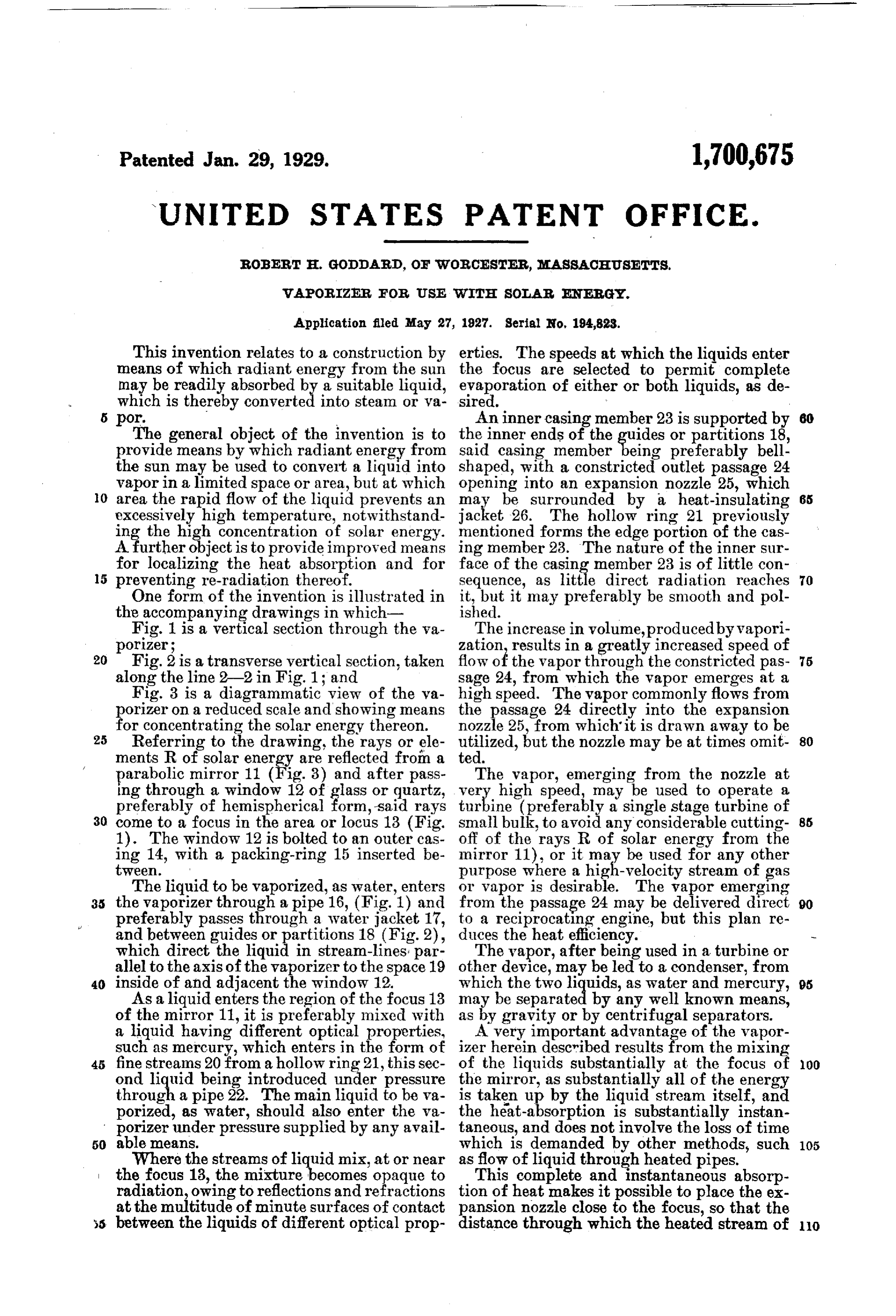
vapor passes can be made very small, and the 2. A vaporizer for use with solar energy heat loss, from the time the liquid is vaporized comprising means for focusing the rays of to the time when it is used, is reduced to a Solar energy, and means for absorbing the minimum. rays of solar energy in a heat-absorbing liq A further important advantage is that most uid substantially at the focal point, said liq 70 of the heat is absorbed at the focus, and only uid having a second liquid of different op relatively cool liquid is in contact with the tical properties mixed therewith. window. This not only serves to maintain 3. A vaporizer for use with solar energy all parts of the window cool, but it also pre comprising means to concentrate said energy O vents loss of heat from the focus by re-radia at a limited area, and means to supply an tion backward toward the mirror, for the real intimate mixture of liquids of different op son that the heat absorbed at the focus pro tical properties at said limited area. duces only relatively long heat waves, which 4. A vaporizer for use with Solar energy are wholly absorbed by the water that is ap having means for focusing the rays of Solar 8) 5 proaching the focus. energy, means to deliver a heat-absorbing An additional advantage lies in the hemi liquid to said vaporizer, and means to mix a spherical shape of the window 12, which per second liquid of different optical properties mits the employment of the least thickness for there with substantially at the focal point. a given pressure, and which cannot become 5. A vaporizer for use with solar energy intensely heated at any point, since it is much comprising a casing member, means to con langer than the focus. centrate said energy at a locus substantially Another advantage lies in the continuous within said casing member, means to cause a stream-line flow from the point where the heat-absorbing liquid to flow through said vapor begins to be heated to the point where locus, and means to introduce a second liq 25 it is used in the turbine, or other apparatus. uid thereto substantially at said locus of O The water jacket around the casing member energy concentration.
23 prevents loss of heat by conduction. 6. The combination in a vaporizer as set The combination of the small area of heat forth in claim 5, in which said casing mem ed surface, the short travel of heated vapor, ber has a constricted outlet passage from 30. the lack of appreciable re-radiation, and the which the vaporized liquid flows at relative stream-line flow, reduces heat losses to a mini ly high speed.
mum, and makes possible a thermodynamic 7. The combination in a vaporizer as set efficiency which is unusually high for a heat forth in claim 5, in which said casing mem engine, besides permitting the apparatus to ber has a constricted outlet passage from be compact and of very light weight, particu which the vaporized liquid flows at relatively 00 larly for a solar vaporizer. high speed, and an expansion nozzle con It is evident that various modifications can nected with said outlet passage. be made without departing from the essential 8. The combination in a vaporizer as set nature of the invention. Thus the liquid to forth in claim 5, in which said casing mem be vaporized liquids, or of amay consist liquid withofa finely-divided a mixture of ber has a constricted outlet passage from 105 which the vaporized liquid flows at relative solid substance, such as carbon, in suspension. ly high speed, and in which said outlet pas Further, it may consist of a liquid of much sage is jacketed by one of said liquids. higher boiling point and lower freezing point 9. The combination in a vaporizer as set 45 than water, such as isobutyl alcohol or diethyl forth in claim 5, in which said casing mem 10 aniline, so that the thermodynamic efficiency ber has a constricted outlet passage from may be made high by heating the vapor to a which the vaporized liquid flows at relatively high temperature, and condensing at a low high speed, and an expansion nozzle connect temperature. ed with said outlet passage, and in which The shape and cross section of the parts said expansion nozzle is provided with a heat and the number and arrangement of mirrors insulating jacket.
may be widely varied, and the heat may be 10. The combination of a vaporizer as set focused in a line instead of a point. Many forth in claim 5, in which an annular tube is other changes may be made in my invention provided through which said second liquidis 55 by those skilled in the art, within the spirit introduced, said annular tube forming the 20 and scope thereof, as set forth in the claims, inner edge portion of said casing member and I do not wish to be otherwise limited to and having a number of relatively fine per the details herein disclosed, but what I claim forations through its inner wall.
S 11. A vaporizer for use with solar energy 1. A vaporizer for use with solar energy comprising an outer casing, an inner casing 25 having means for focusing the rays of solar member, guiding partitions connecting said energy, means to deliver a heat-absorbing casing and casing member, a transparent clo liquid to said vaporizer, and means to mix sure for the end of said outer casing, and a second liquid therewith substantially at means to direct concentrated solar energy 35 the focal point. through said transparent closure to a focal 30
Page 4
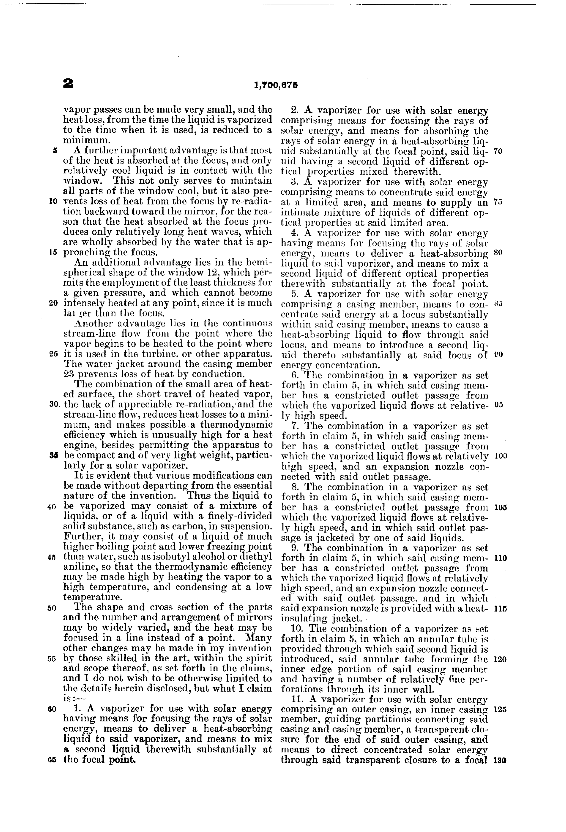
point substantially within said inner casing comprising an outer casing, an inner casing member. member, spacing supports between said cas 12. A vaporizer for use with solar energy ing and casing member, a transparent closure comprising an outer casing, an inner casing for the end of said outer casing, means to di member, a substantially hemispherical trans rect a flow of heat-absorbing liquid between 50 parent closure fixed to said outer casing, said casing and casing member, within said means to concentrate solar energy at a locus transparent closure, and within said casing within said transparent closure and substan member, and means to direct said solar energy tially within said inner casing member, and through said transparent closure and through O means to deliver a mixture of liquids of dif. said liquid to a focal point substantially with ferent optical properties at said locus. in said inner casing member. 13. A vaporizer for use with solar energy 17. A vaporizer for use with solar energy comprising an outer casing, an inner casing comprising an outer casing, an inner casing member, a substantially hemi-spherical trans member, guiding partitions connecting said 60 parent closure fixed to said outer casing, casing and casing member, a transparent means to concentrate solar energy at a locus to closure for the end of said outer casing, means within said transparent closure and substan direct a flow of heat-absorbing liquid be tially within said inner casing member, and tween said guiding partitions, within said means to deliver a mixture of liquids of dif transparent closure, and within said inner 20 ferent optical properties at said locus, the casing member, and means to direct said solar liquid which is in engagement with said trans energy through said transparent closure and parent closure being substantially unheated through said liquid to a focal point substan by said solar energy. tially within said inner casing member, and 14. A vaporizer for use with solar energy means to add a different liquid thereto with 70 comprising an outer casing, an inner cas in said inner casing member.
ing member, a substantially hemispherical 18. A vaporizer for use with solar energy transparent closure fixed to said outer cas comprising an outer casing, an inner casing ing, means to concentrate solar energy at a member, guiding partitions connecting said locus within said transparent closure and sub casing Af casing member, a transparent clo 5 30 stantially within said inner casing member, sure for the end of said outer casing, means and means to deliver a mixture of liquids of to direct a flow of heat-absorbing liquid be different optical properties at said locus, said tween said guiding partitions, within said liquids being under substantial pressure. transparent closure, and within said inner 15. A vaporizer for use with solar energy casing member, means to direct said solar 80 3 5 comprising an outer casing, an inner casing energy through said transparent closure and member, a substantially hemispherical trans through said liquid to a focal point substan parent closure fixed to said outer casing, tially within said inner casing member, and means to concentrate sclar energy at a locus means to add a different liquid thereto with within said transparent closure and substan in said inner casing member, one of said 40 tially within said inner casing member, and liquids jacketing said inner casing member means to deliver a mixture of liquids of dif to prevent loss of heat therefrom. ferent optical properties at said locus, said In testimony whereof I have hereunto inner casing member having a restricted out affixed my signature.
let passage for the vaporized liquid.
45 16. A vaporizer for use with solar energy ROBERT H. GODDARD.
Provenance
- Collection
- Cited prior art
- Original PDF
- patentimages.storage.googleapis.com →
- Filed
- 1927-05-27
- Pages
- 4
- Method
- pdftotext (the PDF's own text layer) + pdftoppm 300dpi page scans
- Source
- Google Patents bibliographic record
- Granted
- 1929-01-29
- Inventors
- Robert H Goddard
- Transcribed from
- patentimages.storage.googleapis.com →