patent · US4696338
Latent heat storage and transfer system and method
29 September 1987
Page 1 — bibliographic record
United States Patent 19 11 Patent Number: 4,696,338 Jensen et al. 45) Date of Patent: Sep. 29, 1987 (54) LATENT HEAT STORAGE AND TRANSFER 4,466,478 8/1984 Carlsson et al. ............... 165/104.17
SYSTEM AND METHOD
FOREIGN PATENT DOCUMENTS
(75) Inventors: Eric A. Jensen, Salt Lake City, Utah; 28436. 3/1979 Japan .............................. 165/104.17 James Hitchin, Del Mar, Calif;
Albert G. Tsai, San Diego, Calif.; Primary Examiner-Albert W. Davis, Jr.
Gustaf O. Arrhenius, La Jolla, Calif. Attorney, Agent, or Firm-Brown, Martin, Haller & Meador (73) Assignee: Thermal Energy Stroage, Inc., San
Diego, Calif. 57) ABSTRACT 21) Appl. No.: 708,669 Heat storage and transfer system and method in which a liquid-solid phase change material and a liquid-vapor 22) Filed: Mar. 6, 1985 phase change material selected for coaction with each other are disposed in a container with a body of the
Related U.S. Application Data liquid phase of the liquid-vapor material in continuous 63 Continuation of Ser. No. 382,971, Jun. 1, 1982, aban contact with a body of the liquid phase of the liquid doned. solid material for superior heat transfer between the materials for giving up and transferring sensible heat 51) Int. Cl.' .............................................. F28D 21/00 and liquid to solid phase change latent heat to vaporize (52) U.S. Cl. .............. w o os s a o a 165/1; 165/10; liquid-vapor phase change material and vapor to liquid 165/104.11; 165/104.17; 252/70; 252/69 phase change latent heat to a condenser/heat exchanger 58 Field of Search ...................... 165/104.17, 104.11, and also for superior heat transfer from a heat source 165/10, 1; 252/70, 69 such as a solar or electric heater by giving up the heat 56) References Cited of condensation of a vapor phase to a solid-liquid mate
of melting.
2,095,008 10/1937 Phillip ............................ 165/104.21 4,154,292 5/1979 Herrick .......................... 165/104.11 28 Claims, 3 Drawing Figures
SS3 VWMVVV
Page 2
Drawing sheet — no readable text.
Page 3
Drawing sheet — no readable text.
Page 4
droplets and crystals of the PCM which clog the sec
LATENT HEAT STORAGE AND TRANSFER ondary heat exchange system. The method is also ineffi SYSTEMAND METHOD cient because of the unsatisfactory heat carrying capac ity of the oil or other non-volatile heat transfer fluids.
This is a continuation of application Ser. No. 382,971 5 A further heat exchange system has involved pump filed June 1, 1982, now abandoned. ing a molten salt mixture at a temperature of from 250 BACKGROUND OF THE INVENTION degrees to 350 degrees C. into a boiler, injecting water into the molten salt mixture where it is flashed into
Heat storage is required in solar systems to buffer the steam by the molten salt and the steam is passed to a fluctuations in and between energy collection and re 10 condenser/heat exchanger to deliver heat. The slurry of lease. Heat storage also enables use of waste or surplus molten salt and salt crystals formed in delivering latent heat from industrial processes. Heat storage at low tem heat is pumped out for heating to melt the crystals in the perature is also required to allow the use of cooling slurry before return to the boiler. The system requires machinery during times other than the time of use of the complicated and expensive apparatus and suffers from cooling capacity for space cooling, air conditioning and 15 the further disadvantages that the steam tends to carry other purposes. salt over to the condenser/heat exchanger surface, that While heat may be stored by raising the temperature the area of heat transfer from the salt to liquid water is of the storage material, as in sensible heat storage, latent limited to the water jets before conversion of the liquid heat storage offers numerous advantages over sensible water to steam, that the temperature range is unneces heat storage. The heat of transition in melting is gener 20 sarily high causing safety and implementation problems ally greater than the heat capacity of a material inte in high entropy heat applications, and that the system grated over a practical temperature range, hence a requires substantial mechanical energy. A further disad larger amount of energy can be stored in a given storage vantage is that in order to remain fluid enough for volume as latent heat of melting than as sensible heat. pumping and to allow passage of water and steam for Additionally, latent heat storage systems provide heat 25 delivery of heat, only a limited proportion of the salt in at a constant output temperature, the transition temper the boiler can be allowed to crystallize, thus limiting the ature of the phase change, in contrast to a sensible heat effective energy density of the system. Finally, the storage system in which the output temperature de method is not applicable to supercooling salt hydrate creases as heat is removed. melt storage systems, but only to anhydrous salt melts at In a latent heat storage system, heat is added to the 30 high temperature which inevitably lose their heat to the storage medium until it has undergone complete phase environment; only short term storage, associated with change. The transition most commonly used is solid to substantial heat losses, could thus be achieved if use of liquid. Systems based on the melting of salts or salt this method were attempted.
hydrates are convenient to work with and have high BRIEF SUMMARY OF THE INVENTION energy densities. Input heat is stored as heat of melting 35 and additionally as sensible heat and, when heat is re The present heat storage and transfer system and quired, the melt, which may indefinitely be kept super method provide high energy density and high heat cooled in the intermin, is nucleated and heat is removed delivery efficiency through the combination of a liquid as the liquid crystallizes. solid phase change material and a liquid-vapor phase A major problem in previously known systems of this 40 change material with partial solubility in the liquid-solid type is the removal of heat from the crystallizing body. phase change material and selected for coaction with The use of conventional heat exchangers immersed in each other and disposed in a container with a body of the solid-liquid phase change materials (hereinafter re the liquid phase of the liquid-vapor material in continu ferred to as PCM) has been hampered in known systems ous contact with a body of the liquid phase of the liquid by two significant problems. During the heat removal 45 solid material for superior heat transfer between the cycle, the solid crystallizes and coats the exchanger materials for giving up and transferring liquid to solid surfaces thus increasing their thermal resistance and phase change latent heat to vaporize liquid-vapor phase decreasing the rate of heat transfer. Also, in the solid change material and, in one form of the invention, state, the materials may contract away from the heat vapor to liquid phase change latent heat to a conden exchanger surfaces which leads to a decrease in the 50 ser/heat exchanger.
initial rate of melting during the heating cycle. Efforts A notable feature of the subject invention Latent to solve these problems have included coating the heat Heat Storage and Transfer System that yields thermal exchange surfaces with surfactants and non-adhesive energy efficiency advantages over earlier systems is the materials, such as "Teflon' without notable success. use of liquid-solid and liquid-vapor phase change mate Attempts to modify the crystal habit of the PCM with 55 rials that permit the formation of refrigerant gas hy additives to weaken the crystal aggregate have not drates, or clathrates. Clathrate formation is realized by provided a satisfactory remedy. And mechanical meth the selective use of liquid-vapor phase change materials ods for clearing the heat exchange surfaces are cumber that exhibit up to 5% solubility in the liquid-solid phase some, energy demanding and have had only limited change material.
effectiveness.
Heat exchange by direct contact between the crystal BRIEF DESCRIPTION OF THE DRAWINGS lizing PCM melt and an immiscible, non-volatile heat The invention will be discussed with reference to the transfer liquid has been proposed to eliminate the need associated drawings in which:
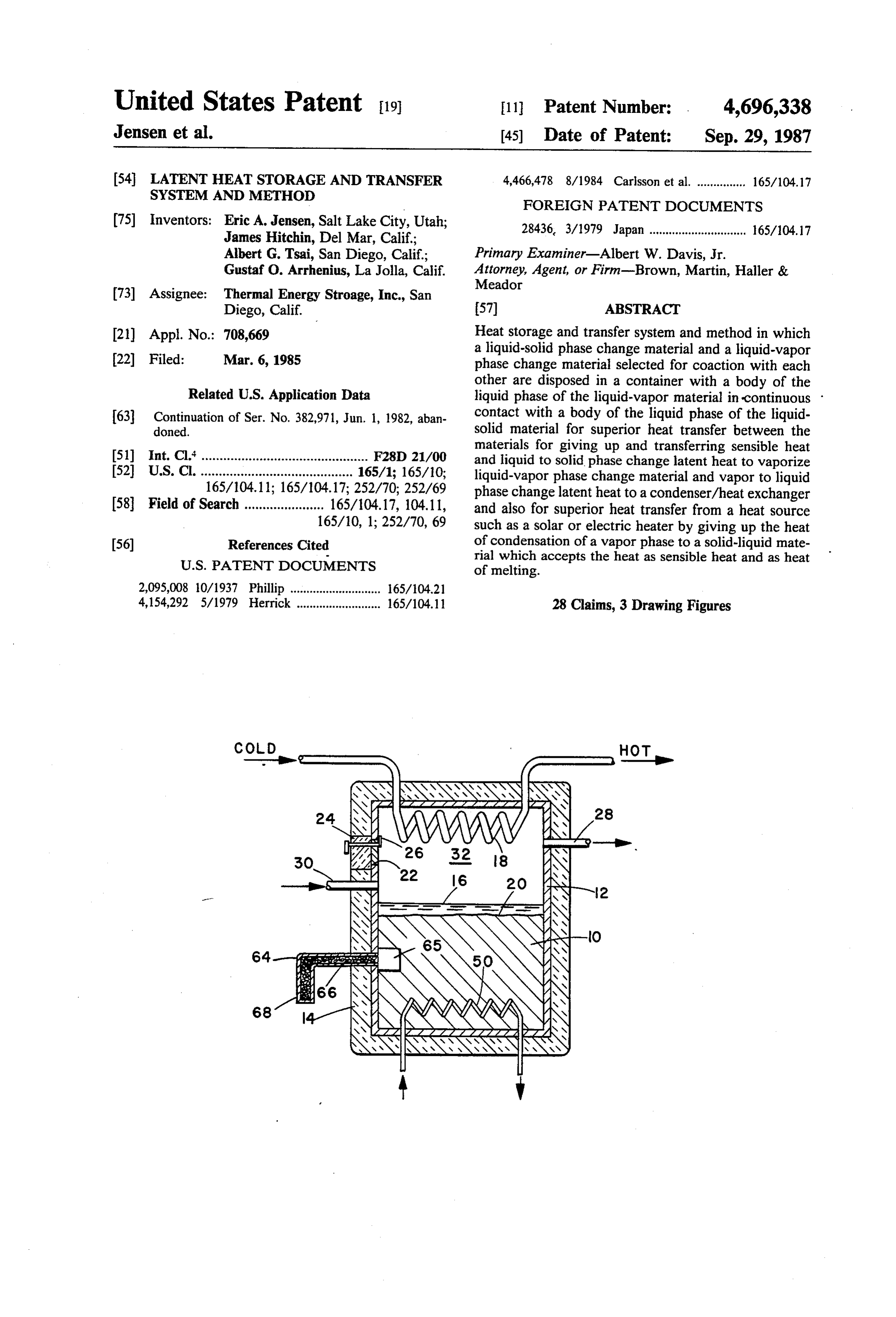
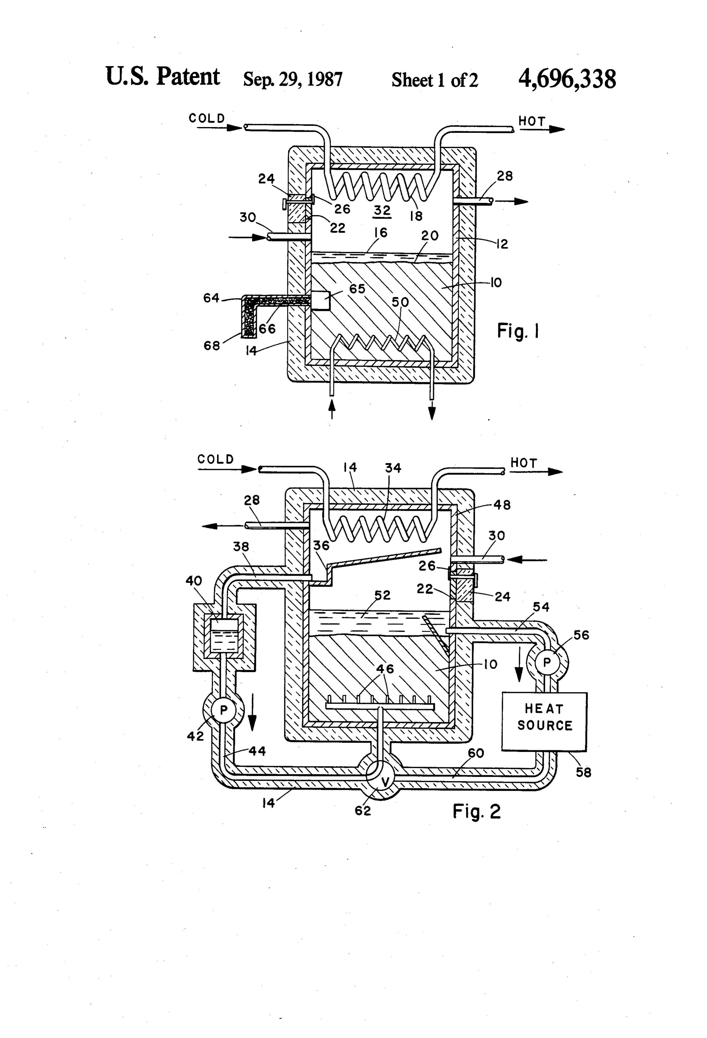
for a conventional heat exchanger. Silicone oil and FIG. 1 is a side elevation view in section of one form other immiscible, non-volatile fluids are pumped 65 of the latent heat storage and transfer system of the through or swirled over the molten PCM and heat is present invention; and removed as sensible heat of the fluid. This method suf FIG. 2 is a side elevation view in section of a further fers from the difficulty that the fluid stream may carry form of the latent heat storage and transfer system.
Page 5
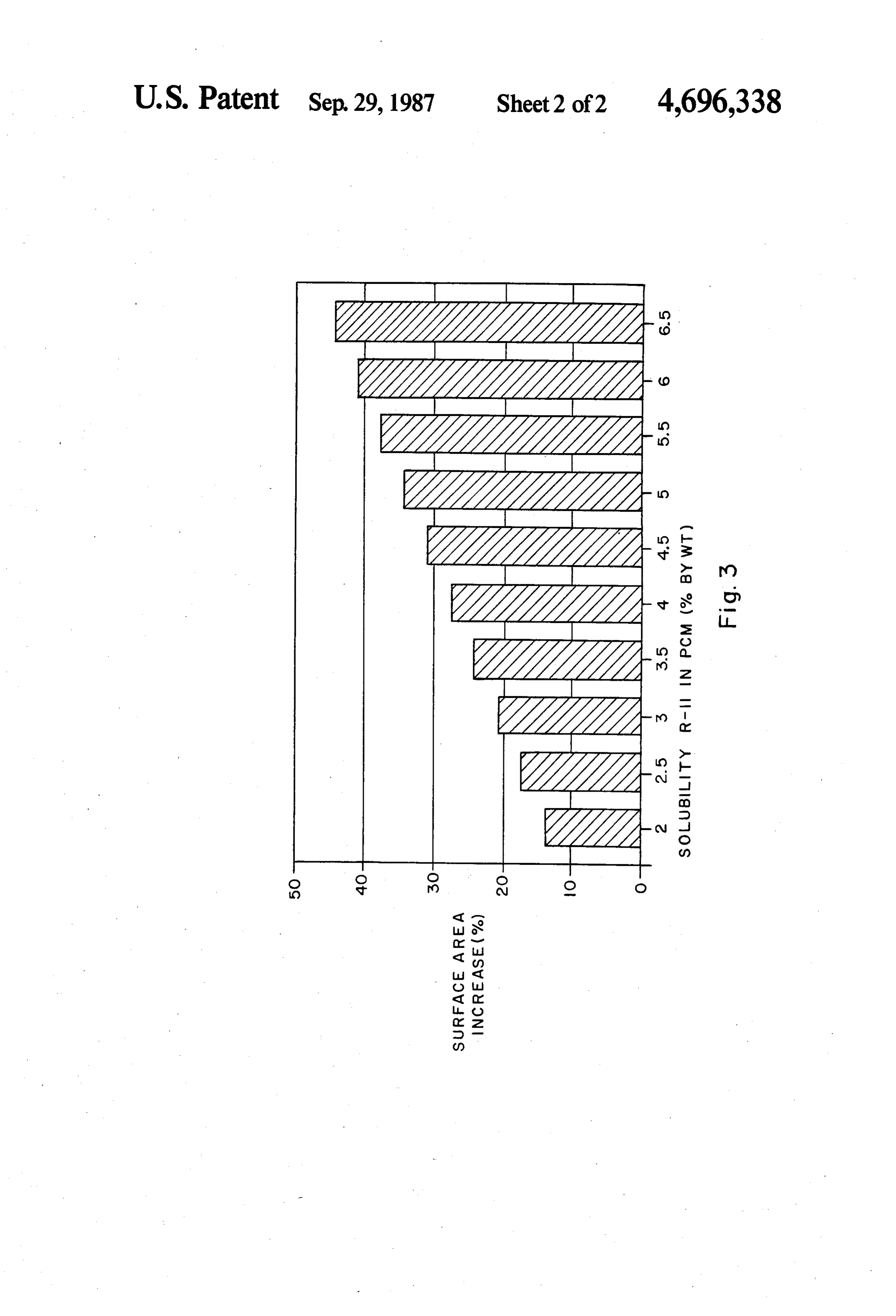
FIG. 3 shows the relationship between the effect of -continued increasing solubility of the heat transfer material, R-11, LATENT and the surface area available for heat transfer. MELTING HEAT OF
TEMPERA- MELTING
DESCRIPTION OF THE PREFERRED 5 PHASE CHANGE MATERIAL TURE (C.) (kJ/kg) EMBODIMENTS Magnesium nitrate hexahydrate 90 60 In the method and system of the present invention, Mg(NO3)2.6H2O heat is extracted from a molten body of crystallizable Eutectic of magnesium chloride 59 141 hexahydrate and magnesium phase change material, PCM, by disposing the molten nitrate hexahydrate body 10 of PCM in a closed container 12 surrounded by 10 MgCl2.6H2O and Mg(NO3)2.6H2O insulation 14 and providing a body of heat transfer and Eutectic of ammonium chloride sodium sulfate decahydrate
material in liquid state shown as a layer 16 on the sur NH4CI.Na2SO4.10H2O face of the body of PCM. As discussed below, the body Water ice O 334 of heat transfer liquid may also be below the body 10 of H2O
PCM where its specific gravity is greater than that of 15 the PCM. Heat transfer materials are chemically stable Heat transfer fluids are selected to have boiling points volatile liquids immiscible with or partially soluble in near but fot higher than, and preferably at least about the molten PCM, for forming a stoichiometric compo 10 degrees C. lower than, the melting point of the PCM nent of the crystalline phase change material and having boiling points at operational pressures selected relative 20 at the dynamic vapor pressure maintained in the con tainer and are used in sufficient quantities that portions to the melting points of the phase change materials for of the fluid may remain liquid in contact with the PCM controlled vaporization of the liquid by heat from crys where boiling of the liquid will provide a mixing action tallization of the phase change material while maintain to insure continuous effective contact between the liq ing portions of the heat transfer material in liquid state uid and the latent heat releasing crystallizing melt. In in contact with the PCM. By vaporizing the transfer 25 general material and thereafter condensing it on a conventional tile organic ortransfer useful fluids are chemically stable, vola inorgaic. liquids, non-reactive with and condenser/heat exchanger 18, the system takes advan partially soluble in the molten tage of the heat of vaporization of the liquid which is cally included in the crystallizedPCM PCM. and stoichiometri
The liquids may much greater than its specific heat and therefore pro 30 thus be immiscible with the molten PCM, but prefera vides much greater heat transfer efficiency. Addition ally, maintaining the body such as the layer 16 of liquid bly, in cases discussed below, are partially soluble in the molten material. Halocarbons, mainly substituted meth transfer material in contact with the PCM results in anes and ethanes, have been found desirable, but simple boiling of the transfer liquid in contact with the body of hydrocarbons
PCM and provides mixing of the liquid and PCM at the and other chemically stable fluids are interface 20 to insure continuous effective contact be 35 useable provided that they are capable of forming clath rates and have the appropriate vapor pressures, (boiling tween the transfer liquid and the latent heat releasing points), crystallizing melt and eliminates the need for mechani ing and aswater specified above. For instance, for space heat heating, preferred boiling points would cal stirring devices. be in the range of from about 30 degrees C. to about 80 Phase change materials, PCM, for use in the present degrees C. at atmospheric system are selected from crystallizable substances of 40 this range may be useful forpressure but liquids outside delivery or absorption of which the melting point is in a range determined by the heatin special situations. With these liquids, the internal temperature at which it is desired to deliver heat and, in pressure of the system is increased, for example, some situations, by the temperature of a heat supply about one atmosphere overpressure to elevate theupboil to available for recharging heat to the body of PCM. It is 45 ing temperatures to values suitable for domestic water also important to select materials which have a large heat of crystallization. For domestic space and water and space heating and cooling at the output of the sys ten.
heating and cooling, materials which change phase A partial list of heat transfer fluids for use in the from liquid to solid attemperatures in the range of from present system includes:
about -20 degrees C. to about 95 degrees C., are useful.
Suitable phase change materials include: 50
Halocarbons ("Freons") Boiling point (1 atm.) C.
LATENT (CCl2F)2 R-113 47.6
MELTING HEAT OF CCF R-11 23.8
PHASE CHANGE MATERIAL
TEMPERA.
TURE (C)
MELTING
55 (CCIF2)2 R-14 3.8
Sodium thiosulfate 48 200 (CBrF2)2 FC-14B2 47.3 pentahydrate CH2Cl2 R-30 40.0
CH3COONa.3H2O 60 and other stable organic liquids such as hexafluoroiso Aluminum ammonium sulfate dodecahydrate 93 164 propanol, B.P. 58.2, 1,1-difluoroethane, B.P. -25.0", 1,1,1-chlorodifluoroethane, B.P. -9.7, hexafluoroace
Calcium chloride hexahydrate 32 170 tone, BP. -28, and 2-methylbutane, B.P. 28, and am monia, NH3 B.P. -33.4 C., which is particularly useful
Disodium hydrogen phosphate 36 266 65 in low temperature applications because of its high heat dodecahydrate of vaporization.
Sodium sulfate decahydrate 32 246 It is noteworthy that when the PCM is composed of Na2SO4.10H2O H2O and a heat transfer fluid such as R-11, R-21 or R-12
Page 6
shown above, or other similar refrigerants, that the interface 20 between the two liquids. But, as boiling subject invention Latent Heat Storage and Transfer continues, turbulence causes mixing of the two compo System exhibits thermal energy efficiency advantages nents and boiling occurs from the mixture within the over earlier systems due to the formation of refrigerant body of crystallizing melt as well as at the interface 20. gas hydrates, or clathrates. A Clathrate is a compound This self-mixing is also partially responsible for creating formed by the inclusion of molecules of one kind in a mass of small crystals which do not form a solid mass cavities of the crystal lattice of another. The latter one or crust, but, instead, a suspension of isolated crystallites is for the non-stoichiometric combining H2O and the in the fluid. This action enhances a steady release of various refrigerants. Gas hydrates form a class of clath heat from the melt and eliminates the thermal inhomo rates or inclusion compounds in which a hydrogen O geneity characteristic of non-convective crystallizing bonded water molecule lattice encloses a guest mole PCM systems.
cule of gas. Gas hydrates have a high heat of formation As noted above it is, in cases where the heat transfer which make them ideal as cool storage media. The size fluid is less dense than the molten PCM, preferred to use of the guest molecule encased in the hydrogen bonded heat transfer fluids which are partially soluble in the water molecule lattice is one factor determinative of 15 molten PCM, since these fluids give further improve clathrate formation. A second factor is the solubility of ment in internal boiling and fluidization of the body of the gas molecule in the H2O component of the phase PCM due to vaporization of the dissolved fluid within change material. It is necessary that there be significant the body of the melt. This improvement becomes par solubility of the guest molecule and generally, up to 5% ticularly effective where the solubility of the heat trans solubility is desired. There are many gases which can 20 fer fluid exceeds about 2% by volume, preferably ex form gas hydrates, including the noble gases, halogens, ceeding about 5% by volume based on the volume of straight-chain hydrocarbons and, halogenated hydro the Imolten PCM.
carbons or common refrigerants used in vapor compres It has also been found desirable to add a small amount sion cycles. of water or other protic solvent to the PCM in excess of It is important to note that partial solubility of the 25 its water of crystallization. The additional water or heat transfer fluid is required for several reasons. In other solvent is enough to form a residual PCM solution those instances where the PCM is composed of a salt, which, if distributed evenly throughout the mass forms partial solubility permits heat transfer via nucleate boil a liquid film separating the crystals. In practice, about ing. Nucleate boiling is a well known phenomena and 5% of water has been found effective to improve the improves the overall heat transfer rate in a binary sys 30 freedom of crystals in a totally spent PCM mass to tem, as is present in the invention, by increasing the heat move when the mass of PCM is stirred. transfer surface area between the heat transfer fluid and Vapors of the heat transfer fluid pass to the heat the PCM. If the heat transfer fluid is insoluble, then exchanger/condenser 18 where they are condensed to boiling occurs only at the limited interfacial area be give up their heat of condensation to the water or other tween the layers of the heat transfer fluid and the PCM. 35 fluid, including air, passing through the coils of the In those instances where clathrate formation is in condenser 18. In the form shown in FIG. 1, condensed volved in the heat storage/exchange events, partial heat transfer liquid is permitted to fall back in the layer solubility of the heat transfer fluid is key for two rea 16 of liquid on the body 10 of PCM to replenish the sons. First, partial solubility forms nucleate boiling, and body of liquid.
second, partial solubility is necessary to effect clathrate An important advantage of the system using molten formation. PCM and heat transfer fluid is that, since the PCM For the operation of the system to supply heat, the supplies heat at a constant temperature, simple cutting body 10 of PCM which may be in molten condition or off the fluid passing through the coils of the condenser may be melted later is introduced into the container 12 will stop evolution of heat from the PCM except for the through the port and the closure 24 is secured in place 45 amount balancing the, ideally negligible, heat loss by latch 26. Air and other gases in the container 10 are through the insulation 14. That is, aside from losses due then evacuated through the pipe 28 and heat transfer to imperfect insulation of the system, the vapor pressure fluid is introduced through the pipe 30 to form a second of the heat transfer fluid will build up to a value at body, shown as layer 16 in contact with the PCM. The which no further vaporization of the fluid can occur at heat transfer fluid can also form as a layer below the 50 the fixed temperature at which the phase change of the PCM, (not shown) if its density is higher than that of the PCM can supply heat. Conversely, in the moment that PCM; the heat transfer fluid may also, if its density is heat withdrawal through the condenser is resumed, closely matched to that of the PCM, become dispersed vaporization of the liquid, and transfer of useable heat through the PCM. Mechanical details of the system are out of the PCM begins again.
then modified accordingly. The quantity of PCM intro 55 In another form, (see FIG. 2), condensate from the duced is such that after melting, there will, in vapor heat exchanger/condenser 34 may be collected in a transfer applications, be a free space 32 for passage of trough 36 and flowed through a conduit 38 to a fluid vaporized heat transfer fluid to the heat exchanger/con reservoir 40 which may or may not be insulated. Fluid denser 18. The quantity of heat transfer fluid used is collected in the reservoir is then forced by the pump 42 sufficient to saturate the molten PCM and to maintain a through a conduit 44 to injection nozzles 46 disposed in body of liquid continuously in contact with the PCM the lower portion of the container 48. The injected fluid during operation. provides further turbulent mixing in passing up through The densities of the heat transfer fluids are, in the the molten PCM to ensure good contact between the configuration shown, lower than the densities of the fluid and the molten PCM and a high rate of vaporiza PCM so that the heat transfer liquid remains as a layer 65 tion. This form of the system is particularly useful to 16 on top of the body of molten PCM in the container. ensure that the PCM forms a crystallite slurry or mush Heat transfer from the PCM causes boiling in the region where the heat transfer fluid is lighter than and insolu of largest temperature differential which, initially, is the ble in the molten PCM.
Page 7
The PCM may be recharged by a simple heating ent temperature in a supercooled state in which it may element 50 disposed in the body of material as shown in remain practically indefinitely until it is purposefully FIG. 1. This heating element 50 may be an electrical nucleated by opening of valve 65 leading to release of resistance element using, for example, offpeak electrical the stored latent heat of crystallization at the melting energy or a heat exchange element through which a temperature of the PCM. It will be understood that the steam line or a waste heat conduit or a solar heated fluid heat transfer liquid circulation, PCM heating and melt may be passed. ing and other apparatus and method parts of the systems Also, as shown in FIG. 2, because the exhausted shown in FIGS. 1 and 2 may be used in any combination PCM in this system is a crystallite slurry or mush in to make complete charge discharge cycles. stead of a solid mass, the PCM may be recharged by O While the operation of the system has been described direct circulation of heated transfer fluid upwards primarily for the storage and delivery of heat, it will be through the crystalline slurry or mush to melt it. In this understood that the system may also be used for storing form, transfer fluid either from the layer 52 in the con thermal energy in a cooling system, and the term "heat tainer 48 or from storage drawn off through the pipe 54 transfer' is used to make this fact clear. In a cooling is forced by pump 56 through an external heat source 58 15 system, the heat transfer liquid is run through a heat which may be waste, heat, steam, a solar collector, an exchanger accessed to a cold sink, for example, cold air or water cooling unit or other source and then night air, and takes up heat from the PCM to solidify it. through a pipe 60 for injection through the nozzles 46 When cooling is needed, the heat transfer liquid is into the body of PCM. These nozzles 46 may be the pumped to the point where heat is to be absorbed, e.g. same nozzles as used to supply heat transfer fluid to the 20 a room or other space to be cooled and vaporizes to PCM in the heat supply mode, by using the valve 62 to effect cooling. The vapor is then returned to the body cut off connection between the pump 42 used during of solidified PCM where it melts and gives up heat to heat supply and allow passage of fluid from the recharg the PCM and is condensed for recirculation. ing pump 56. Heat transfer fluid condensed in melting The following examples are provided to aid in under the body of PCM may be withdrawn and pumped for 25 standing the invention but it is to be understood that the heating to the external heat source and again injected invention is not restricted to the particular apparatus, into the mass of PCM. materials, temperatures, or procedural details of the In an alternative system useful particularly where the examples.
heat transfer fluid is partially soluble in the PCM to EXAMPLE 1 induce turbulence through internal boiling and/or 30 where the heat transfer fluid has a higher specific grav Solid to liquid phase change material (PCM) in the ity then the PCM, the heat exchanger element may be in form of sodium acetate trihydrate granules containing contact with or immersed in the molten PCM. The 4.8 mass percent of added water is loaded into the con turbulence and the retrograde boiling of the heat trans tainer of a heat storage and supply system similar to that fer fluid expelled from the crystallizing PCM serves to 35 shown in FIG. 1 but with no. 50 indicating a resistance resist build-up of crystallized PCM on the heat ex heater powered by electricity, obtainable at a low off changer surface during the heat removal cycle and heat peak rate. The container is sealed, evacuated to remove transfer by condensation of heat transfer fluid on the air and other gases and loaded with a volume of CCl3F heat exchanger is augmented by heat transfer by con (Freon 11) corresponding to about 5 percent of the duction from the hot heat transfer fluid in liquid phase volume of the PCM. The heat transfer liquid (Freon 11 and from the molten PCM to the heat exchanger sur with density 1.49 at 21 C. is lighter than the crystalline face. Additionally, the turbulence provides a high mass PCM with density 1.52.
flux of the molten PCM and the heat transfer liquid past The PCM is charged by melting with the electric the heat exchanger surface to increase the rate of heat heater and stores 265 kJ/kg (344 kJ per liter of melt) as removal. The presence of the heat transfer fluid is also 45 latent heat of melting. An additional 3.22 kJ/kg is stored useful during the heating of the PCM since the fluid will as sensible heat for each degree C. that the PCM is transfer heat from the heat exchanger surface to the heated above the melting temperature at 58' C. At melt PCM across any spaces which may have developed ing the density of the PCM decreases to about 1.3, less between the surface and the solidified PCM. than the density of 1.40 of the heat transfer fluid at 58 Where the PCM has been completely melted and it is 50 C. This results in an inversion of the liquids so that the desired to prevent it from supercooling, a small diame originally lighter Freon heat transfer fluid now sinks ter side tube 64 (see FIG. 1) including a horizontal and forms a layer below the PCM melt; this inversion portion 66 communicating with the body of PCM contributes to mixing of the system at melting. below its surface 20 and a vertical portion 68 extending As heat is added to the system, an increasing portion outside the container 12 is filled with solid PCM. Since 55 of the Freon will enter the free space above the melting the tube 64 is not insulated, the PCM inside it will re PCM as vapor and increase the internal vapor pressure main solid. When the body 10 of molten PCM in the in equilibrium with the liquid Freon. When the solid-liq container 12 cools to its freezing point, the solid PCM in uid phase change material is completely melted, the the tube 64 will trigger crystallization of the PCM in the device is fully charged by latent heat. Heating may be container 12 without physical transfer of any seed crys 60 continued by adding sensible heat to the PCM until it tals from the tube to the PCM. The tube 64 may be reaches a predetermined upper temperature limit where provided with a valve 65, kept at the same temperature a switch is operated to disconnect the heat source. The as the PCM. By closure of valve 65, the charged PCM system remains in this state (except for heat loss by is isolated from the nucleation tube 64 to prevent nucle imperfect insulation) until the discharge mode is initi ation and release of the heat of crystallization from the 65 ated.
PCM. When the sensible heat is withdrawn from the To remove heat from the system (in the heat use PCM either through the condenser or by slow heat mode), cold water is allowed to flow through the heat leakage through the insulation, the PCM cools to ambi exchanger coil at the top of the container and the hot
Page 8
Freon vapor condenses on the exchanger surface, trans The system delivers heat efficiently and is easily ferring 33 kJ/kg as heat of condensation and an addi stopped and started as in the system of Example 1. The tional amount of sensible heat to the water flowing crystallized material after discharge of the system is a through the coil. Liquid Freon drips off the condenser crystal mush or slurry.
back to the body of molten PCM through which it sinks down, absorbing more heat until it revaporizes by boil EXAMPLE 3 ling. In this example, the heat storage material is a near By this removal of sensible heat, the temperature of eutectic mixture of MgCl2.6H2O-Mg(NO3)2.6H2O the molten PCM is brought down to the melting point, with 4 percent excess water, and the volatile heat trans 58 C., where crystallization of the PCM begins, initi O fer material is Freon 21, CHCl2F. In this example, the ated by the crystals in the nucleation tube 64. The crys apparatus shown in FIG. 2 is used in which the volatile tallizing phase change material now begins to release its low density heat transfer liquid on the surface of the latent heat of fusion at a rate of 265 kJ/kg of crystalline molten material is withdrawn, heated by an external sodium acetate trihydrate and continues this energy heat source and pumped release at a constant temperature of 58' C. until practi 15 nozzles (46) into the bodyback for injection through the cally all of the PCM has crystallized. During this entire provide improved agitation of this phasePCM of crystalline mush to process, and until ambient temperature has been rial for superior heat transfer between the PCM andmate change the reached, the Freon below and within the PCM boils Freon during melting. In this example, the injected vigorously, creating turbulent mixing and efficient heat Freon rises up through the mush of salt solution and exchange with the PCM by greatly increasing the 20 crystalline eutectic material to melt it at a temperature contact surface area between the two liquid phases and near 56' C. When the system is completely melted, the the crystals. The exchange is augmented by the settling of the condensed Freon through the PCM. This self heating circuit is cut off by the valve, the discharge mixing promotes rapid and efficient heat removal from circuit is opened by turning the valve and cold water is the melt. 25 supplied to the condenser coil. The Freon 21 has a A continuous cycle is produced with the Freon being boiling point of 56' C. at about 3 atm. and a heat of circulated as vapor and liquid between the condenser vaporization/condensation of 44.89 kJ/kg. and the body of boiling liquid Freon below and within In this case, the Freon condensing on the coil is col the crystallizing melt. The cold water entering the con lected by the trough and led to a Freon reservoir from denser coil absorbs the vapor transported heat released 30 which it is pumped and injected into the body of molten from the melt and leaves as hot water. The cycle contin material through the jets in the lower portion of the ues until the crystallization of the melt at 58 C. has container. The turbulence and dispersion of Freon by reached completion and until thereafter excess sensible these jets takes the place of the self-mixing effect of heat has been removed and ambient temperature has more vigorous internal boiling and boiling from below been reached. The crystallized mass is mushy in consis 35 which occurs with other pairs, although internal boiling tency with Freon distributed through it and as a layer at occurs with this pair but to a smaller extent than with the surface due to the larger density of the crystallized the previous examples.
PCM.
EXAMPLE 4
The discharge of heat from the system can be inter rupted at any point during the discharge mode by shut 40 In a system operated for refrigeration, the heat stor ting of the flow of cold water through the condenser. age material (PCM) is water ice, with heat of melting This stops condensation of vapor on the coil which 335 kJ/kg with which 5.5% by weight of diethylene increases the vapor pressure within the container so that glycol has been included so that the frozen PCM is a boiling of the Freon ceases. Cooling and crystallization slush of ice crystals instead of a solid mass. The volatile of the melt then stop immediately since the Freon can 45 heat transfer fluid is 1,1,1-chloro difluoroethane (Freon no longer vaporize and cool the melt. Allowing for R-142b), having a boiling point of -9.7 C. at 1 atm, insulation losses, the device will remain in the partially and a density larger than that of water and ice so that it discharged state until cold water is once again passed forms a layer below the ice slush (PCM). When the through the condenser. system is charged for cooling (PCM frozen), the heat 50 transfer fluid in liquid state is pumped from the bottom
EXAMPLE 2 of the container through a coil in the space to be refrig The procedure of this example is similar to that of erated and is vaporized to withdraw heat from and cool Example 1 except that heat for melting the liquid-solid the space. The vapor then is returned into and is con phase change material is supplied by a flow of solar densed on the ice slush PCM to release its heat of vapor heated (CCIF2)2 (Freon 113) through a heat exchanger 55 ization which is taken up in melting portions of the ice coil (50) disposed in the lower portion of the container crystals of the slush. The condensed heat transfer fluid and that a different solid-liquid phase change material sinks to the bottom and is thus separated from the -melt and different internal liquid-vapor heat transfer fluid are water mixture, and is pumped through the system for used. continued refrigeration of the space until the ice crystals In this example, granules of sodium thiosulfate penta have completely melted.
hydrate containing 5% water, and Freon 114, (CClF2)2, The system may be recharged at night when electric are used as the active internal components. The gran power is available at low price, or during winter when ules are melted and store heat at a rate of 180 kJ/kg of outside temperature falls below 0°C., by a refrigeration latent heat at the melting temperature of 48 C. Above coil (18) disposed in the upper part of the container. The the melting temperature heat is stored as sensible heat at 65 liquid pumped through this coil is cooled by an electri 2.38 kJ/kg'C. The Freon 114 has a boiling point at 3 cally powered refrigerator or by exchange with outside atm. pressure of about 48 C. and a heat of condensa ambient subzero air. Freon in the layer below the mol tion/vaporization of 35.4 kJ/kg. ten PCM boils, removes heat from the PCM, condenses
Page 9
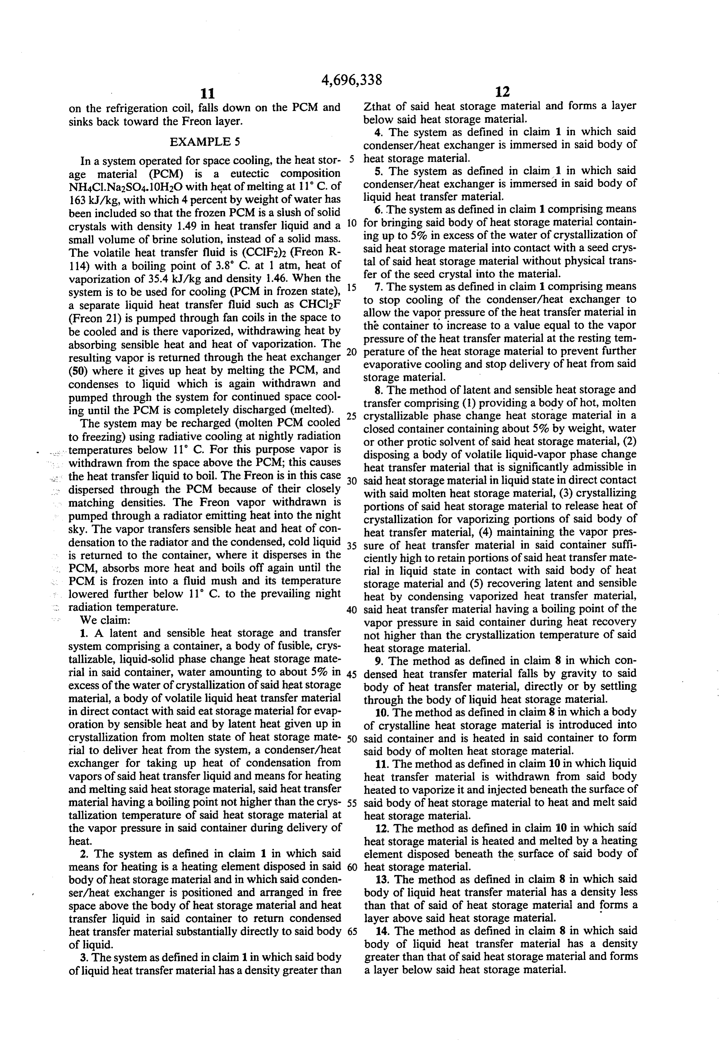
on the refrigeration coil, falls down on the PCM and Zthat of said heat storage material and forms a layer sinks back toward the Freon layer. below said heat storage material. 4. The system as defined in claim 1 in which said
EXAMPLE 5 condenser/heat exchanger is immersed in said body of
In a system operated for space cooling, the heat stor 5 heat storage material.
age material (PCM) is a eutectic composition 5. The system as defined in claim 1 in which said NH4CI.Na2SO4.10H2O with heat of melting at 11° C. of condenser/heat exchanger is immersed in said body of 163 kJ/kg, with which 4 percent by weight of water has liquid heat transfer material.
been included so that the frozen PCM is a slush of solid 6. The system as defined in claim 1 comprising means crystals with density 1.49 in heat transfer liquid and a 10 for bringing said body of heat storage material contain small volume of brine solution, instead of a solid mass. ing up to 5% in excess of the water of crystallization of The volatile heat transfer fluid is (CCIF2)2 (Freon R said heat storage material into contact with a seed crys 114) with a boiling point of 3.8 C. at 1 atm, heat of tal of said heat storage material without physical trans vaporization of 35.4 kJ/kg and density 1.46. When the 15 fer of the seed crystal into the material. system is to be used for cooling (PCM in frozen state), 7. The system as defined in claim 1 comprising means a separate liquid heat transfer fluid such as CHCl2F to stop cooling of the condenser/heat exchanger to (Freon 21) is pumped through fan coils in the space to allowcontainerthe vapor pressure of the heat transfer material in be cooled and is there vaporized, withdrawing heat by the to increase to a value equal to the vapor pressure of the heat transfer material at the resting ten absorbing sensible heat and heat of vaporization. The 20 perature of the heat storage material to prevent further resulting vapor is returned through the heat exchanger evaporative cooling and stop delivery of heat from said (50) where it gives up heat by melting the PCM, and storage material.
condenses to liquid which is again withdrawn and 8. The method of latent and sensible heat storage and pumped through the system for continued space cool transfer comprising (1) providing a body of hot, molten ing until the PCM is completely discharged (melted). 25 crystallizable phase change heat storage material in a The system may be recharged (molten PCM cooled closed container containing about 5% by weight, water to freezing) using radiative cooling at nightly radiation or other protic solvent of said heat storage material, (2) ... temperatures below 11° C. For this purpose vapor is disposing a body of volatile liquid-vapor phase change ... withdrawn from the space above the PCM; this causes heat transfer material that is significantly admissible in s the heat transfer liquid to boil. The Freon is in this case 30 said heat storage material in liquid state in direct contact dispersed through the PCM because of their closely with said molten heat storage material, (3) crystallizing matching densities. The Freon vapor withdrawn is portions of said heat storage material to release heat of pumped through a radiator emitting heat into the night crystallization for vaporizing portions of said body of sky. The vapor transfers sensible heat and heat of con heat transfer material, (4) maintaining the vapor pres densation to the radiator and the condensed, cold liquid 35 sure of heat transfer material in said container suffi is returned to the container, where it disperses in the ciently high to retain portions of said heat transfer mate PCM, absorbs more heat and boils off again until the rial in liquid state in contact with said body of heat PCM is frozen into a fluid mush and its temperature storage material and (5) recovering latent and sensible lowered further below 11° C. to the prevailing night heat by condensing vaporized heat transfer material, . . radiation temperature. 40 said heat transfer material having a boiling point of the We claim: vapor pressure in said container during heat recovery 1. A latent and sensible heat storage and transfer not higher than the crystallization temperature of said system comprising a container, a body of fusible, crys heat storage material.
tallizable, liquid-solid phase change heat storage mate 9. The method as defined in claim 8 in which con rial in said container, water amounting to about 5% in 45 densed heat transfer material falls by gravity to said excess of the water of crystallization of said heat storage body of heat transfer material, directly or by settling material, a body of volatile liquid heat transfer material through the body of liquid heat storage material. in direct contact with said eat storage material for evap 10. The method as defined in claim 8 in which a body oration by sensible heat and by latent heat given up in of crystalline heat storage material is introduced into crystallization from molten state of heat storage mate 50 said container and is heated in said container to form rial to deliver heat from the system, a condenser/heat said body of molten heat storage material. exchanger for taking up heat of condensation from 11. The method as defined in claim 10 in which liquid vapors of said heat transfer liquid and means for heating heat transfer material is withdrawn from said body and melting said heat storage material, said heat transfer heated to vaporize it and injected beneath the surface of material having a boiling point not higher than the crys 55 said body of heat storage material to heat and melt said tallization temperature of said heat storage material at heat storage material.
the vapor pressure in said container during delivery of 12. The method as defined in claim 10 in which said heat. heat storage material is heated and melted by a heating 2. The system as defined in claim 1 in which said element disposed beneath the surface of said body of means for heating is a heating element disposed in said 60 heat storage material.
body of heat storage material and in which said conden 13. The method as defined in claim 8 in which said ser/heat exchanger is positioned and arranged in free body of liquid heat transfer material has a density less space above the body of heat storage material and heat than that of said of heat storage material and forms a transfer liquid in said container to return condensed layer above said heat storage material. heat transfer material substantially directly to said body 65 14. The method as defined in claim 8 in which said of liquid. body of liquid heat transfer material has a density 3. The system as defined in claim 1 in which said body greater than that of said heat storage material and forms of liquid heat transfer material has a density greater than a layer below said heat storage material.
Page 10
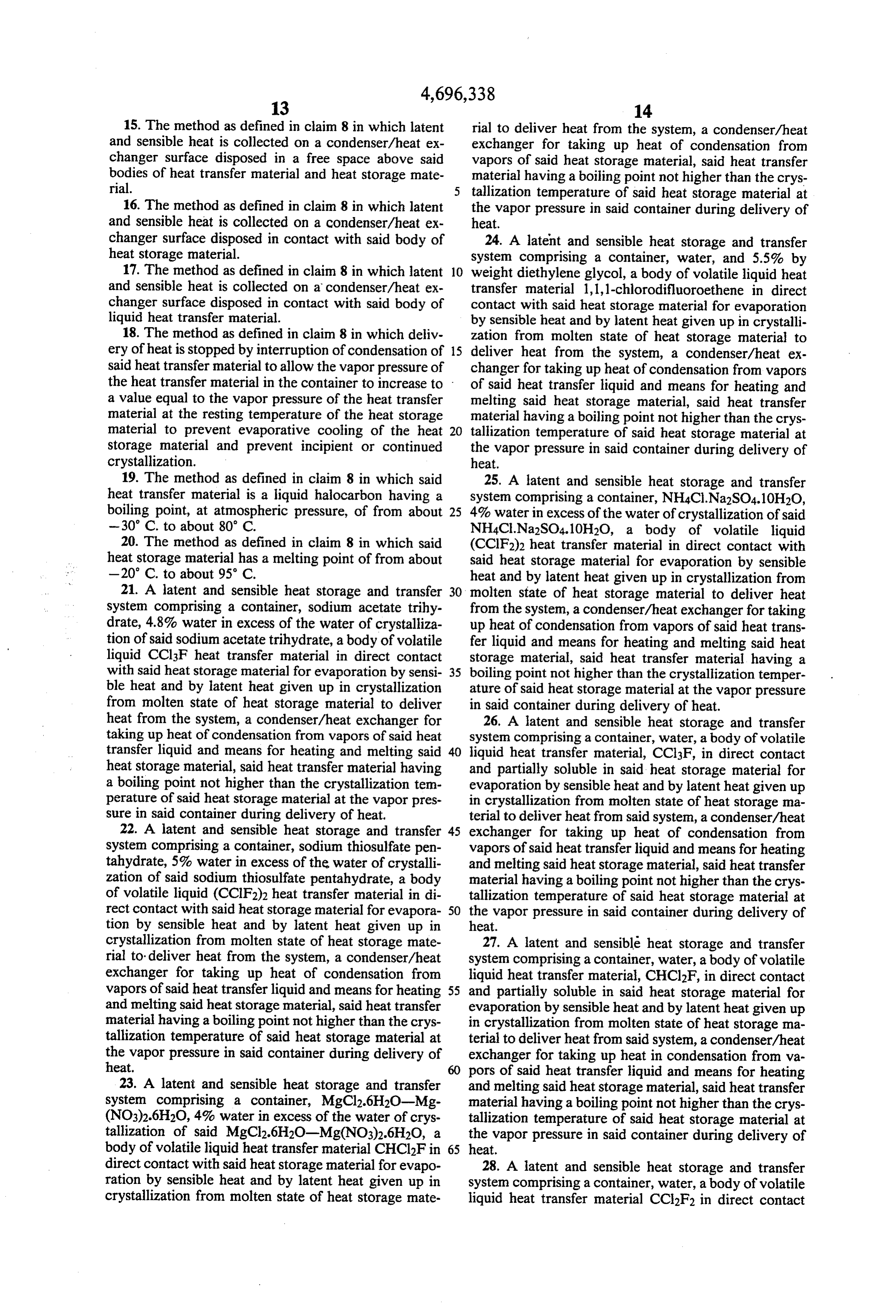
15. The method as defined in claim 8 in which latent rial to deliver heat from the system, a condenser/heat and sensible heat is collected on a condenser/heat ex exchanger for taking up heat of condensation from changer surface disposed in a free space above said vapors of said heat storage material, said heat transfer bodies of heat transfer material and heat storage mate material having a boiling point not higher than the crys rial. tallization temperature of said heat storage material at 16. The method as defined in claim 8 in which latent the vapor pressure in said container during delivery of and sensible heat is collected on a condenser/heat ex heat.
changer surface disposed in contact with said body of 24. A latent and sensible heat storage and transfer heat storage material. system comprising a container, water, and 5.5% by 17. The method as defined in claim 8 in which latent 10 weight diethylene glycol, a body of volatile liquid heat and sensible heat is collected on a condenser/heat ex transfer material 1,1,1-chlorodifluoroethene in direct changer surface disposed in contact with said body of contact with said heat storage material for evaporation liquid heat transfer material. by sensible heat and by latent heat given up in crystalli 18. The method as defined in claim 8 in which deliv zation from molten state of heat storage material to ery of heat is stopped by interruption of condensation of 15 deliver heat from the system, a condenser/heat ex said heat transfer material to allow the vapor pressure of changer for taking up heat of condensation from vapors the heat transfer material in the container to increase to of said heat transfer liquid and means for heating and a value equal to the vapor pressure of the heat transfer melting said heat storage material, said heat transfer material at the resting temperature of the heat storage material having a boiling point not higher than the crys material to prevent evaporative cooling of the heat 20 tallization temperature of said heat storage material at storage material and prevent incipient or continued the vapor pressure in said container during delivery of crystallization. heat.
19. The method as defined in claim 8 in which said 25. A latent and sensible heat storage and transfer heat transfer material is a liquid halocarbon having a system comprising a container, NH4C.Na2SO4.10H2O, boiling point, at atmospheric pressure, of from about 25 4% water in excess of the water of crystallization of said -30° C. to about 80 C. NH4Cl. Na2SO4.10H2O, a body of volatile liquid 20. The method as defined in claim 8 in which said (CClF2)2 heat transfer material in direct contact with heat storage material has a melting point of from about said heat storage material for evaporation by sensible -20 C. to about 95 C. heat and by latent heat given up in crystallization from 21. A latent and sensible heat storage and transfer 30 molten state of heat storage material to deliver heat system comprising a container, sodium acetate trihy from the system, a condenser/heat exchanger for taking drate, 4.8% water in excess of the water of crystalliza up heat of condensation from vapors of said heat trans tion of said sodium acetate trihydrate, a body of volatile fer liquid and means for heating and melting said heat liquid CCl3F heat transfer material in direct contact storage material, said heat transfer material having a with said heat storage material for evaporation by sensi 35 boiling point not higher than the crystallization temper ble heat and by latent heat given up in crystallization ature of said heat storage material at the vapor pressure from molten state of heat storage material to deliver in said container during delivery of heat. heat from the system, a condenser/heat exchanger for 26. A latent and sensible heat storage and transfer taking up heat of condensation from vapors of said heat system comprising a container, water, a body of volatile transfer liquid and means for heating and melting said 40 liquid heat transfer material, CCl3F, in direct contact heat storage material, said heat transfer material having and partially soluble in said heat storage material for a boiling point not higher than the crystallization tem evaporation by sensible heat and by latent heat given up perature of said heat storage material at the vapor pres in crystallization from molten state of heat storage ma sure in said container during delivery of heat. terial to deliver heat from said system, a condenser/heat 22. A latent and sensible heat storage and transfer 45 exchanger for taking up heat of condensation from system comprising a container, sodium thiosulfate pen vapors of said heat transfer liquid and means for heating tahydrate, 5% water in excess of the water of crystalli and melting said heat storage material, said heat transfer zation of said sodium thiosulfate pentahydrate, a body material having a boiling point not higher than the crys of volatile liquid (CClF2)2 heat transfer material in di tallization temperature of said heat storage material at rect contact with said heat storage material for evapora 50 the vapor pressure in said container during delivery of tion by sensible heat and by latent heat given up in heat.
crystallization from molten state of heat storage mate 27. A latent and sensible heat storage and transfer rial to deliver heat from the system, a condenser/heat system comprising a container, water, a body of volatile exchanger for taking up heat of condensation from liquid heat transfer material, CHCl2F, in direct contact vapors of said heat transfer liquid and means for heating 55 and partially soluble in said heat storage material for and melting said heat storage material, said heat transfer evaporation by sensible heat and by latent heat given up material having a boiling point not higher than the crys in crystallization from molten state of heat storage ma tallization temperature of said heat storage material at terial to deliver heat from said system, a condenser/heat the vapor pressure in said container during delivery of exchanger for taking up heat in condensation from va heat. 60 pors of said heat transfer liquid and means for heating 23. A latent and sensible heat storage and transfer and melting said heat storage material, said heat transfer system comprising a container, MgCl2.6H2O-Mg material having a boiling point not higher than the crys (NO3)2.6H2O, 4% water in excess of the water of crys tallization temperature of said heat storage material at tallization of said MgCl2.6H2O-Mg(NO3)2.6H2O, a the vapor pressure in said container during delivery of body of volatile liquid heat transfer material CHCl2F in 65 heat.
direct contact with said heat storage material for evapo 28. A latent and sensible heat storage and transfer ration by sensible heat and by latent heat given up in system comprising a container, water, a body of volatile crystallization from molten state of heat storage mate liquid heat transfer material CC2F2 in direct contact
Page 11
and partially soluble in said heat storage material for and melting said heat storage material, said heat transfer evaporation by sensible heat and by latent heat given up material having a boiling point not higher than the crys in crystallization from molten state of heat storage ma- tallization temperature of said heat storage material at terial to deliver heat from said system, a condenser/heat the vapor pressure in said container during delivery of exchanger for taking up heat of condensation from 5 heat.
vapors of said heat transfer liquid and means for heating k k is k
Page 12
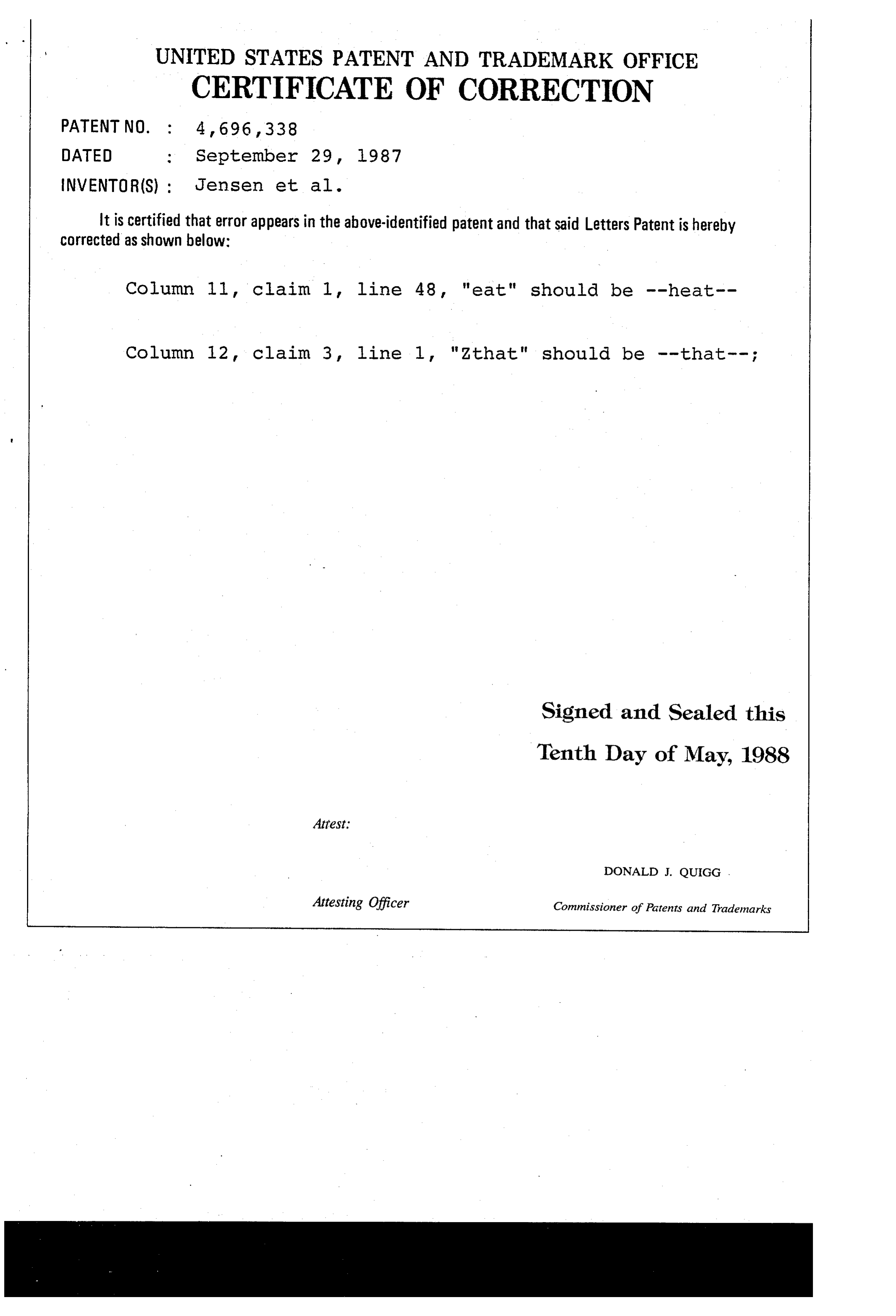
UNITED STATES PATENT AND TRADEMARK OFFICE
CERTIFICATE OF CORRECTION
NVENTOR(S) : Jensen et al.
It is certified that error appears in the above-identified patent and that said Letters Patent is hereby Corrected as shown below:
Column 11, claim 1, line 48, "eat" should be --heat
Column 12 claim 3, line 1, "Zthat" should be that; Signed and Sealed this
Tenth Day of May, 1988
DONALD J. QUIGG .
Attesting Officer Commissioner of Patents and Trademarks
Provenance
- Collection
- Cited prior art
- Original PDF
- patentimages.storage.googleapis.com →
- Filed
- 1985-03-06
- Pages
- 12
- Method
- pdftotext (the PDF's own text layer) + pdftoppm 300dpi page scans
- Source
- Google Patents bibliographic record
- Granted
- 1987-09-29
- Inventors
- Eric A. Jensen; James Hitchin; Albert G. Tsai; Gustaf O. Arrhenius; Thermal Energy Storage Inc
- Transcribed from
- patentimages.storage.googleapis.com →