patent · US4445566
Latent heat storage means
1 May 1984
Page 1 — bibliographic record
United States Patent (19) (11) 4,445,566 Laing et al. 45) May 1, 1984 54) LATENT HEAT STORAGE MEANS (56) References Cited 76) Inventors: Karsten Laing, Kaiserallee 51, 7500 U.S. PATENT DOCUMENTS Karlsruhe; Oliver Laing, 3,163,209 12/1964 Shinn .............................. 165/163 X Weissdornweg 14, 7400 Tibingen; 3,452,720 7/1969 Lawrence ... 165/10 X Inge Laing, Hofener Weg 35-37, 7148 3,485,216 12/1969 Lawrence ..... ... 165/10X Remseck 2, all of Fed. Rep. of 3,492,461 1/1970 Lawrence ..... ... 1650 X Germany 4,063,546 12/1977 Schmid et al..................... 165/10 X Primary Examiner-Albert W. Davis, Jr.
21 Appl. No.: 358,809 Attorney, Agent, or Firm-Pennie & Edmonds 22 Filed: Mar. 16, 1982 57 ABSTRACT (30) Foreign Application Priority Data Latent heat storage means having, fusible at a pre-deter mined temperature, a mass which is traversed by heat
Mar. 16, 1981 ICH. Switzerland ......................... 1754/81 exchanger surfaces and which fills a container jointly with the heat exchanger, characterized in that the con 51) Int. Cl. .............................................. F28D 17/00 tainer is constructed as a cylindrical vessel while the 52 U.S.C. ................................... 165/10; 165/11 R; heat exchangers are formed from elongated strips 165/109 R; 165/104.11 wound spirally about a vertical axis.
58) Field of Search ...................... 165/10, 104.11, 11,
Page 2
Drawing sheet — no readable text.
Page 3
Drawing sheet — no readable text.
Page 4
connect with each other at the center of the vessel with
LATENT HEAT STORAGE MEANS the total number of entering spirals equating the total number of exiting spirals such that the total number of
FIELD OF THE INVENTION spirals is an even number. As a result, the temperature The invention relates to latent heat starage means in of the heat conveyor in the entering spirals diminishes which the storage mass is accommodated by containers from the periphery towards the centre, while in the case which are traversed by large-area hollow bodies of the exiting spirals the temperature drops from the through which flow heat carrier means. centre towards the periphery. The spiral of storage BACKGROUND OF THE INVENTION mass enclosed between an entering and an exiting spiral 10 therefore undergoes more or less the same accretional
Known latent heat storage means suffer from the dissipation of heat at every point along its length, so that drawback that their capacity diminishes with the num always the total surface area of the heat conveyor par ber of charging cycles and is finally lost completely, ticipates in the heat exchange.
since the seed crystals stratify. Therefore, constructions Since the adhesion of the crystalline storage mass on have been devised in which crystallisation takes place 15 the heat exchanger surfaces is interrupted directly after on the surface of rotary tube heat conveyors so that a absorption of the charge, due to formation of a fusion constant recirculation of the molten mixture is assured layer, the forces feared cannot develop due to localised and stratification of the seed crystals is obviated. increase in volume, because the excess molten mixture Furthermore, latent heat storage means have become rises along the heat exchanger surfaces and collects on known wherein stratification is prevented by motor 20 them.
driven agitators. The incorporation of motor driven recirculating devices into the storage means construc theAccording to the invention, therefore, the walls of tion results in a constant consumption of driving en extend vertically. are hollow bodies
The disposed in such a way that they excess molten mixture arising ergy.
25 from the increase in volume therefore rises upwardly. It
DESCRIPTION OF THE INVENTION is possible according to the invention to dispose there a diaphragm
Furthermore, methods have become known which filled with the of elastic material which separates the space make possible a static construction of the storage means with gas. storage mass from a space which is filled by using thickening substances to fix regularly disperse This diaphragm can therefore yield within the frame seed crystals in the molten mixture. Since, however, 30 work of the volumetric increase. Since the volume differences in density constantly exist between the crys talline and the molten state, in the event of variations in extent, theforgasthe available enclosed gas diminishes to the same pressure in this space rises as the charge volume, there act on the walls of the container and in particular also on the heat conveyor elements forces increases. This process occurs at a constant tempera which can result in deformation and in the long run 35 increaseture, namely the fusion temperature, so that the pressure destruction, because by virtue of the increase in volume is a direct measure of the state of charge. upon fusion of the previously crystalline storage mass, The system described is suitable for all storage masses zones occur in which extremely high pressures can in which differences in density of the components of the build up. The forces which are thus occasioned distort storage mass do not result in segregation. If, on the both the container wall and also the heat conveyors. In other hand, it is intended to use storage masses which contrast to heating systems, the part of the molten mass have a tendency to separate, then a further problem is which goes beyond the starting volume cannot be intro that of conveying the heavier layers of the molten mix duced into high containers, because it would freeze. ture into the highest lightest layers of the separated When shrinkage occurs during crystallisation resulting molten mixture, resulting in the desired re-mixture. from heat withdrawal, cavities occur in the storage 45 To this end, the invention utilises the difference in mass which in turn lead to uncontrollable stresses due to density between the molten mixture and the crystalline the action of atmospheric pressure. phase. In the case of storage masses which have low Finally, no method has as yet come to light by which viscosity mixtures, after fusion of the storage mass, the it is possible to indicate the state of charge without any difference in temperature between the odd and the considerable complication. Regulation of the energy 50 cooler even spirals results in all areas of the container in source, e.g. the heat pump as a function of the state of a torroidal flow which leads to an intimate re-mixture of charge is, however, a vital prerequisite in the avoidance the entire molten mass.
of harmful over-heating and for any economic storage In the case of storage masses, the melt of which has a means operation. high viscosity, according to the invention, a second The invention indicates a way by which the aforesaid 55 horizontally extending heat conveyor at the bottom of drawbacks can be avoided. The invention provides for the container prededes the heat conveying spiral hollow mass-filled storage tanks. According to the invention, members and is therefore traversed by the hottest heat these are constructed as cylindrical vessels, the weight conveyor during charging. Both these heat conveyors of which allows them to be carried one at a time even are therefore traversed by the heat carrier in such a way up staircases and into cellars. At the erection site, they 60 that fusion occurs in the highest area of the crystalline can then be combined to form storage columns. In such mass but only after a considerable part of the storage a vessel there is a large-area hollow body traversed by mass in the lower area has already been fused. As a a heat carrier and which serves as a heat conveyor result of this arrangement, during charging of the stor traversing the storage mass at specific intervals and age means, a relatively thick molten zone develops being constructed in the form of spirals with a vertically 65 below the crystalline spiral body of storage mass which extending axis. The invention provides for the hollow is still cohesive in the upper zone of the spiral heat body heat conveyors to be in the form of converging conveyor, resulting in molten zones which become entering spirals and diverging exiting spirals which increasingly thinner from the bottom upwards as they
Page 5
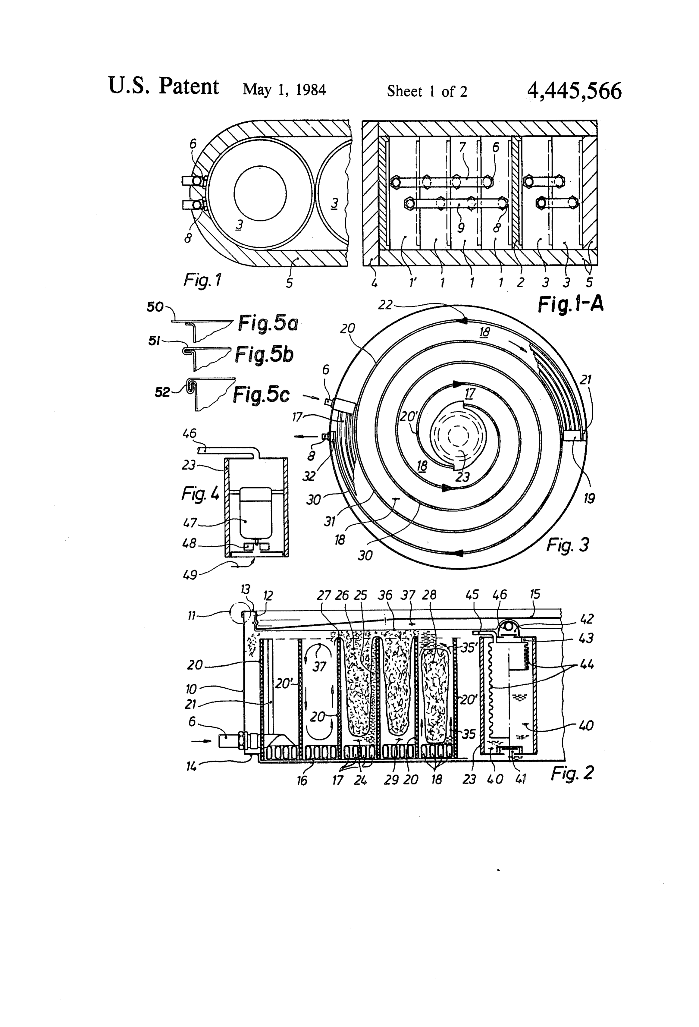
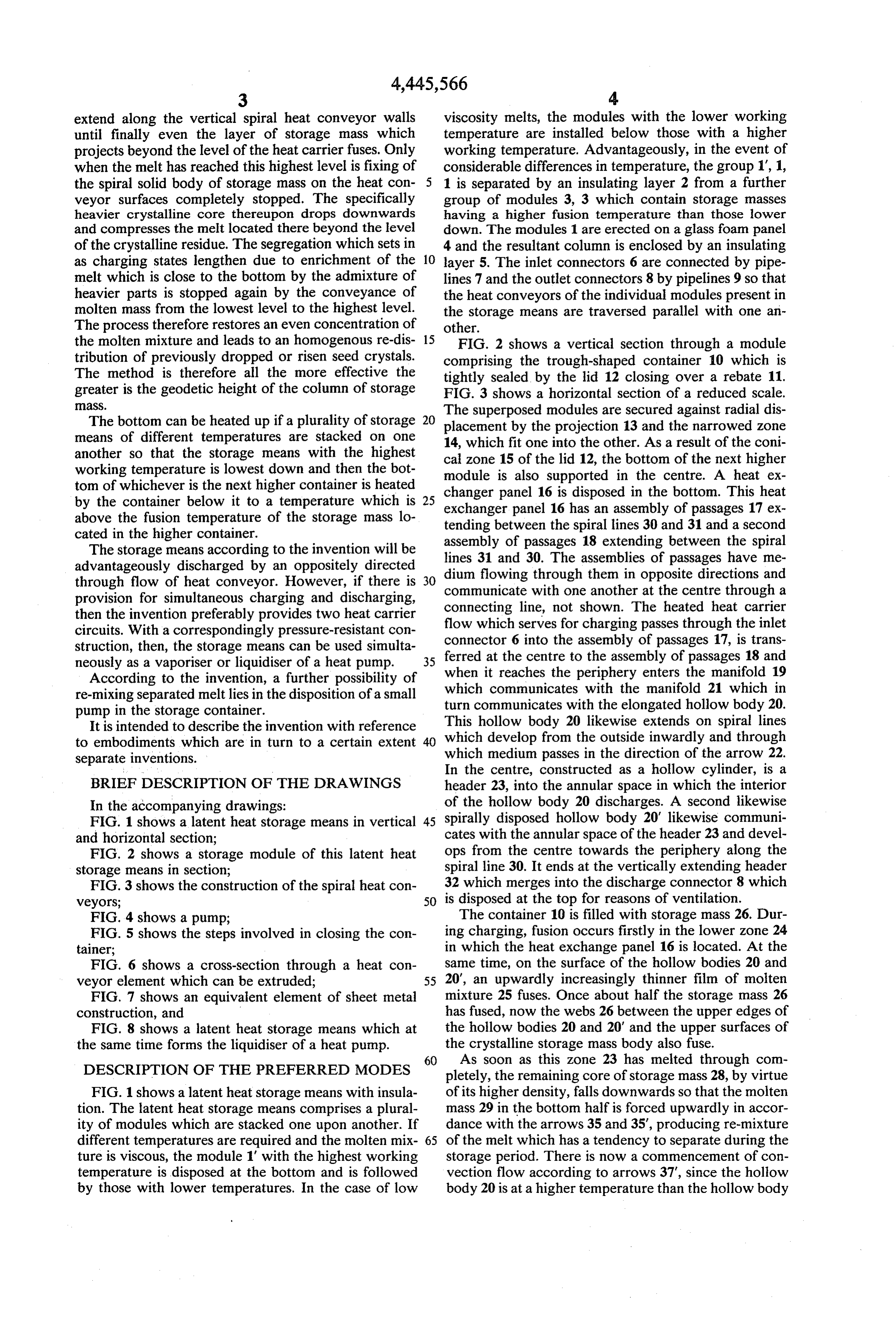
extend along the vertical spiral heat conveyor walls viscosity melts, the modules with the lower working until finally even the layer of storage mass which temperature are installed below those with a higher projects beyond the level of the heat carrier fuses. Only working temperature. Advantageously, in the event of when the melt has reached this highest level is fixing of considerable differences in temperature, the group 1, 1, the spiral solid body of storage mass on the heat con 5 1 is separated by an insulating layer 2 from a further veyor surfaces completely stopped. The specifically group of modules 3, 3 which contain storage masses heavier crystalline core thereupon drops downwards having a higher fusion temperature than those lower and compresses the melt located there beyond the level down. The modules 1 are erected on a glass foam panel of the crystalline residue. The segregation which sets in 4 and the resultant column is enclosed by an insulating as charging states lengthen due to enrichment of the 10 layer 5. The inlet connectors 6 are connected by pipe melt which is close to the bottom by the admixture of lines 7 and the outlet connectors 8 by pipelines 9 so that heavier parts is stopped again by the conveyance of the heat conveyors of the individual modules present in molten mass from the lowest level to the highest level. the storage means are traversed parallel with one an The process therefore restores an even concentration of other.
the molten mixture and leads to an homogenous re-dis 15 FIG. 2 shows a vertical section through a module tribution of previously dropped or risen seed crystals. comprising the trough-shaped container 10 which is The method is therefore all the more effective the greater is the geodetic height of the column of storage tightly sealed by the lid 12 closing over a rebate 11. FIG. 3 shows a horizontal section of a reduced scale.
The bottom can be heated up if a plurality of storage 20 The superposed modules are secured against radial dis
placement by the projection 13 and the narrowed Zone means of different temperatures are stacked on one 14, which fit one into the other. As a result of the coni another so that the storage means with the highest cal zone 15 of the lid 12, the bottom of the next higher working temperature is lowest down and then the bot module tom of whichever is the next higher container is heated changer ispanelalso supported in the centre. A heat ex by the container below it to a temperature which is 25 exchanger panel1616is has disposed in the bottom. This heat an assembly of passages 17 ex above the fusion temperature of the storage mass lo tending between the spiral lines 30 and 31 and a second cated in the higher container.
The storage means according to the invention will be lines 31 and 30. The assemblies of between assembly of passages 18 extending passages the spiral have me advantageously discharged by an oppositely directed dium flowing through then in opposite directions and through flow of heat conveyor. However, if there is communicate with one another at the centre through
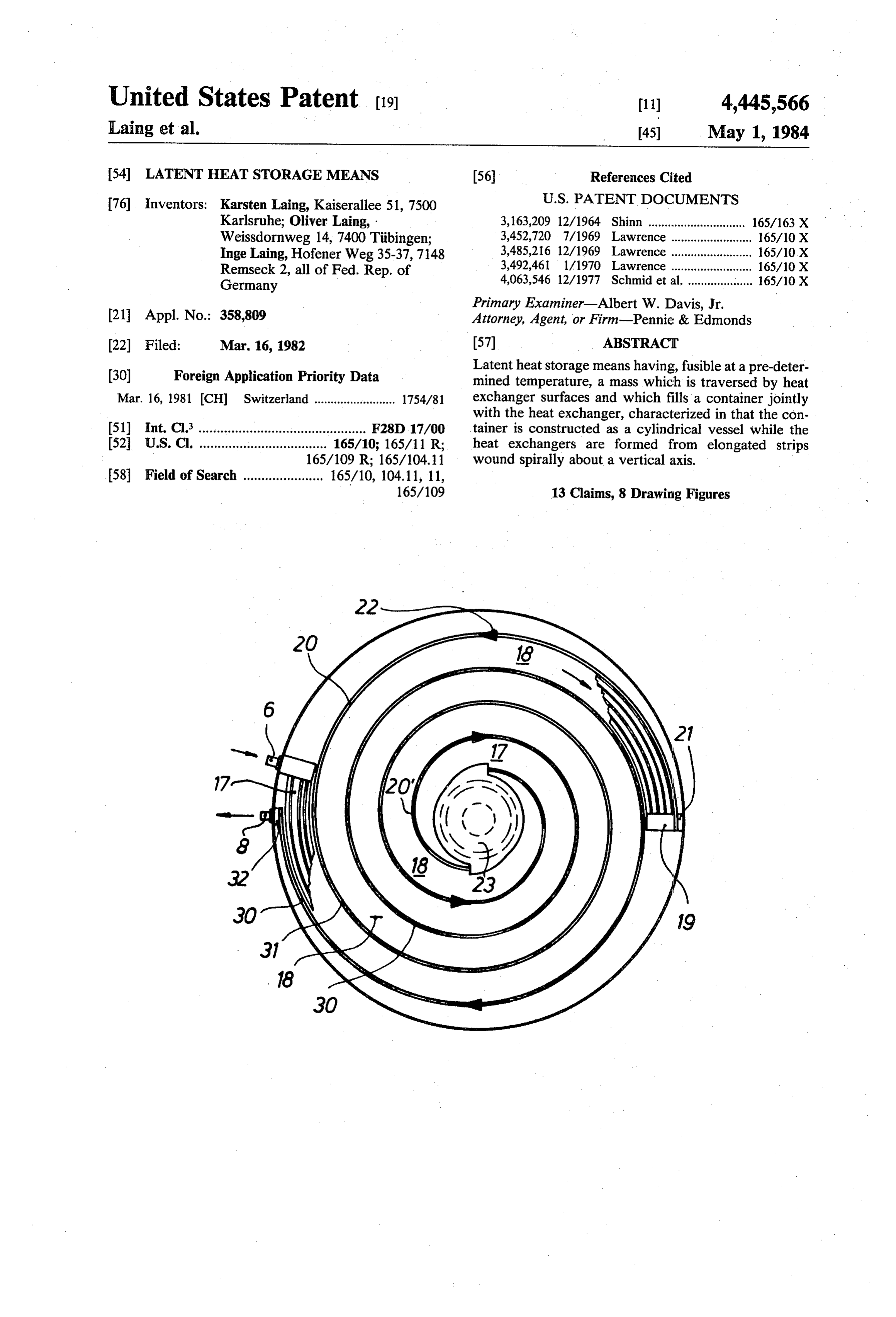
provision for simultaneous charging and discharging, connecting line, not shown. The heated heat carriera then the invention preferably provides two heat carrier flow which serves for charging passes through the inlet circuits. With a correspondingly pressure-resistant con struction, then, the storage means can be used simulta connector 6 into the assembly of passages 17, is trans neously as a vaporiser or liquidiser of a heat pump. 35 ferred at the centre to the assembly of passages 18 and According to the invention, a further possibility of when it reaches the periphery enters the manifold 19 re-mixing separated melt lies in the disposition of a small which communicates with the manifold 21 which in pump in the storage container. turn communicates with the elongated hollow body 20. It is intended to describe the invention with reference This hollow body 20 likewise extends on spiral lines to embodiments which are in turn to a certain extent 40 which develop from the outside inwardly and through separate inventions. which medium passes in the direction of the arrow 22. In the centre, constructed as a hollow cylinder, is a
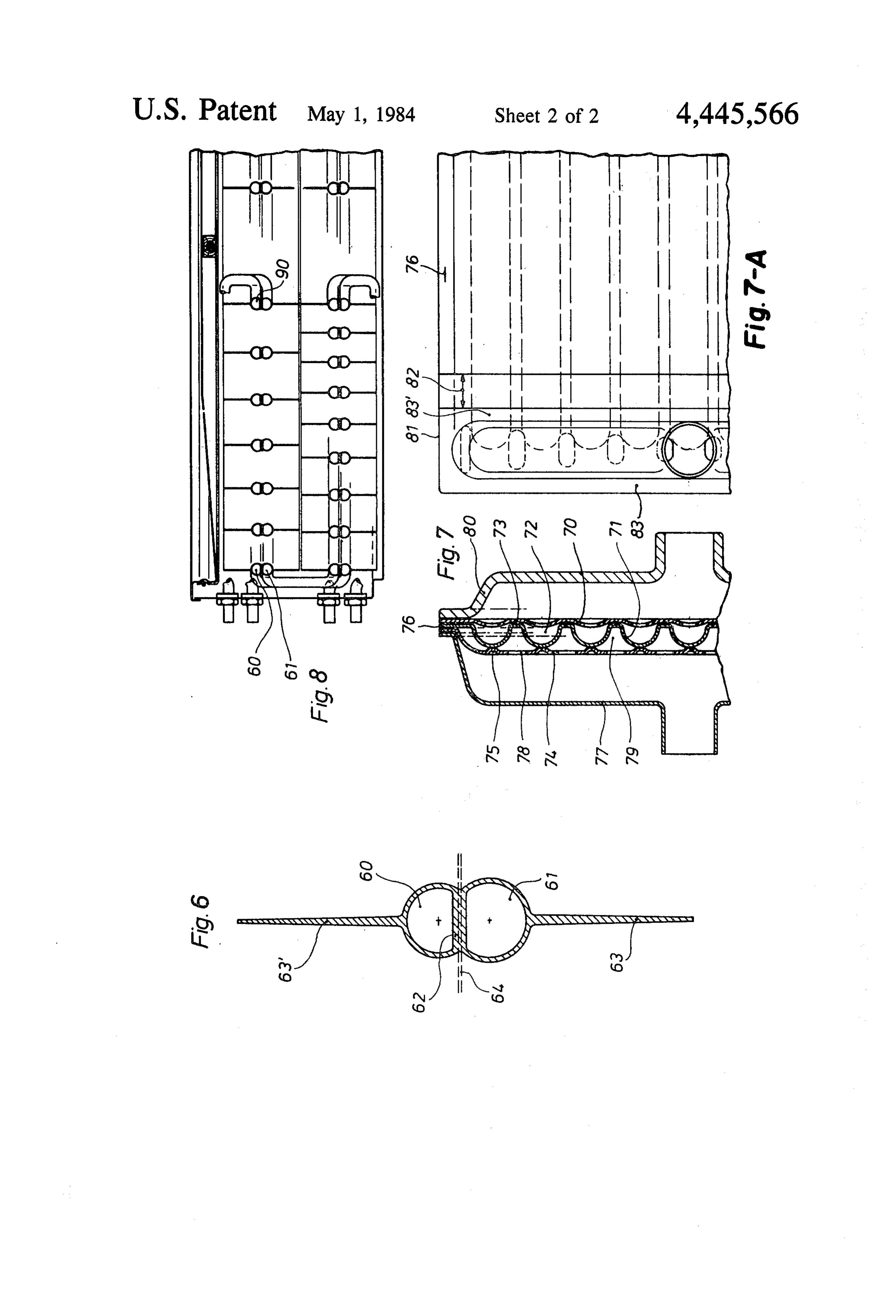
BRIEF DESCRIPTION OF THE DRAWINGS header 23, into the annular space in which the interior In the accompanying drawings: of the hollow body 20 discharges. A second likewise FIG. 1 shows a latent heat storage means in vertical 45 spirally disposed hollow body 20' likewise communi and horizontal section; cates with the annular space of the header 23 and devel FIG. 2 shows a storage module of this latent heat ops from the centre towards the periphery along the storage means in section; spiral line 30. It ends at the vertically extending header FIG. 3 shows the construction of the spiral heat con 32 which merges into the discharge connector 8 which veyors; SO is disposed at the top for reasons of ventilation. FIG. 4 shows a pump; The container 10 is filled with storage mass 26. Dur FIG. 5 shows the steps involved in closing the con ing charging, fusion occurs firstly in the lower zone 24 tainer; in which the heat exchange panel 16 is located. At the FIG. 6 shows a cross-section through a heat con same time, on the surface of the hollow bodies 20 and veyor element which can be extruded; 55 20', an upwardly increasingly thinner film of molten FIG. 7 shows an equivalent element of sheet metal mixture 25 fuses. Once about half the storage mass 26 construction, and has fused, now the webs 26 between the upper edges of FIG. 8 shows a latent heat storage means which at the hollow bodies 20 and 20' and the upper surfaces of the same time forms the liquidiser of a heat pump. the crystalline storage mass body also fuse. 60 As soon as this zone 23 has melted through con
DESCRIPTION OF THE PREFERRED MODES pletely, the remaining core of storage mass 28, by virtue FIG. 1 shows a latent heat storage means with insula of its higher density, falls downwards so that the molten tion. The latent heat storage means comprises a plural mass 29 in the bottom half is forced upwardly in accor ity of modules which are stacked one upon another. If dance with the arrows 35 and 35", producing re-mixture different temperatures are required and the molten mix 65 of the melt which has a tendency to separate during the ture is viscous, the module 1" with the highest working storage period. There is now a commencement of con temperature is disposed at the bottom and is followed vection flow according to arrows 37", since the hollow by those with lower temperatures. In the case of low body 20 is at a higher temperature than the hollow body
Page 6
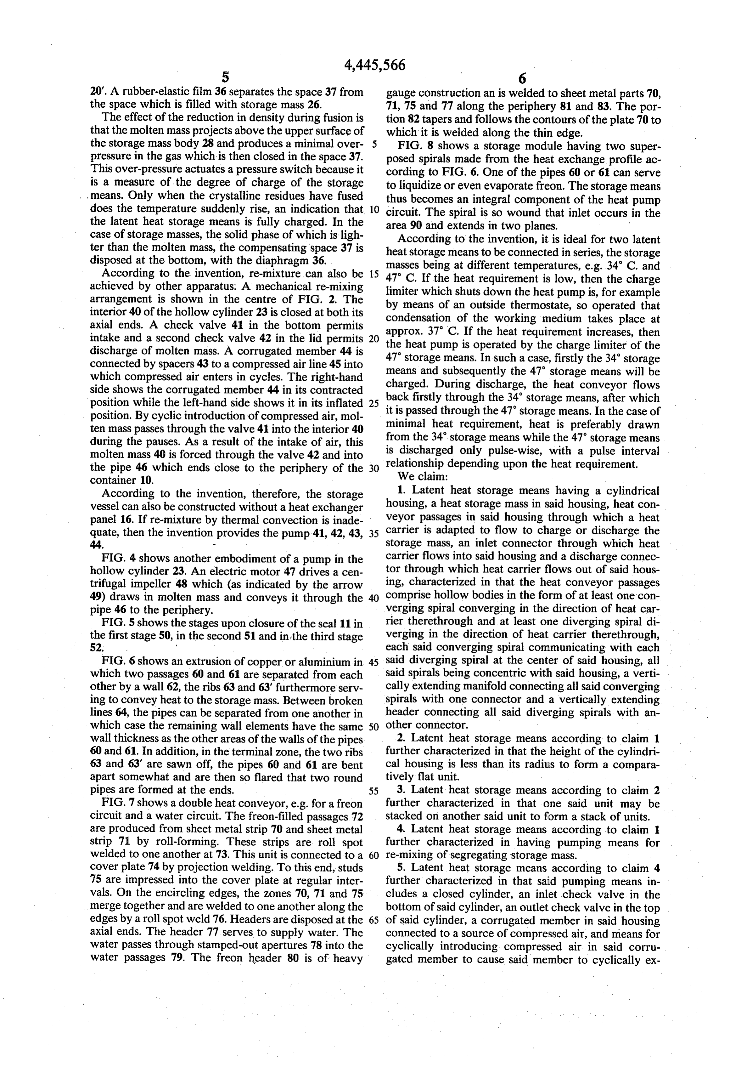
20'. A rubber-elastic film 36 separates the space 37 from gauge construction an is welded to sheet metal parts 70, the space which is filled with storage mass 26. 71, 75 and 77 along the periphery 81 and 83. The por The effect of the reduction in density during fusion is tion 82 tapers and follows the contours of the plate 70 to that the molten mass projects above the upper surface of which it is welded along the thin edge. the storage mass body 28 and produces a minimal over FIG. 8 shows a storage module having two super pressure in the gas which is then closed in the space 37. posed spirals made from the heat exchange profile ac This over-pressure actuates a pressure switch because it cording to FIG. 6. One of the pipes 60 or 61 can serve is a measure of the degree of charge of the storage to liquidize or even evaporate freon. The storage means means. Only when the crystalline residues have fused thus becomes an integral component of the heat pump does the temperature suddenly rise, an indication that 10 circuit. The spiral is so wound that inlet occurs in the the latent heat storage means is fully charged. In the area 90 and extends in two planes.
case of storage masses, the solid phase of which is ligh According to the invention, it is ideal for two latent ter than the molten mass, the compensating space 37 is heat storage means to be connected in series, the storage disposed at the bottom, with the diaphragm 36.
According to the invention, re-mixture can also be 47 C. Ifbeing
masses at different temperatures, e.g. 34 C. and achieved by other apparatus. A mechanical re-mixing limiter which shutsrequirement the heat down the is low, then the charge heat pump is, for example arrangement is shown in the centre of FIG. 2. The by means of an outside thermostate, interior 40 of the hollow cylinder 23 is closed at both its condensation of the working mediumso takes operated that place at axial ends. A check valve 41 in the bottom permits approx. 37 C. If the heat requirement increases, intake and a second check valve 42 in the lid permits 20 the heat pump is operated by the charge limiter ofthen the discharge of molten mass. A corrugated member 44 is 47 storage means. In such a case, firstly the 34 storage connected by spacers 43 to a compressed airline 45 into means and subsequently the 47 storage means will be which compressed air enters in cycles. The right-hand charged. During discharge, the heat conveyor flows side shows the corrugated member 44 in its contracted position while the left-hand side shows it in its inflated 25 back
firstly through the 34 storage means, after which passed through the 47 storage means. In the case of position. By cyclic introduction of compressed air, mol minimal heat requirement, heat is preferably drawn ten mass passes through the valve 41 into the interior 40 from the 34 storage means while the 47 storage means during the pauses. As a result of the intake of air, this is discharged only pulse-wise, molten mass 40 is forced through the valve 42 and into relationship depending upon the with heat a pulse interval requirement.
the pipe 46 which ends close to the periphery of the 30
We claim:
container 10.
According to the invention, therefore, the storage 1. Latent heat storage means having a cylindrical vessel can also be constructed without a heat exchanger housing, a heat storage mass in said housing, heat con panel 16. If re-mixture by thermal convection is inade veyor passages in said housing through which a heat quate, then the invention provides the pump 41, 42, 43, 35 carrier is adapted to flow to charge or discharge the 44. - storage mass, an inlet connector through which heat FIG. 4 shows another embodiment of a pump in the carrier flows into said housing and a discharge connec hollow cylinder 23. An electric motor 47 drives a cen tor through which heat carrier flows out of said hous trifugal impeller 48 which (as indicated by the arrow ing, characterized in that the heat conveyor passages 49) draws in molten mass and conveys it through the comprise hollow bodies in the form of at least one con pipe 46 to the periphery. verging spiral converging in the direction of heat car FIG. 5 shows the stages upon closure of the seal 11 in rier therethrough and at least one diverging spiral di the first stage 50, in the second 51 and in the third stage verging in the direction of heat carrier therethrough, 52. each said converging spiral communicating with each FIG. 6 shows an extrusion of copper or aluminium in 45 said diverging spiral at the center of said housing, all which two passages 60 and 61 are separated from each said spirals being concentric with said housing, a verti other by a wall 62, the ribs 63 and 63' furthermore serv cally extending manifold connecting all said converging ing to convey heat to the storage mass. Between broken spirals with one connector and a vertically extending lines 64, the pipes can be separated from one another in header connecting all said diverging spirals with an which case the remaining wall elements have the same 50 other connector.
wall thickness as the other areas of the walls of the pipes 2. Latent heat storage means according to claim 1 60 and 61. In addition, in the terminal zone, the two ribs further characterized in that the height of the cylindri 63 and 63' are sawn off, the pipes 60 and 61 are bent cal housing is less than its radius to form a compara apart somewhat and are then so flared that two round tively flat unit.
pipes are formed at the ends. 55 3. Latent heat storage means according to claim 2 FIG. 7 shows a double heat conveyor, e.g. for a freon further characterized in that one said unit may be circuit and a water circuit. The freon-filled passages 72 stacked on another said unit to form a stack of units. are produced from sheet metal strip 70 and sheet metal 4. Latent heat storage means according to claim 1 strip 71 by roll-forming. These strips are roll spot further characterized in having pumping means for welded to one another at 73. This unit is connected to a 60 re-mixing of segregating storage mass. cover plate 74 by projection welding. To this end, studs 5. Latent heat storage means according to claim 4 75 are impressed into the cover plate at regular inter further characterized in that said pumping means in vals. On the encircling edges, the zones 70, 71 and 75 cludes a closed cylinder, an inlet check valve in the merge together and are welded to one another along the bottom of said cylinder, an outlet check valve in the top edges by a roll spot weld 76. Headers are disposed at the 65 of said cylinder, a corrugated member in said housing axial ends. The header 77 serves to supply water. The connected to a source of compressed air, and means for water passes through stamped-out apertures 78 into the cyclically introducing compressed air in said corru water passages 79. The freon header 80 is of heavy gated member to cause said member to cyclically ex
Page 7
pand and contract to impart a pumping action within 10. Latent heat storage means according to claim 9 said cylinder. further characterized in that said conveyor passages 6. Latent heat storage means according to claim 1 form two groups.
further characterized in that said pump means com further 11. Latent heat storage means according to claim 10 prises a centrifugal impeller. characterized in that the two groups of passages 7. Latent heat storage means according to claim 4 are separated by a wall the thickness of which is at least further characterized in that a further heat conveyor is twice as great as the wall thickness of the passages. 12. Latent heat storage means according to claim 10 positioned at the bottom of said housing. further characterized in that a first group of passages 8. Latent heat storage means according to claim 4 10 comprises plates connected to one another by welded further characterized in that said pump means conveys seams and a second group comprises plates connected molten storage mass over the vertical extent of the to one another by projection welds. housing. 13. Latent heat storage means according to claim 1 9. Latent heat stroage means according to claim 1 further characterized in having a gas filled space in said further characterized in that said heat conveyor pas 15 housing including a pressure sensitive switch for indi sages comprise an extruded profile having a plurality of cating when said storage
mass khasis become charged.
passages therein.
Provenance
- Collection
- Cited prior art
- Original PDF
- patentimages.storage.googleapis.com →
- Filed
- 1982-03-16
- Pages
- 7
- Method
- pdftotext (the PDF's own text layer) + pdftoppm 300dpi page scans
- Source
- Google Patents bibliographic record
- Granted
- 1984-05-01
- Inventors
- Karsten Laing; Oliver Laing; Inge Laing
- Transcribed from
- patentimages.storage.googleapis.com →