patent · US4154292
Heat exchange method and device therefor for thermal energy storage
15 May 1979
Page 1 — bibliographic record
United States Patent (19) 11) 4,154,292 Herrick 45 May 15, 1979 (54) HEAT EXCHANGEMETHOD AND DEVICE Potential Heat, Canadian Journal of Technology, vol. THEREFOR FORTHERMAL ENERGY 33, p. 293, 1955.
STORAGE Whillier, A. Letter to the Editor, The Sun at Work, vol. 75 Inventor: Carlyle S. Herrick, Alplaus, N.Y. 2, p. 2, 6/1957.
Telbes, M. Solar-Heat Storage, ASME Paper 64 73 Assignee: General Electric Company, Wa-SOL-9, p. 4, 12/1964. Schenectady, N.Y.
21 Appl. No.: 868,532 Primary Examiner-Albert W. Davis, Jr. 22 Filed: Jan. 11, 1978 Attorney, Agent, or Firm-Leo I. Malossi; Joseph T. Cohen; Charles T. Watts
Related U.S. Application Data 63 Continuation-in-part of Ser. No. 706,875, Jul. 19, 1976, 57 ABSTRACT abandoned. A heat exchange device for the introduction of thermal 51) Int. C.’.............................................. F28D 21/00 energy into and removal of thermal energy from liquid 52 U.S. C. ........................................... 165/1; 62/59; solid phase change material is described in which the 126/400; 165/104 S; 237/1 A phase change material is maintained in a container, 58 Field of Search .................... 165/104 S; 126/400; which is slowly rotated about a generally horizontal -- 62/59, 345, 346; 237/1 A axis at a substantially constant rotational speed. Means 56) References Cited are provided for automatically nucleating the phase change material as required for cyclic operation. The
2,677,243 5/1954 Telbes .......................... 165/104 S X ently melting hydrates for the storage of thermal en 3,668,886 6/1972 Hofer ..................................... 62/346 ergy.
OTHER PUBLICATIONS
Hodgins et al., J. W. The Storage and Transfer of Low 26 Claims, 11 Drawing Figures
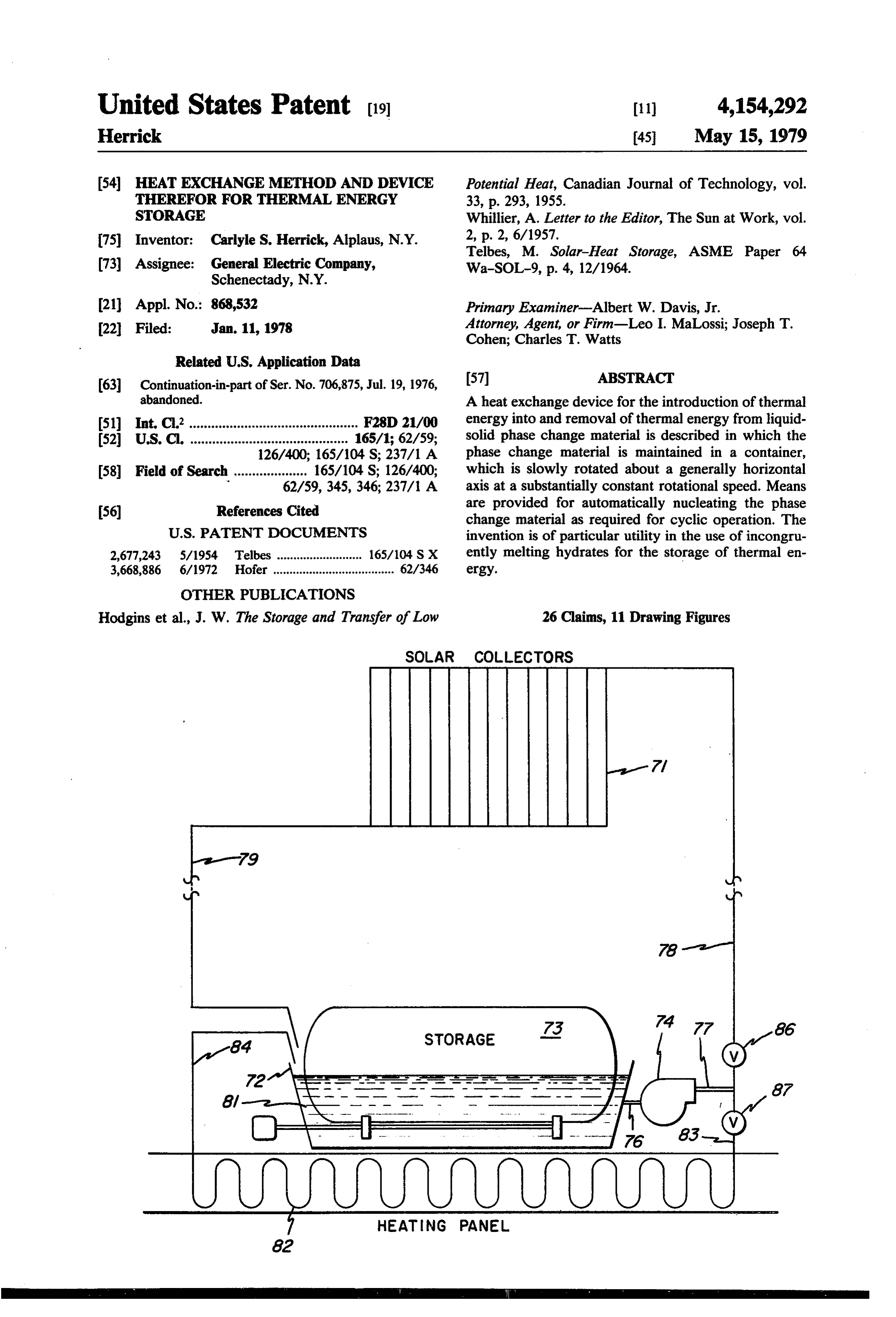
SOLAR COLLECTORS
HEATNG PANEL
Page 2
Drawing sheet — no readable text.
Page 3
Drawing sheet — no readable text.
Page 4
Drawing sheet — no readable text.
Page 5
Drawing sheet — no readable text.
Page 6
Drawing sheet — no readable text.
Page 7
Drawing sheet — no readable text.
Page 8
is to be introduced into or removed from Glauber's salt,
HEAT EXCHANGEMETHOD AND DEVICE movement of the heat transfer surface relative to the THEREFOR FOR THERMAL ENERGY STORAGE solution is of no advantage. The problem with respect
BACKGROUND OF THE INVENTION
to macro-segregation still occurred in the Hodgins et al.
5 apparatus (p. 298). It is reported therein that crystalliza
This is a continuation-in-part of U.S. Pat. application tion occurred at the bottom of the container for the salt Ser. No. 706,875 filed July 19, 1976, now abandoned, in solution. A layer of hydrated crystals formed an imper the name of Carlyle S. Herrick. vious barrier over a layer of the anhydrous salt, thereby The present invention is directed to the storage of preventing the anhydrous salt so crystallized from en thermal energy in liquid-solid phase change materials O tering into the requisite hydration reaction. This isola and improved devices and methods therefor. tion of the anhydrous layer from the solution prevents The need for energy Storage is dictated by the fact dissolution of the anhydrous material, which must pre that the demand for energy and the supply of energy cede crystallization of additional Na2SO410H20, both vary with time and generally this demand and thereby limiting in practice the amount of latent heat supply are not synchronous. In the past centruy this 15 that is available in theory.
lack of synchronization has been met by a reliance on In a Letter to the Editor (The Sun at Work, Vol. 2, p. fossil fuels. These fuels are becoming increasingly 2, June 1957) A. Whillier makes reference to the work scarce and expensive and as a result, intensive effort is by Hodgin et al. and proposes to overcome the problem being directed toward the development of alternate of stratification by providing for continuously mechani primary energy sources, such as solar energy. The ef 20 cally inverting containers of salts possessing noncon fective utilization of solar energy requires the develop gruent melting points. The arrangement proposed for ment of new mechanisms and processes for energy stor accomplishing this is to "mount the chemical containers age, since solar energy is by nature only intermittently on a wheel which would be rotated slowly during the available. cooling cycle'. Thus, if the containers were sealed and Information on thermal energy storage as presently 25 fixed in place, each container on the rotating wheel understood including historical aspects of some of the would periodically be turned upside down and then developments is set forth in the report "The Status of right side up.
Thermal Energy Storage" by F. P. Bundy, C. S. Her On page 4 of the article "Solar-Heat Storage' by rick, and P. G. Kosky (General Electric Technical Maria Telkes (ASME Paper 64 WA-SOL-9) reference Information Series Report 76CRDO41 April, 1976). 30 is made to the work by Hodgins et al. and to Whillier The reviews therein of thermal energy storage (TES) correspondence with the comment that "Such mixing, include a discussion of the basic parameters in liquid stirring or agitating is highly impractical, especially in sensible heat storage, solid sensible heat storage and sealed containers...'. The author proceeds to describe a phase change (liquid to solid) latent heat storage. Table mechanism to prevent the settling of the anhydrous salt; II therein (page 78 et seq.) sets forth a listing of a large 35 namely, the mixing of thickeners with the salt hydrate number of heat of fusion materials from which selec to change it into a gel upon melting. tions may be made for the practice of the instant inven The instant invention has particular application to tion. The Bundy et al. publication is incorporated by overcoming the long existing problem in utilizing Glau reference. ber's salt and similar incongruently melting hydrate A study of the binary inorganic salt hydrates together systems, and also to the provision of apparatus and the with guidelines for the selection thereof for TES is set method for economically and effectively providing for forth in the publication "Thermochemistry of Salt Hy heat transfer into and out of liquid-solid phase change drates' by G. Belton and F. Ajami (NTIS PB-227966 materials in general.
May 1973). This study is also incorporated by reference. DESCRIPTION OF THE INVENTION The problem of macro-segregation that is encoun 45 tered in incongruently melting salt hydrates is referred A heat exchange device for the introduction of ther to on page 56 of the Belton et al. report. An attempt was mal energy into and removal of thermal energy from made to overcome this problem by J. W. Hodgins and liquid-solid phase change material is described in which T. W. Hoffman as described in their paper "The Stor the phase change material is maintained in a container, age and Transfer of Low Potential Heat', Canadian 50 which is slowly rotated about a generally horizontal Journal of Technology 33, 293 (1955). The article is axis at a substantially constant rotational speed to im directly concerned with the use of Glauber's salt (Na2 part interparticle motion to crystallized material when SO4.10H20), which stores nearly five times as much present. Means are provided for automatically nucleat heat as an equal volume of water in the 80-100' F. ing the phase change material as required for cyclic range. In an attempt to overcome the problem encoun 55 operation. The invention is of particular utility in the tered with the incongruent melting of Glauber's salt, the use of incongruently melting hydrates for the storage of authors conducted experiments in which the heat trans thermal energy.
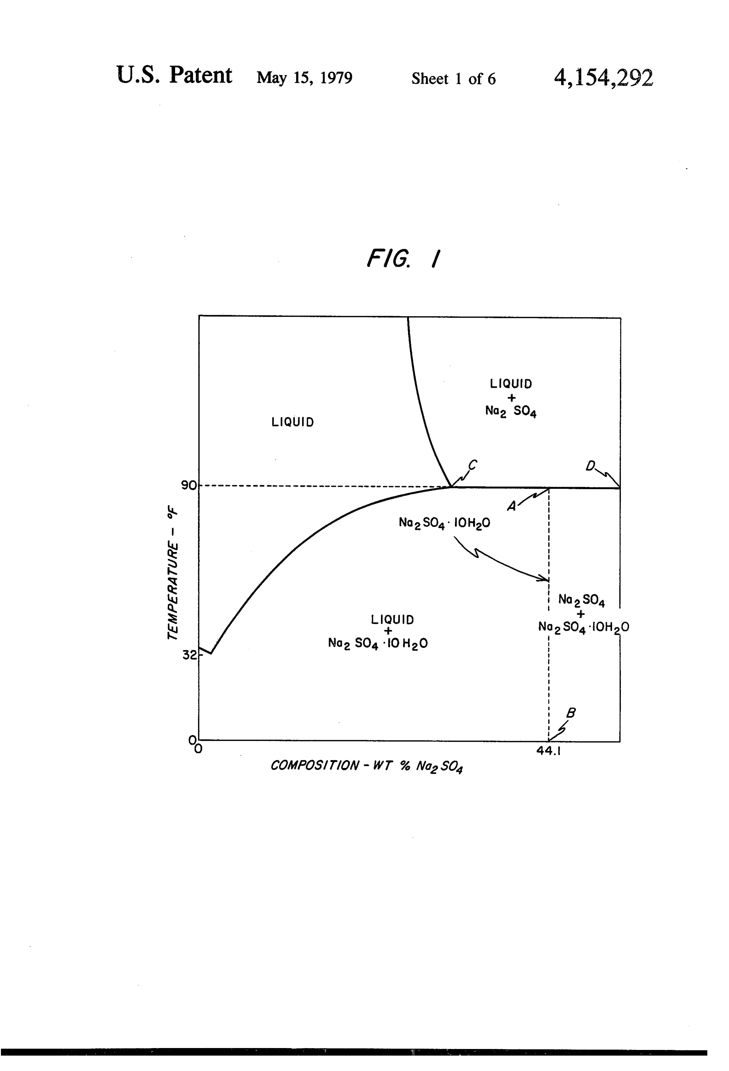
fer surface was moved relative to the crystal mass "in BREIF DESCRIPTION OF THE DRAWING order to shed the crystal mantle which forms' (page 296). Thus, a rotating coil was disposed in the crystal 60 The subject matter of the instant invention for which mass (Glauber's salt to which a small amount of borax protection is sought is presented as claims at the conclu had been added as a nucleating agent) with water being sion of the written description of the invention as set carried by the rotating coil to remove the heat. The forth herein. The description sets forth the manner and Glauber's salt was first melted by hot water passed process of making and using the invention and the ac through the coil and, subsequently, heat was withdrawn 65 companying drawing forms part of the description for by passing cool water through the rotating coil. The schematically illustrating the best mode. inevitable conclusion to be reached from the Hodgins et The view shown in FIG. 1 sets forth the pertinent al. teachings is that in a system in which thermal energy parts of the sodium sulfate-water phase diagram;
Page 9
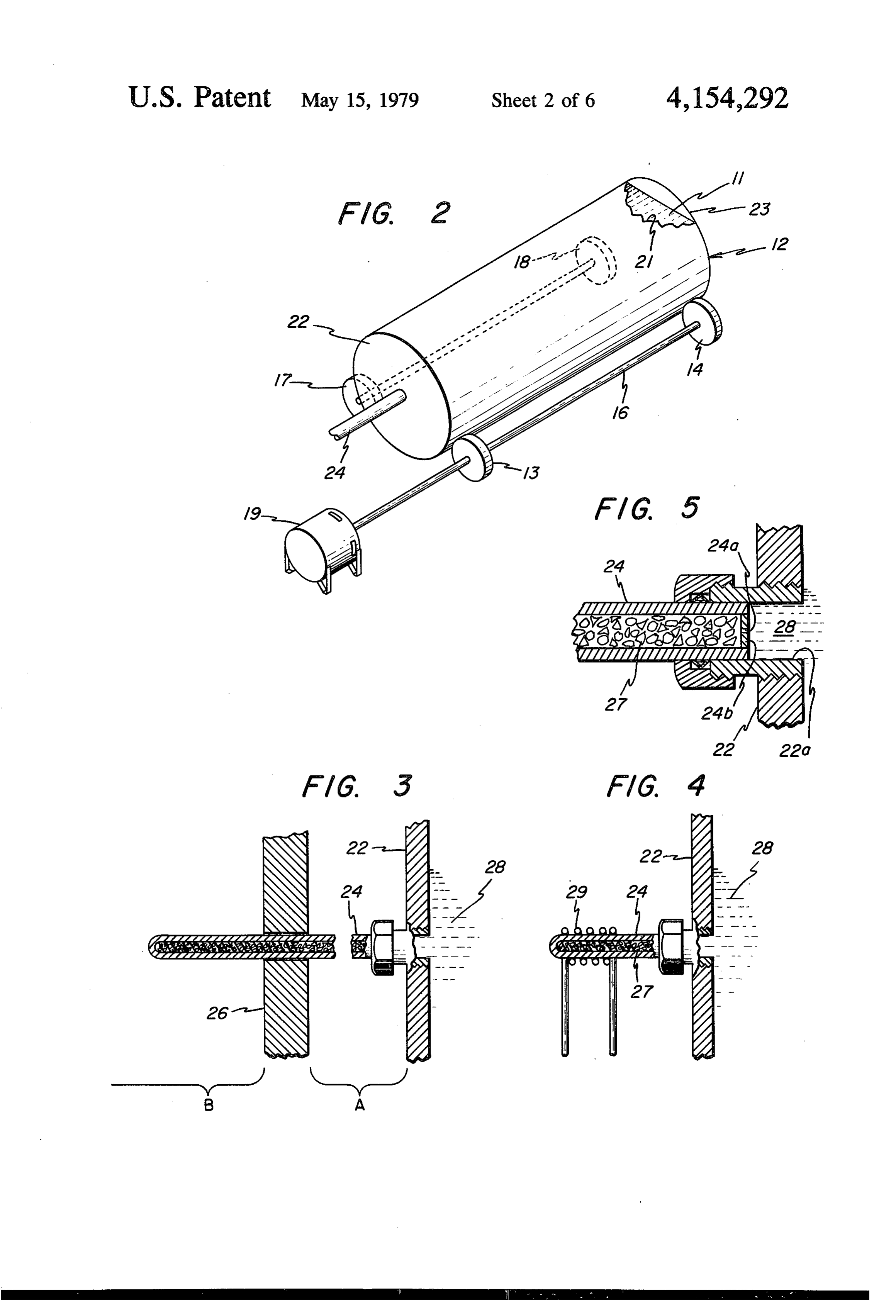
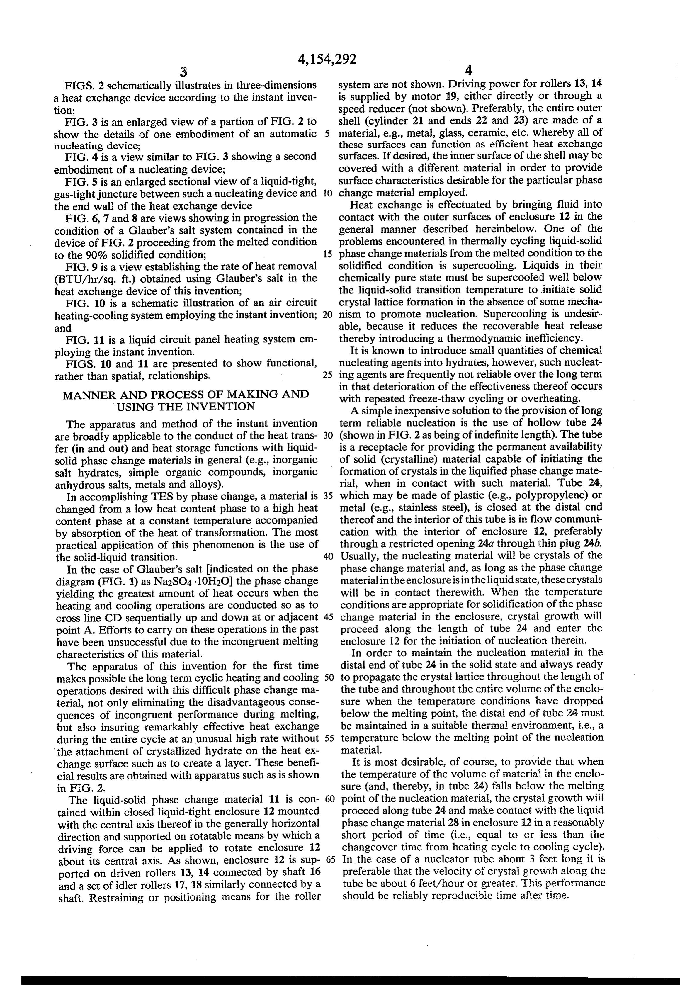
FIGS. 2 schematically illustrates in three-dimensions system are not shown. Driving power for rollers 13, 14 a heat exchange device according to the instant inven is supplied by motor 19, either directly or through a tion; speed reducer (not shown). Preferably, the entire outer FIG. 3 is an enlarged view of a partion of FIG. 2 to shell (cylinder 21 and ends 22 and 23) are made of a show the details of one embodiment of an automatic material, e.g., metal, glass, ceramic, etc. whereby all of nucleating device; these surfaces can function as efficient heat exchange FIG. 4 is a view similar to FIG. 3 showing a second surfaces. If desired, the inner surface of the shell may be embodiment of a nucleating device; covered with a different material in order to provide FIG. 5 is an enlarged sectional view of a liquid-tight, surface characteristics desirable for the particular phase gas-tight juncture between such a nucleating device and 10 change material employed.
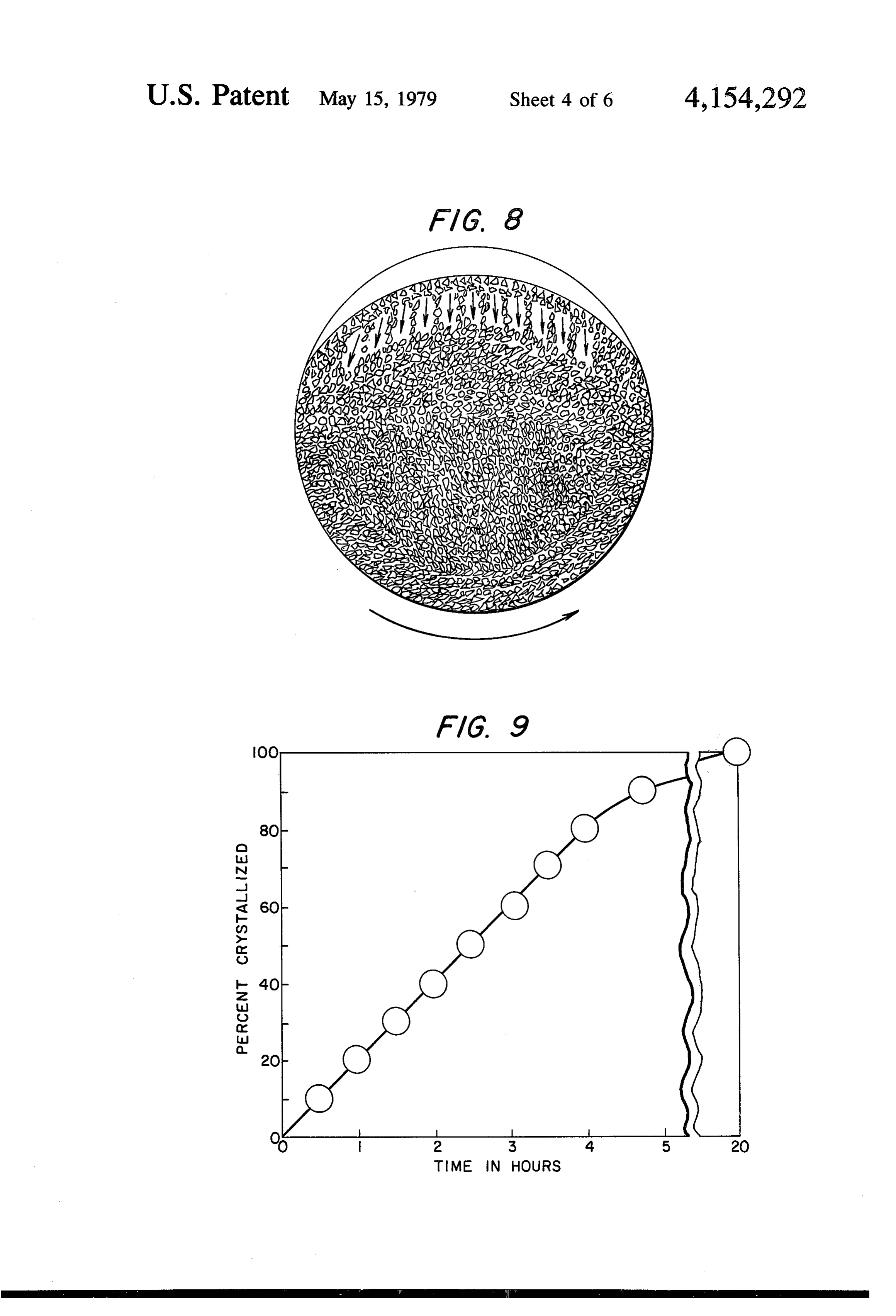
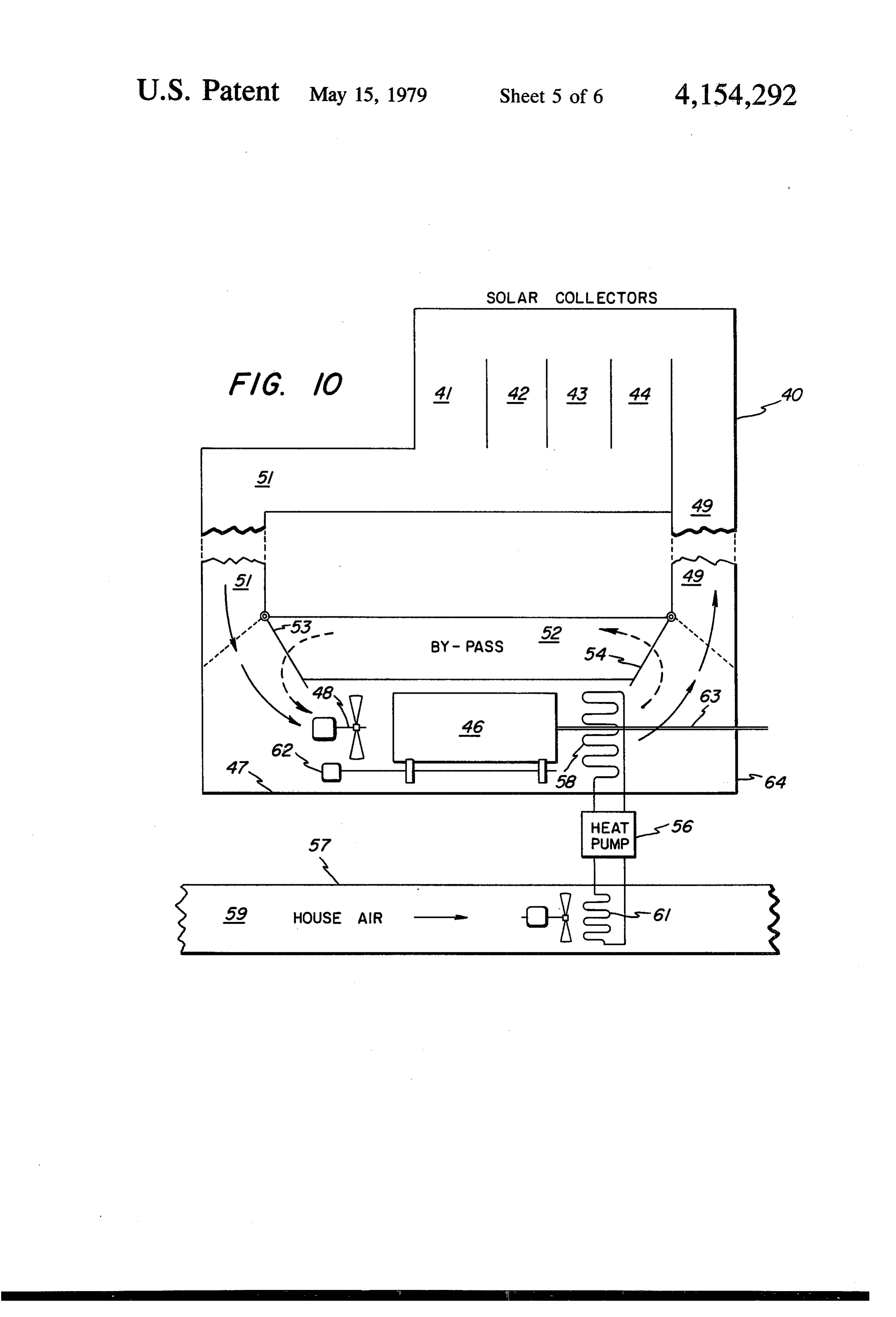
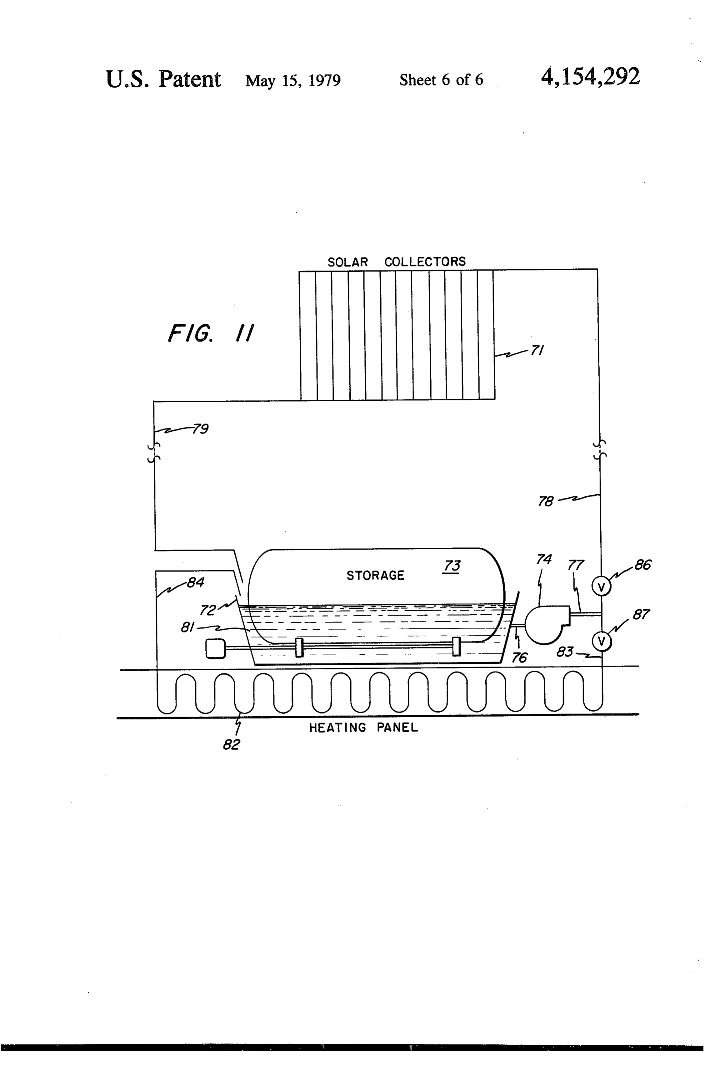
the end wall of the heat exchange device Heat exchange is effectuated by bringing fluid into FIG. 6, 7 and 8 are views showing in progression the contact with the outer surfaces of enclosure 12 in the condition of a Glauber's salt system contained in the general manner described hereinbelow. One of the device of FIG. 2 proceeding from the melted condition problems encountered in thermally cycling liquid-solid to the 90% solidified condition; 15 phase change materials from the melted condition to the FIG. 9 is a view establishing the rate of heat removal solidified condition is supercooling. Liquids in their (BTU/hr/sq. ft.) obtained using Glauber's salt in the chemically pure state must be supercooled well below heat exchange device of this invention; the liquid-solid transition temperature to initiate solid FIG. 10 is a schematic illustration of an air circuit crystal lattice formation in the absence of some mecha heating-cooling system employing the instant invention; 20 nism to promote nucleation. Supercooling is undesir and able, because it reduces the recoverable heat release FIG. 11 is a liquid circuit panel heating system em thereby introducing a thermodynamic inefficiency. ploying the instant invention. It is known to introduce small quantities of chemical FIGS. 10 and 11 are presented to show functional, nucleating agents into hydrates, however, such nucleat rather than spatial, relationships. 25 ing agents are frequently not reliable over the long term in that deterioration of the effectiveness thereof occurs
MANNER AND PROCESS OF MAKING AND with repeated freeze-thaw cycling or overheating. USING THE INVENTION A simple inexpensive solution to the provision of long The apparatus and method of the instant invention term reliable nucleation is the use of hollow tube 24 are broadly applicable to the conduct of the heat trans 30 (shown in FIG. 2 as being of indefinite length). The tube fer (in and out) and heat storage functions with liquid is a receptacle for providing the permanent availability solid phase change materials in general (e.g., inorganic of solid (crystalline) material capable of initiating the salt hydrates, simple organic compounds, inorganic formation of crystals in the liquified phase change mate anhydrous salts, metals and alloys). rial, when in contact with such material. Tube 24, In accomplishing TES by phase change, a material is 35 which may be made of plastic (e.g., polypropylene) or changed from a low heat content phase to a high heat metal (e.g., stainless steel), is closed at the distal end content phase at a constant temperature accompanied thereof and the interior of this tube is in flow communi by absorption of the heat of transformation. The most cation with the interior of enclosure 12, preferably practical application of this phenomenon is the use of through a restricted opening 24a through thin plug 24b. the solid-liquid transition. 40 Usually, the nucleating material will be crystals of the In the case of Glauber's salt indicated on the phase phase change material and, as long as the phase change diagram (FIG. 1) as Na2SO4.10H2O) the phase change material in the enclosure is in the liquid state, these crystals yielding the greatest amount of heat occurs when the will be in contact therewith. When the temperature heating and cooling operations are conducted so as to conditions are appropriate for solidification of the phase cross line CD sequentially up and down at or adjacent 45 change material in the enclosure, crystal growth will point A. Efforts to carry on these operations in the past proceed along the length of tube 24 and enter the have been unsuccessful due to the incongruent melting enclosure 12 for the initiation of nucleation therein. characteristics of this material. In order to maintain the nucleation material in the The apparatus of this invention for the first time distal end of tube 24 in the solid state and always ready makes possible the long term cyclic heating and cooling 50 to propagate the crystal lattice throughout the length of operations desired with this difficult phase change ma the tube and throughout the entire volume of the enclo terial, not only eliminating the disadvantageous conse sure when the temperature conditions have dropped quences of incongruent performance during melting, below the melting point, the distal end of tube 24 must but also insuring remarkably effective heat exchange be maintained in a suitable therinai environment, i.e., a during the entire cycle at an unusual high rate without 55 temperature below the melting point of the nucleation the attachment of crystallized hydrate on the heat ex material.
change surface such as to create a layer. These benefi It is most desirable, of course, to provide that when cial results are obtained with apparatus such as is shown the temperature of the volume of material in the enclo in F.G. 2. sure (and, thereby, in tube 24) falls below the melting The liquid-solid phase change material 11 is con 60 point of the nucleation material, the crystal growth will tained within closed liquid-tight enclosure 12 mounted proceed along tube 24 and make contact with the liquid with the central axis thereof in the generally horizontal phase change material 28 in enclosure 12 in a reasonably direction and supported on rotatable means by which a short period of time (i.e., equal to or less than the driving force can be applied to rotate enclosure 12 changeover time from heating cycle to cooling cycle). about its central axis. As shown, enclosure 12 is Sup 65 In the case of a nucleator tube about 3 feet long it is ported on driven rollers 13, 14 connected by shaft 16 preferable that the velocity of crystal growth along the and a set of idler rollers 17, 18 similarly connected by a tube be about 6 feet/hour or greater. This performance shaft. Restraining or positioning means for the roller should be reliably reproducible time after time.
Page 10
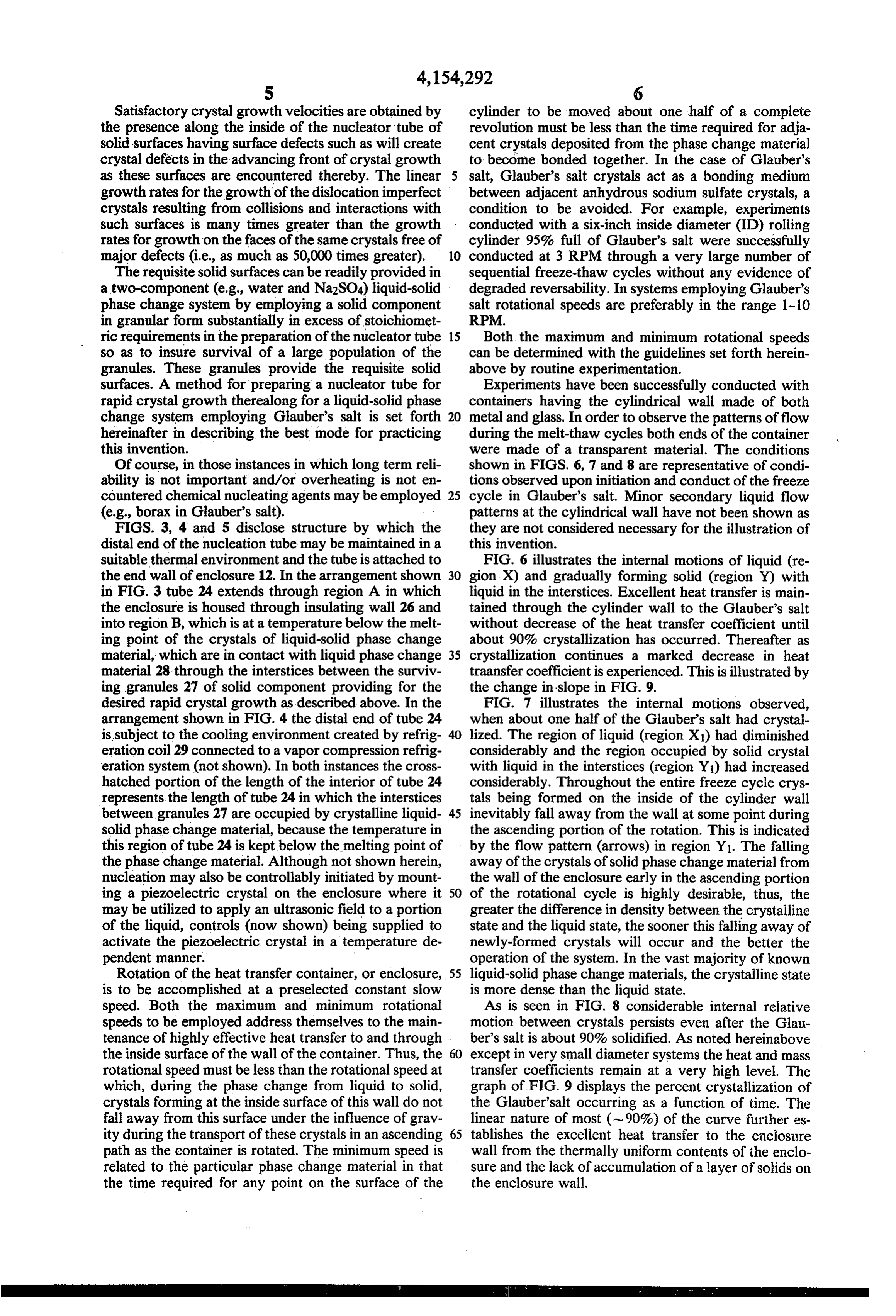
Satisfactory crystal growth velocities are obtained by cylinder to be moved about one half of a complete the presence along the inside of the nucleator tube of revolution must be less than the time required for adja solid surfaces having surface defects such as will create cent crystals deposited from the phase change material crystal defects in the advancing front of crystal growth to become bonded together. In the case of Glauber's as these surfaces are encountered thereby. The linear salt, Glauber's salt crystals act as a bonding medium growth rates for the growth of the dislocation imperfect between adjacent anhydrous sodium sulfate crystals, a crystals resulting from collisions and interactions with condition to be avoided. For example, experiments such surfaces is many times greater than the growth conducted with a six-inch inside diameter (ID) rolling rates for growth on the faces of the same crystals free of cylinder 95% full of Glauber's salt were successfully major defects (i.e., as much as 50,000 times greater). 10 conducted at 3 RPM through a very large number of The requisite solid surfaces can be readily provided in sequential freeze-thaw cycles without any evidence of a two-component (e.g., water and Na2SO4) liquid-solid degraded reversability. In systems employing Glauber's phase change system by employing a solid component salt rotational speeds are preferably in the range 1-10 in granular form substantially in excess of stoichiomet RPM.
ric requirements in the preparation of the nucleator tube 15 Both the maximum and minimum rotational speeds so as to insure survival of a large population of the can be determined with the guidelines set forth herein granules. These granules provide the requisite solid above by routine experimentation.
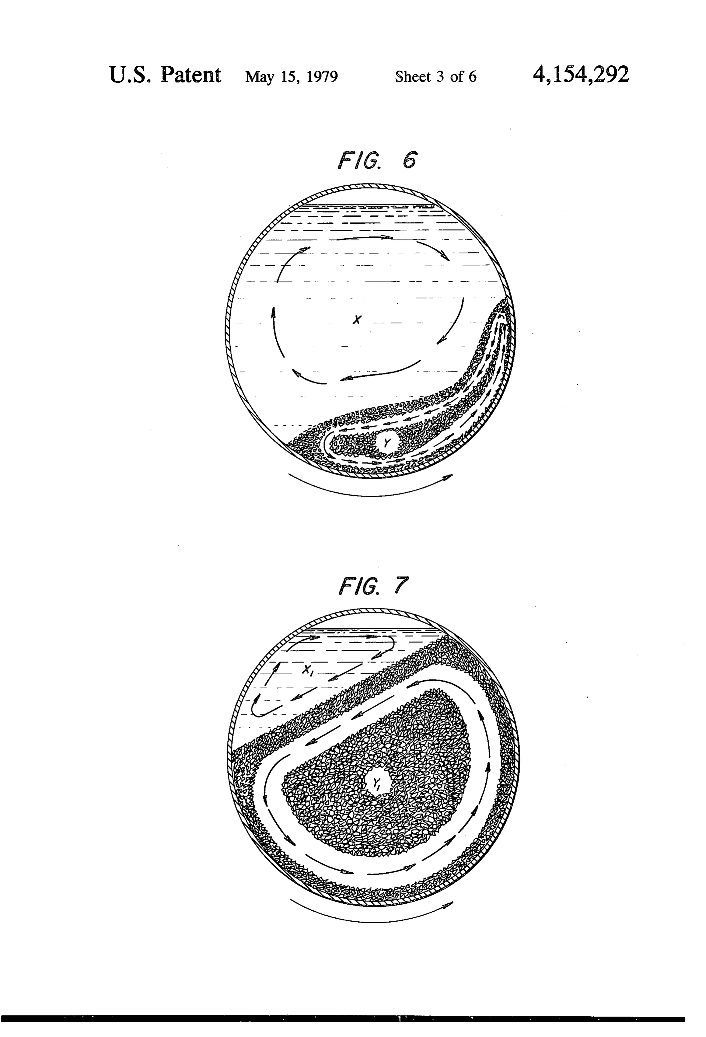
surfaces. A method for preparing a nucleator tube for Experiments have been successfully conducted with rapid crystal growth therealong for a liquid-solid phase containers having the cylindrical wall made of both change system employing Glauber's salt is set forth 20 metal and glass. In order to observe the patterns of flow hereinafter in describing the best mode for practicing during the melt-thaw cycles both ends of the container this invention. were made of a transparent material. The conditions Of course, in those instances in which long term reli shown in FIGS. 6, 7 and 8 are representative of condi ability is not important and/or overheating is not en tions observed upon initiation and conduct of the freeze countered chemical nucleating agents may be employed 25 cycle in Glauber's salt. Minor secondary liquid flow (e.g., borax in Glauber's salt). patterns at the cylindrical wall have not been shown as FIGS. 3, 4 and 5 disclose structure by which the they are not considered necessary for the illustration of distal end of the nucleation tube may be maintained in a this invention.
suitable thermal environment and the tube is attached to FIG. 6 illustrates the internal motions of liquid (re the end wall of enclosure 12. In the arrangement shown 30 gion X) and gradually forming solid (region Y) with in FIG. 3 tube 24 extends through region A in which liquid in the interstices. Excellent heat transfer is main the enclosure is housed through insulating wall 26 and tained through the cylinder wall to the Glauber's salt into region B, which is at a temperature below the melt without decrease of the heat transfer coefficient until ing point of the crystals of liquid-solid phase change about 90% crystallization has occurred. Thereafter as material, which are in contact with liquid phase change 35 crystallization continues a marked decrease in heat material 28 through the interstices between the surviv traansfer coefficient is experienced. This is illustrated by ing granules 27 of solid component providing for the the change in slope in FIG. 9.
desired rapid crystal growth as described above. In the FIG. 7 illustrates the internal motions observed, arrangement shown in FIG. 4 the distal end of tube 24 when about one half of the Glauber's salt had crystal is subject to the cooling environment created by refrig lized. The region of liquid (region X) had diminished eration coil 29 connected to a vapor compression refrig considerably and the region occupied by solid crystal eration system (not shown). In both instances the cross with liquid in the interstices (region Y) had increased hatched portion of the length of the interior of tube 24 considerably. Throughout the entire freeze cycle crys represents the length of tube 24 in which the interstices tals being formed on the inside of the cylinder wall between granules 27 are occupied by crystalline liquid 45 inevitably fall away from the wall at some point during solid phase change material, because the temperature in the ascending portion of the rotation. This is indicated this region of tube 24 is kept below the melting point of by the flow pattern (arrows) in region Y1. The falling the phase change material. Although not shown herein, away of the crystals of solid phase change material from nucleation may also be controllably initiated by mount the wall of the enclosure early in the ascending portion ing a piezoelectric crystal on the enclosure where it 50 of the rotational cycle is highly desirable, thus, the may be utilized to apply an ultrasonic field to a portion greater the difference in density between the crystalline of the liquid, controls (now shown) being supplied to state and the liquid state, the sooner this falling away of activate the piezoelectric crystal in a temperature de newly-formed crystals will occur and the better the pendent manner. operation of the system. In the vast majority of known Rotation of the heat transfer container, or enclosure, 55 liquid-solid phase change materials, the crystalline state is to be accomplished at a preselected constant slow is more dense than the liquid state.
speed. Both the maximum and minimum rotational As is seen in FIG. 8 considerable internal relative speeds to be employed address themselves to the main motion between crystals persists even after the Glau tenance of highly effective heat transfer to and through . ber's salt is about 90% solidified. As noted hereinabove the inside surface of the wall of the container. Thus, the 60 except in very small diameter systems the heat and mass rotational speed must be less than the rotational speed at transfer coefficients remain at a very high level. The which, during the phase change from liquid to solid, graph of FIG. 9 displays the percent crystallization of crystals forming at the inside surface of this wall do not the Glauber'salt occurring as a function of time. The fall away from this surface under the influence of grav linear nature of most (~90%) of the curve further es ity during the transport of these crystals in an ascending 65 tablishes the excellent heat transfer to the enclosure path as the container is rotated. The minimum speed is wall from the thermally uniform contents of the enclo related to the particular phase change material in that sure and the lack of accumulation of a layer of solids on the time required for any point on the surface of the the enclosure wall.
Page 11
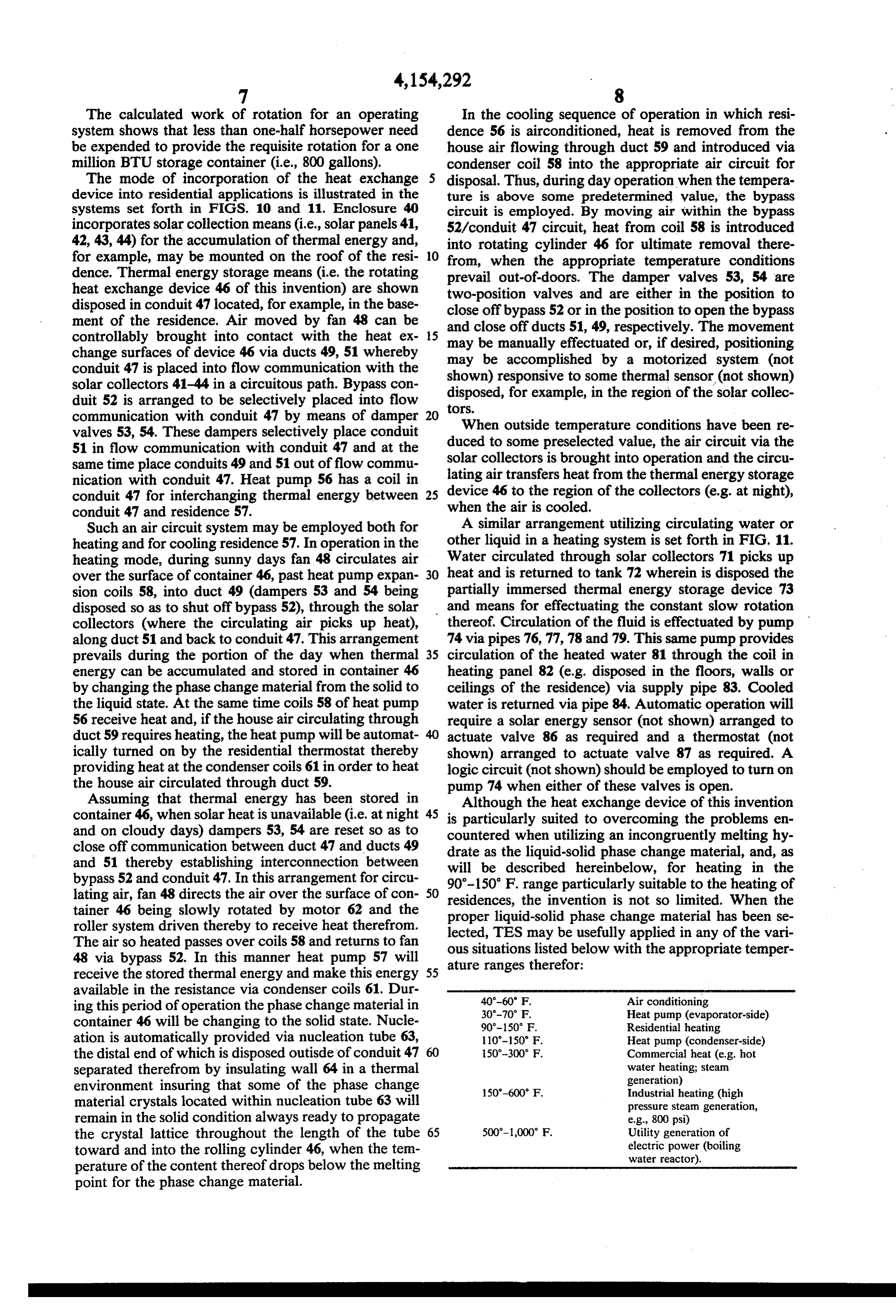
The calculated work of rotation for an operating In the cooling sequence of operation in which resi system shows that less than one-half horsepower need dence 56 is airconditioned, heat is removed from the be expended to provide the requisite rotation for a one house air flowing through duct 59 and introduced via million BTU storage container (i.e., 800 gallons). condenser coil 58 into the appropriate air circuit for The mode of incorporation of the heat exchange disposal. Thus, during day operation when the tempera device into residential applications is illustrated in the ture is above some predetermined value, the bypass systems set forth in FIGS. 10 and 11. Enclosure 40 circuit is employed. By moving air within the bypass incorporates solar collection means (i.e., solar panels 41, 52/conduit 47 circuit, heat from coil 58 is introduced 42, 43,44) for the accumulation of thermal energy and, into rotating cylinder 46 for ultimate removal there for example, may be mounted on the roof of the resi 10 from, when the appropriate temperature conditions dence. Thermal energy storage means (i.e. the rotating prevail out-of-doors. The damper valves 53, 54 are heat exchange device 46 of this invention) are shown two-position valves and are either in the position to disposed in conduit 47 located, for example, in the base close off bypass 52 or in the position to open the bypass ment of the residence. Air moved by fan 48 can be controllably brought into contact with the heat ex 15 and close off ducts 51, 49, respectively. The movement change surfaces of device 46 via ducts 49, 51 whereby may bebe manually may effectuated or, if desired, positioning accomplished by a motorized system (not conduit 47 is placed into flow communication with the shown) responsive to some thermal sensor (not shown) solar collectors 41-44 in a circuitous path. Bypass con disposed, for example, in the region of the solar collec duit 52 is arranged to be selectively placed into flow tors.
communication with conduit 47 by means of damper 20 When outside temperature conditions have been re valves 53, 54. These dampers selectively place conduit duced to some preselected value, the air circuit via the 51 in flow communication with conduit 47 and at the solar collectors same time place conduits 49 and 51 out of flow commu lating air transfers is brought into operation and the circu nication with conduit 47. Heat pump 56 has a coil in heat from the thermal energy storage conduit 47 for interchanging thermal energy between when the air is cooled. of the collectors (e.g. at night), 25 device 46 to the region conduit 47 and residence 57.
Such an air circuit system may be employed both for A similar arrangement utilizing circulating water or heating and for cooling residence 57. In operation in the other liquid in a heating system is set forth in FIG. 11. heating mode, during sunny days fan 48 circulates air Water circulated through solar collectors 71 picks up over the surface of container 46, past heat pump expan 30 heat and is returned to tank 72 wherein is disposed the sion coils 58, into duct 49 (dampers 53 and 54 being partially immersed thermal energy storage device 73 disposed so as to shut off bypass 52), through the solar and means for effectuating the constant slow rotation collectors (where the circulating air picks up heat), thereof. Circulation of the fluid is effectuated by pump along duct 51 and back to conduit 47. This arrangement 74 via pipes 76, 77,78 and 79. This same pump provides prevails during the portion of the day when thermal 35 circulation of the heated water 81 through the coil in energy can be accumulated and stored in container 46 heating panel 82 (e.g. disposed in the floors, walls or by changing the phase change material from the solid to ceilings of the residence) via supply pipe 83. Cooled the liquid state. At the same time coils 58 of heat pump water is returned via pipe 84. Automatic operation will 56 receive heat and, if the house air circulating through require a solar energy sensor (not shown) arranged to duct 59 requires heating, the heat pump will be automat actuate valve 86 as required and a thermostat (not ically turned on by the residential thermostat thereby shown) arranged to actuate valve 87 as required. A providing heat at the condenser coils 61 in order to heat logic circuit (not shown) should be employed to turn on the house air circulated through duct 59. pump 74 when either of these valves is open. Assuming that thermal energy has been stored in Although the heat exchange device of this invention container 46, when solar heat is unavailable (i.e. at night 45 is particularly suited to overcoming the problems en and on cloudy days) dampers 53, 54 are reset so as to countered when utilizing an incongruently melting hy close off communication between duct 47 and ducts 49 drate as the liquid-solid phase change material, and, as and 51 thereby establishing interconnection between will be described hereinbelow, for heating in the bypass 52 and conduit 47. In this arrangement for circu 90-150 F. range particularly suitable to the heating of lating air, fan 48 directs the air over the surface of con
tainer 46 being slowly rotated by motor 62 and the residences, the invention is not so limited. When the proper liquid-solid phase change material has been se roller system driven thereby to receive heat therefrom. lected, TES may be usefully applied in any of the vari The air so heated passes over coils 58 and returns to fan ous 48 via bypass 52. In this manner heat pump 57 will aturesituations ranges listed below with the appropriate temper therefor:
receive the stored thermal energy and make this energy 55 available in the resistance via condenser coils 61. Dur ing this period of operation the phase change material in 40-60 F. Air conditioning
container 46 will be changing to the solid state. Nucle 90-150 F. Residential heating ation is automatically provided via nucleation tube 63, 110-150 F. Heat pump (condenser-side) the distal end of which is disposed outisde of conduit 47 150-300 F. Commercial heat (e.g. hot separated therefrom by insulating wall 64 in a thermal water heating; steam generation) environment insuring that some of the phase change 50-600 F. Industrial heating (high material crystals located within nucleation tube 63 will pressure steam generation, remain in the solid condition always ready to propagate e.g., 800 psi) the crystal lattice throughout the length of the tube 65 500-1,000 F. Utility generation of electric power (boiling toward and into the rolling cylinder 46, when the tem water reactor). perature of the content thereof drops below the melting point for the phase change material.
Page 12
BEST MODE CONTEMPLATED means for rotating said enclosure around said axis and means affixed to said enclosure for predetermining
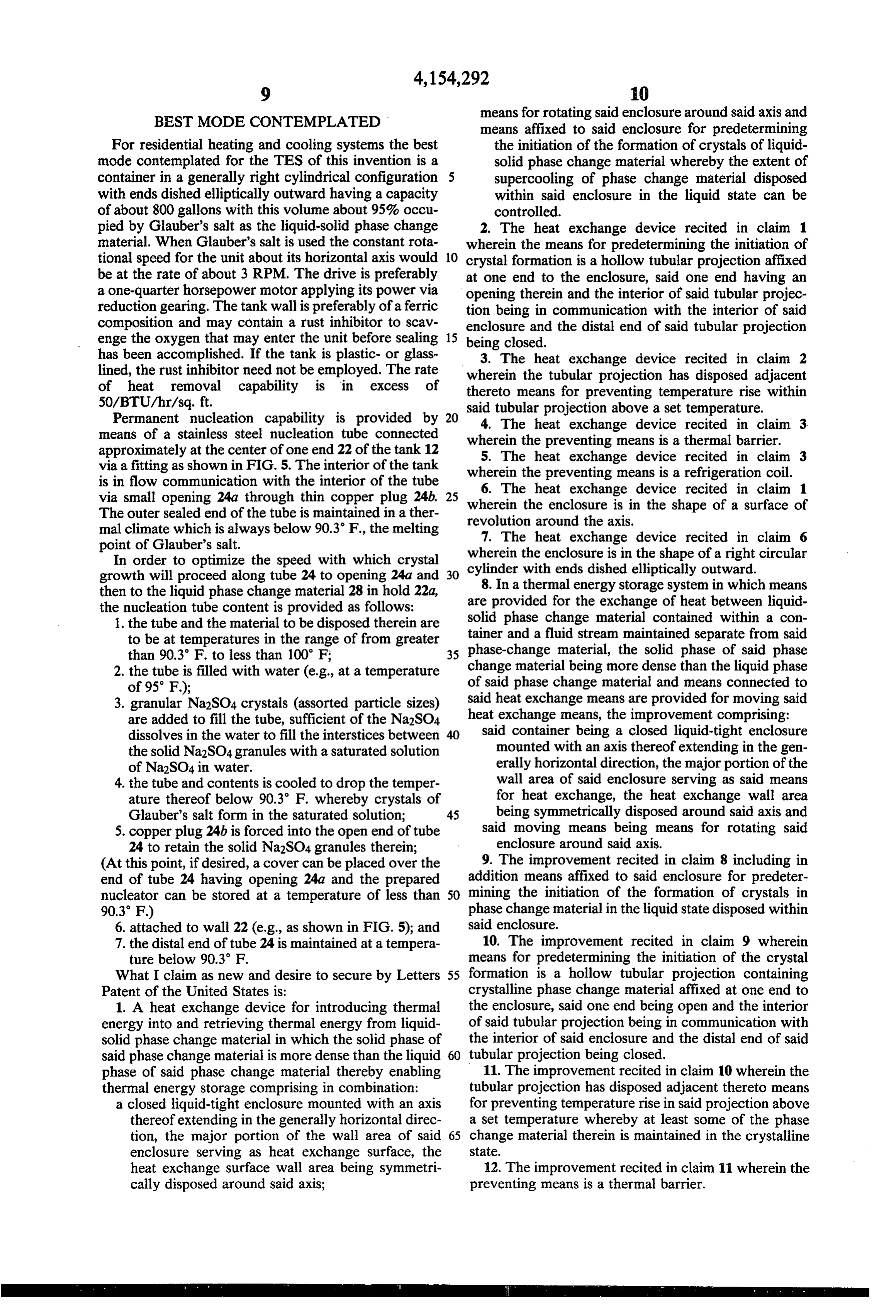
For residential heating and cooling systems the best the initiation of the formation of crystals of liquid mode contemplated for the TES of this invention is a solid phase change material whereby the extent of container in a generally right cylindrical configuration supercooling of phase change material disposed with ends dished elliptically outward having a capacity within said enclosure in the liquid state can be of about 800 gallons with this volume about 95% occu controlled.
pied by Glauber's salt as the liquid-solid phase change 2. The heat exchange device recited in claim 1 material. When Glauber's salt is used the constant rota wherein the means for predetermining the initiation of tional speed for the unit about its horizontal axis would O crystal formation is a hollow tubular projection affixed be at the rate of about 3 RPM. The drive is preferably at one end to the enclosure, said one end having an a one-quarter horsepower motor applying its power via opening therein and the interior of said tubular projec reduction gearing. The tank wall is preferably of a ferric tion being in communication with the interior of said composition and may contain a rust inhibitor to scav enclosure and the distal end of said tubular projection enge the oxygen that may enter the unit before sealing 15 being closed.
has been accomplished. If the tank is plastic- or glass 3. The heat exchange device recited in claim 2 lined, the rust inhibitor need not be employed. The rate wherein the tubular projection has disposed adjacent of heat removal capability is in excess of thereto means for preventing temperature rise within
Permanent nucleation capability is provided by 20 said4. tubular
The projection above a set temperature.
heat exchange device recited in claim 3 means of a stainless steel nucleation tube connected wherein the preventing means is a thermal barrier. approximately at the center of one end 22 of the tank 12 5. The heat exchange device recited in claim 3 via a fitting as shown in FIG. 5. The interior of the tank wherein the preventing means is a refrigeration coil. is in flow communication with the interior of the tube 6. The heat exchange device via small opening 24a through thin copper plug 24b. wherein the enclosure is in the shape
The outer sealed end of the tube is maintained in a ther of a surface of mal climate which is always below 90.3 F., the melting revolution
around the axis.
heat exchange device recited in claim 6 point of Glauber's salt. wherein the enclosure is in the shape of a right circular In order to optimize the speed with which crystal growth will proceed along tube 24 to opening 24a and 30 cylinder with ends dished elliptically outward. then to the liquid phase change material 28 in hold 22a, are8.provided
In a thermal energy storage system in which means for the exchange of heat between liquid the nucleation tube content is provided as follows:
1. the tube and the material to be disposed therein are solid phase change material contained within a con to be at temperatures in the range of from greater tainer and a fluid stream maintained separate from said than 90.3 F. to less than 100 F; 35 phase-change material, the solid phase of said phase 2. the tube is filled with water (e.g., at a temperature change material being more dense than the liquid phase of 95°F); of said phase change material and means connected to 3. granular Na2SO4 crystals (assorted particle sizes) said heat exchange means are provided for moving said are added to fill the tube, sufficient of the Na2SO4. heat exchange means, the improvement comprising: dissolves in the water to fill the interstices between said container being a closed liquid-tight enclosure the solid Na2SO4 granules with a saturated solution mounted with an axis thereof extending in the gen of Na2SO4 in water. erally horizontal direction, the major portion of the 4. the tube and contents is cooled to drop the temper wall area of said enclosure serving as said means ature thereof below 90.3 F. whereby crystals of for heat exchange, the heat exchange wall area Glauber's salt form in the saturated solution; 45 being symmetrically disposed around said axis and 5. copper plug 24b is forced into the open end of tube said moving means being means for rotating said 24 to retain the solid Na2SO4 granules therein; enclosure around said axis.
(At this point, if desired, a cover can be placed over the 9. The improvement recited in claim 8 including in end of tube 24 having opening 24a and the prepared addition means affixed to said enclosure for predeter nucleator can be stored at a temperature of less than 50 mining the initiation of the formation of crystals in 90.3°F) phase change material in the liquid state disposed within 6. attached to wall 22 (e.g., as shown in FIG. 5); and said enclosure.
7. the distal end of tube 24 is maintained at a tempera 10. The improvement recited in claim 9 wherein ture below 90.3 F. means for predetermining the initiation of the crystal What I claim as new and desire to secure by Letters 55 formation is a hollow tubular projection containing Patent of the United States is: crystalline phase change material affixed at one end to 1. A heat exchange device for introducing thermal the enclosure, said one end being open and the interior energy into and retrieving thermal energy from liquid of said tubular projection being in communication with solid phase change material in which the solid phase of the interior of said enclosure and the distal end of said said phase change material is more dense than the liquid 60 tubular projection being closed. phase of said phase change material thereby enabling 11. The improvement recited in claim 10 wherein the thermal energy storage comprising in combination: tubular projection has disposed adjacent thereto means a closed liquid-tight enclosure mounted with an axis for preventing temperature rise in said projection above thereof extending in the generally horizontal direc a set temperature whereby at least some of the phase tion, the major portion of the wall area of said 65 change material therein is maintained in the crystalline enclosure serving as heat exchange surface, the State.
heat exchange surface wall area being symmetri 12. The improvement recited in claim 11 wherein the cally disposed around said axis; preventing means is a thermal barrier.
Page 13
13. The improvement recited in claim 11 wherein the face under the influence of gravity during carriage preventing means is a refrigeration coil. thereof in an ascending path. 14. The improvement recited in claim 8 wherein the 17. The improved method recited in claim 16 wherein means provided for the exchange of heat includes a duct heat is removed from the rotating container at the rate containing the enclosure and a fan unit for moving air 5 of about 50 BTU/hr/sq. ft.
over the outer surface of the enclosure and the thermal 18. The improved method recited in claim 16 wherein energy storage system also includes means for selec the speed of rotation is in the range of from 1 to 10 tively placing said duct into flow communication at revolutions per minute.
each end thereof with heating means for said air and 19. The improved method recited in claim 16 wherein placing said duct into flow communication at each end 10 the liquid-solid phase change material is an incongru thereof with a by-pass duct. ently melting hydrate.
15. The improvement recited in claim 8 wherein the 20. The improved method recited in claim 19 wherein means provided for the exchange of heat includes a the hydrate is Na2SO4.10H2O.
pump and first conduits for circulating liquid in a circuit 21. The improved method recited in claim 16 wherein by which heated liquid is brought into contact with the 15 nucleation of crystals of the solid phase is automatically outer surface of the enclosure and is returned to a provided during the phase change from liquid to solid. source of heat therefor and second conduits by which 22. The improved method recited in claim 21 wherein liquid heated by contact with the outer surface of said the solid form of the liquid-solid phase change material enclosure is circulated to and from a heat demand vol is Na2SO4.10H2O and the speed of the automatic nucle , ation thereof is increased by providing solid Na2SO4 16. In the method of storing thermal energy in and granules in at least part of the path of the developing retrieveing thermal energy from a liquid-solid phase crystals of Na2SO4.10H2O.
change material, the solid phase of said phase change 23. The improved method recited in claim 22 wherein material being more dense than the liquid phase of said the path of the developing crystals is in an overall pre phase change matérial, wherein said phase change mate- 25 dominately linear direction.
rial is maintained in a container and fluid is circulated 24. The improved method recited in claim 20 wherein over the outer surface of said container to effectuate the the nucleation is accomplished with solid crystalline desired heat exchange, the improvement comprising the material of the same composition as the phase change steps of: material.
rotating said container at a preselected constant rota- 30 25. The improved method recited in claim 21 wherein tional speed about a generally horizontal axis, said the solid crystalline material is kept at a temperature rotational speed being less than the rotational speed below the transition temperature.
at which, during the phase change from liquid to 26. The improved method recited in claim 16 wherein solid, solid formed at the inside surface of the wall the container is continuously
rotated.
of said container does not fall away from said sur- 35
Provenance
- Collection
- Cited prior art
- Original PDF
- patentimages.storage.googleapis.com →
- Filed
- 1978-01-11
- Pages
- 13
- Method
- pdftotext (the PDF's own text layer) + pdftoppm 300dpi page scans
- Source
- Google Patents bibliographic record
- Granted
- 1979-05-15
- Inventors
- Carlyle S. Herrick; General Electric Co
- Transcribed from
- patentimages.storage.googleapis.com →