patent · US4605837
Electric air preheater for an internal combustion engine
12 August 1986
Page 1 — bibliographic record
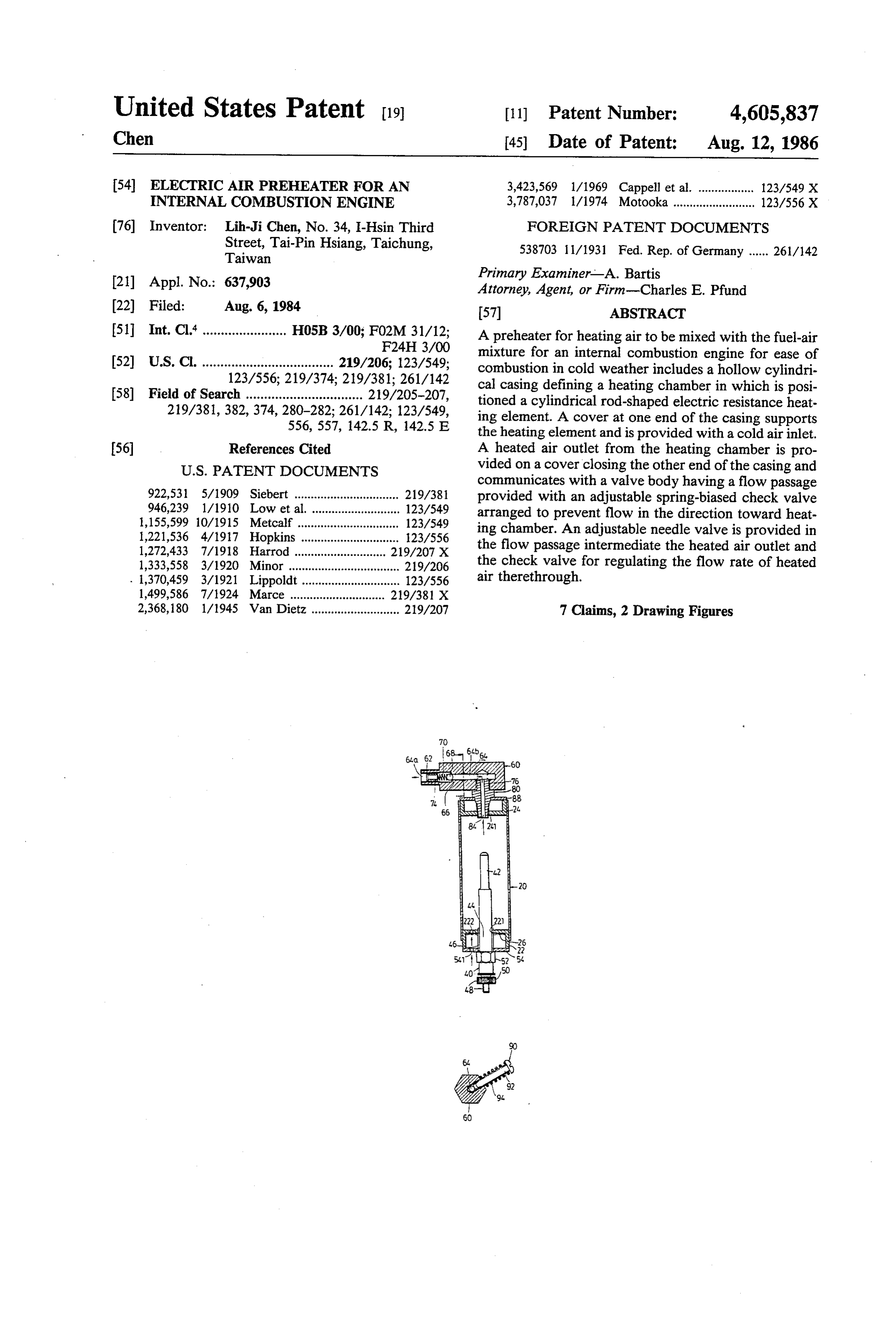
United States Patent (19) 11 Patent Number: 4,605,837 Chen (45) Date of Patent: Aug. 12, 1986 54) ELECTRIC AIR PREHEATER FOR AN 3,423,569 1/1969 Cappell et al. ................. 123/549 X INTERNAL COMBUSTION ENGINE 3,787,037 1/1974 Motooka ......................... 123/556X (76) Inventor: Lih-Ji Chen, No. 34, I-Hsin Third FOREIGN PATENT DOCUMENTS Street, Tai-Pin Hsiang, Taichung, 538703 11/1931 Fed. Rep. of Germany ...... 26/142 Taiwan (21) Appl. No.: 637,903 Primary Examiner-A. Bartis Attorney, Agent, or Firm-Charles E. Pfund 22 Filed: Aug. 6, 1984 57 ABSTRACT 51 Int. Cl. ....................... H05B 3/00; F02M 31/12; A preheater for heating air to be mixed with the fuel-air F24H 3/00 mixture for an internal combustion engine for ease of 52) U.S. C. .................................... 219/206; 123/549; combustion in cold weather includes a hollow cylindri 123/556; 219/374; 219/381; 261/142 cal casing defining a heating chamber in which is posi 58) Field of Search ................................ 219/205-207, tioned a cylindrical rod-shaped electric resistance heat 219/381,382, 374, 280-282; 261/142; 123/549, ing element. A cover at one end of the casing supports 556, 557, 142.5 R, 142.5 E the heating element and is provided with a cold air inlet. (56) References Cited A heated air outlet from the heating chamber is pro
communicates with a valve body having a flow passage 922,531 5/1909 Siebert ................................ 219/381 provided with an adjustable spring-biased check valve 946,239 1/1910 Low et al. ........................... 123/549 arranged to prevent flow in the direction toward heat 1,155,599 10/1915 Metcalf ............................... 123/549 ing chamber. An adjustable needle valve is provided in 1,221,536 4/1917 Hopkins .............................. 123/556 the flow passage intermediate the heated air outlet and 1,272,433 7/1918 Harrod ... . 219/207 X 1,333,558 3/1920 Minor .................................. 219/206 the check valve for regulating the flow rate of heated . 1,370,459 3/1921 Lippoldt .............................. 123/556 air therethrough.
1,499,586 7/1924 Marce ......... 219/381 X 2,368, 180 1/1945 Van Dietz ........................... 219/207 7 Claims, 2 Drawing Figures
Page 2
Drawing sheet — no readable text.
Page 3
cover 22 of which one side is further provided with an
ELECTRIC AIR PREHEATER FOR AN INTERNAL air filter 26.
COMBUSTON ENGINE The heating unit 40 includes an upper portion which
BACKGROUND OF THE INVENTION
is an excellent resistance element 42, such as made of a 5 nickel chromiun alloy. The intermediate portion 44 is
This invention relates to a heating device, particu provided with male thread formation 46, and the lower larly to a preheater for heating air which in turn is to be end portion is a screw rod 48. A knob 50 is further mixed with the fuel-air mixture for the ease of combus provided in a rotatable position with respect to the tion in a cold weather. screw rod 48. By means of the knob 50 and the screw It is known in the art to preheat the air before enter 10 rod 48 an electric wire (not shown) from a power ing into the engine so that a warm fuel-air mixture can source can be attached to the heater 40. There is further be rendered for ease of combustion. In one form of the provided a hexagonal nut 52 between the intermediate preheater, the air is preheated by the heat of the ex portion 44 and the screw rod 48. The thread formation haust. In another form of the preheter, the air is heated 46 of the intermediate portion 44 is threadedly passed by the heat of the engine body. However, it is found 15 through the threaded hole 221 and the heating unit 40 is that both are deficient since they can only heat the air locked against movement by using an annular plate 54 after the engine operates. If the engine is required to and turning the nut 52 against the plate 54. The annular start in a very cold weather, the above preheaters are of plate 54 is also provided with an air inlet hole 541.
20 The valve body 60 can be of any shape, such as,
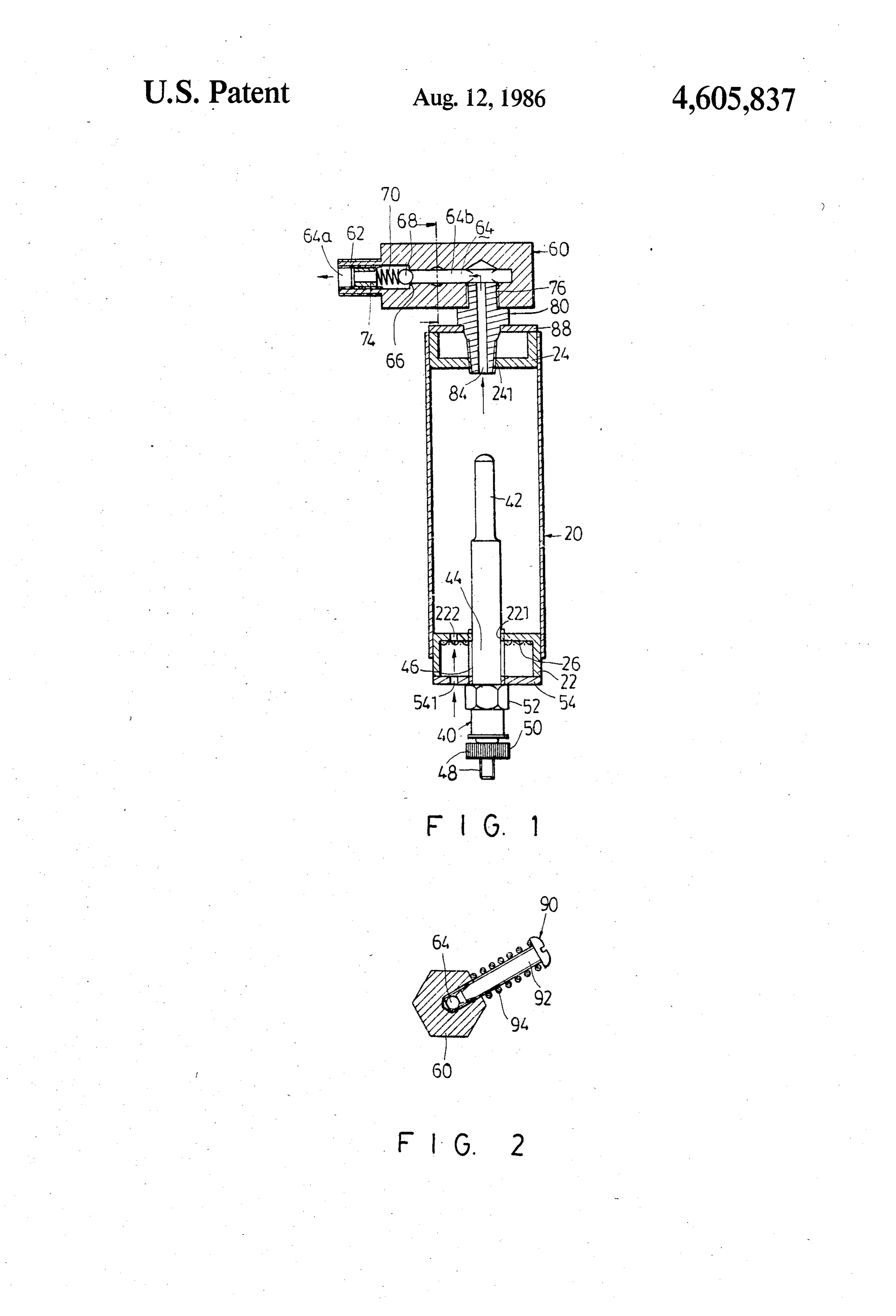
SUMMARY OF THE INVENTION circular, rectangular or polygonal shape, in its crosssec An object of the invention is to provide a preheater to tion and in this embodiment it is preferably a hexagonal shape in its cross section. The body 60 has a small diam heat the air which in turn heats the fuel-air mixture by eter portion 62 having male threads 62a provided being mixed together in the engine, thereby rendering thereon. There is further provided a blind channel 64 the fuel to volatilize completely and the mixture to burn 25 having a larger cross section portion 64a and a shoulder more easily and more completely. 66 and a smaller cross section portion 64b. A ball 68 is Another object of the invention is to provide a pre heater to heat the air before the engine is started, located in the larger cross section portion 64a in which is further provided a spring 70 biassing the ball 68 thereby eliminating the above described disadantages. against the shoulder 66, thereby blocking the smaller The foregoing and other objects can be achieved in 30 cross section portion 64b. The biassing force of the accordance with the present invention through the provision of a preheater which comprises a cylindrical spring 70 can be adjusted by means of a hollow plug casing having its two ends provided with two covers member 74 which is threadedly inserted in the larger respectively, an electric heating unit mounted to one of cross section portion 64a, said cover and extending into the casing, and a valve 35 There is further provided a threaded hole 76 which is body mounted the other said cover for regulating the communicated with the smaller cross section 64b. In the flow of the heated air to the engine. threaded hole 76 is inserted a portion of an adaptor 80 In one aspect of the invention, the preheater may which has a passage 84 in communication with the further comprises a needle valve for regulating the air smaller cross section 64b. The lower end of the adaptor flow in the valve body. 40 is screwed into the cover 24 of the casing 20 and is In another aspect of the invention, the valve body locked against movement by using an annular plate 88. may include a valve ball which can allow the air to flow Referring to FIG. 2, there is further provided a nee only in one direction. dle valve 90 which includes a screw 92 and a spring 94 In further aspect of the invention, the valve body may sleeved onto the screw 92. The screw 92 has a conical include a passage having a larger cross section portion, 45 portion and is threaded into a radial opening 63 entering a smaller cross section portion and a shoulder formation into the hexagonal body 60, along the line perpendicu between said larger and smaller cross section portions, lar to the longitudinal axis of the body 60, until it and a spring loaded valve ball normally biassed to abut reaches the blind channel channel 64. The needle valve against said shoulder. 90 is provided for regulating the flow of the air through The presently exemplary preferred embodiment will 50 the channel 64. It is specifically designed to match with be described in detail with reference to the accompany the desired engine.
ing drawings. In operation, the casing 20 of the device is grounded BRIEF DESCRIPTION OF THE DRAWING by being connected to and communicated with the air-fuel mixture inlet of the engine between the engine
FIG. 1 is a sectioned view of a preheater in accor 55 and the carburetor. The screw rod 48 is electrically dance with the present invention; and connected to the positive terminal of the battery FIG. 2 is a sectioned view of the valve body taken through a switch (not shown). When the engine is to be along the line 2-2 of FIG. 1. operated during the cold weather, an electric power is DETAILED DESCRIPTION OF THE supplied to the heating unit 40. The surrounding cold 60 air which passes through the air inlet 541 and 222 is
PREFERRED EMBODIMENT heated in the cylindrical casing 20. When the engine is Referring to FIG. 1, there is shown a preheater started, the suction stroke of the engine suctions the which includes a hollow cylindrical casing 20, a heating fuel-air mixture from the carburetor and at the same unit 40 and a valve body 60. The hollow cylindrical time causes the ball 68 to move apart from the shoulder casing is provided with two covers 22 and 24 which are 65 so that the hot air from the casing 20 is drawn into the press fitted to two ends of the casing 20. The covers 22 air-fuel mixture inlet and mixed with the air-fuel mix and 24 are respectively provided with threaded holes ture from the carburetor. Due to the presence of the 221 and 241. An air inlet hole 222 is provided at the preheater of the invention, the air-fuel mixture is heated
Page 4
by the preheated air, thereby rendering the combustion vent flow in a direction from the open end toward the more easy and also increasing the efficiency of the com closed end.
bustion. In addition, the provision of a preheater also 2. A preheater according to claim 1 comprising an reduces the fuel consumption. After the combustion is adjustable needle valve located in the flow passage of started, the air need not be heated by the preheater 40 the valve body intermediate the open and closed ends and therefore the preheater 40 can be cut off from the ends thereof and downstream of the connection be battery. tween the flow passage of the valve body and the flow It can be appreciated that, when the engine fires, the passage of the coupling element for regulating the flow pressure generated will cause the ball 68 to abut against of air through the flow passage of the valve body. the shoulder 66, thereby preventing the reverse flow of 10 3. A preheater according to claim 2 wherein the the combustion gases into the casing 20.
With the invention thus explained, it is apparent that ing, the inner end ofa which valve body contains radially-disposed threaded open is in communication with obvious modifications and variations can be made with out departing from the scope of the invention. It is into the flow passage therein, the needle valve is threaded therefore intended that the invention be limited as indi 15 said radially-disposed opening with its inner end cated in the appended claims. extending into said flow passage and its outer end ex I claim: tending radially outward from the valve body and is 1. A preheater adapted to be connected to an internal provided with a head and a coil spring is disposed about combustion engine comprising a hollow cylinder, a the needle valve with its opposite ends engaged, respec cover element at each end of the hollow cylinder, said tively, with the valve body and the head. hollow cylinder and cover elements collectively defin 4. A preheater according to claim 1 wherein said flow ing an elongate closed heating chamber, an elongate passage in the valve body is defined by adjoining coax electric heating element in the form of a cylindrical rod ial passages of different diameter providing at their supported by the cover element at one end of the hol junction an annular valve seat facing the open end of the low cylinder in coaxial relation with the longitudinal 25 flow passage and the spring-biased valve element is axis of the hollow cylinder such as to define with the spring-biased against said annular valve seat. wall of said cylinder an annular space surrounding the 5. A preheater according to claim 1 wherein the heat heating element, said cover element at said one end ing element is comprised of nickel chromium alloy. containing an opening defining an air inlet passage into 6. A preheater according to claim 5 wherein a said annular space within said heating chamber, a valve 30 threaded sleeve is threaded into the open end of the body defining a flow passage closed at one end and flow passage in the valve body and the spring of said open at the other, a coupling element connecting the spring-biased check valve element is disposed in the valve body to the cover element at the other end of the flow passage between the inner end of the sleeve and hollow cylinder and embodying a flow passage in com the valve element for biasing the latter against the seat munication at one end with the annular space within 35 and said sleeve is adjustable to vary the resistance of the said heating chamber and at the other end with the flow valve element to displacement.
passage in the valve body intermediate the ends of the 7. A preheater according to claim 1 wherein the heat valve body flow passage and a spring-biased check ing element has a threaded portion, the cover at the one valve element located in the flow passage in the valve end has a threaded opening for receiving the threaded body adjacent the open end, said spring-biased valve 40 portion of a heating element and a nut is provided for element being biased in a direction to permit flow from locking the heating element in fixed relation to said the heating chamber through the flow passage in the COV.
valve body in the direction of the open end and to pre sk x 2k xk ak
Provenance
- Collection
- Cited prior art
- Original PDF
- patentimages.storage.googleapis.com →
- Filed
- 1984-08-06
- Pages
- 4
- Method
- pdftotext (the PDF's own text layer) + pdftoppm 300dpi page scans
- Source
- Google Patents bibliographic record
- Granted
- 1986-08-12
- Inventors
- Lih-Ji Chen
- Transcribed from
- patentimages.storage.googleapis.com →