patent · US4596211
Apparatus for enabling an engine to burn either liquid fuel or gaseous fuel
24 June 1986
Page 1 — bibliographic record
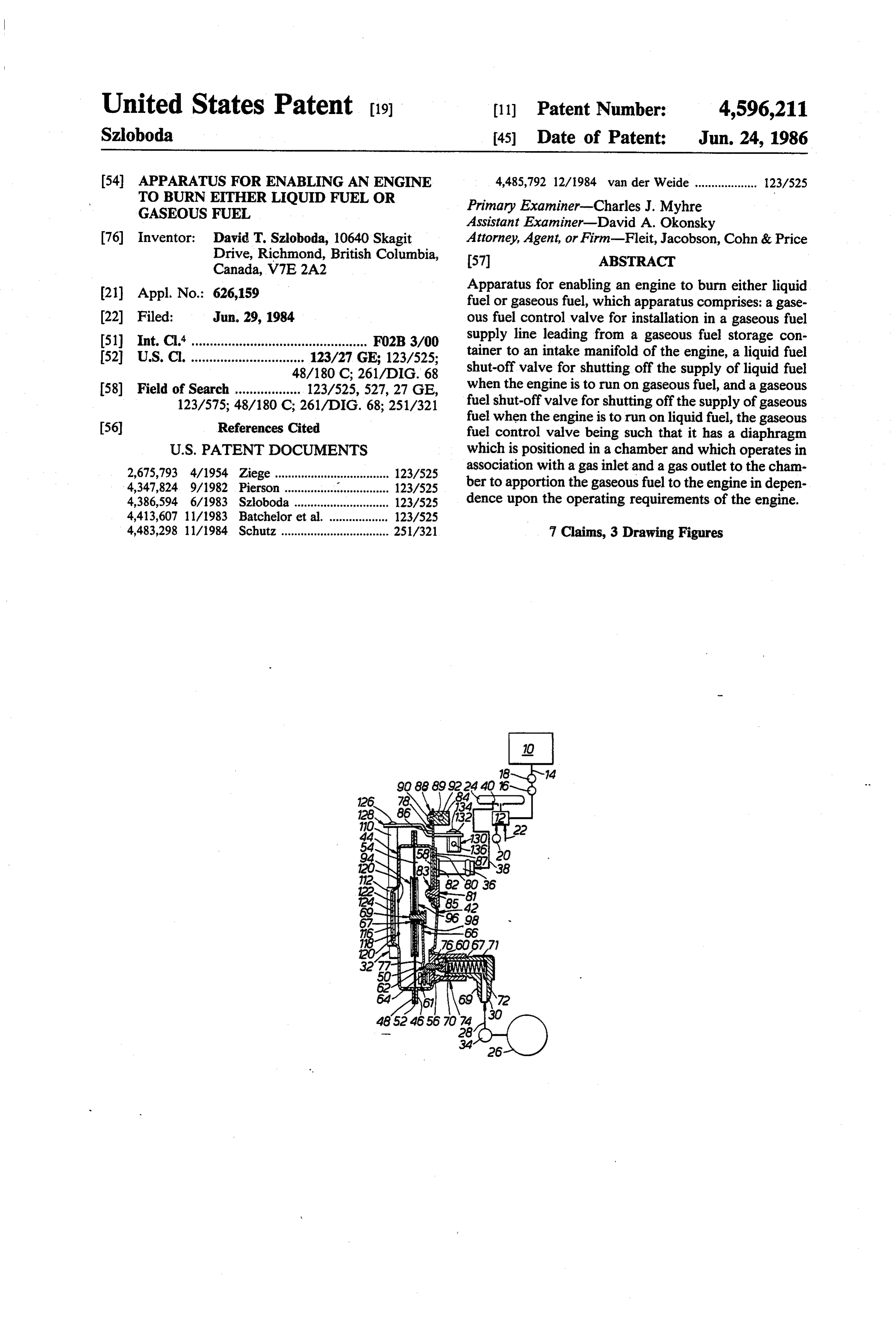
United States Patent (19) 11 Patent Number: 4,596,211 Szloboda 45 Date of Patent: Jun. 24, 1986 54 APPARATUS FOR ENABLING AN ENGINE 4,485,792 12/1984 van der Weide ................... 123/525 TO BURN EITHER LIQUID FUELOR Primary Examiner-Charles J. Myhre
GASEOUS FUEL
Assistant Examiner-David A. Okonsky 76) Inventor: David T. Szloboda, 10640 Skagit Attorney, Agent, or Firm-Fleit, Jacobson, Cohn & Price Drive, Richmond, British Columbia, 57 ABSTRACT
Canada, V7E 2A2 21 Appl. No.: 626,159 Apparatus for enabling an engine to burn either liquid fuel orgaseous fuel, which apparatus comprises: a gase 22) Filed: Jun. 29, 1984 ous fuel control valve for installation in a gaseous fuel (51) int.C.'................................................ FO2B 3/00 supply line leading from a gaseous fuel storage con (52) U.S. C. ............................... 123/27 GE; 123/525; tainer to an intake manifold of the engine, a liquid fuel 48/180 C; 261/DIG. 68 shut-off valve for shutting off the supply of liquid fuel 58) Field of Search .................. 123/525,527, 27 GE, when the engine is to run on gaseous fuel, and a gaseous 123/575; 48/180 C; 261/DIG. 68; 251/321 fuel shut-off valve for shutting off the supply of gaseous fuel when the engine is to run on liquid fuel, the gaseous 56) References Cited fuel control valve being such that it has a diaphragm
2,675,793 4/1954 Ziege ..... ... 123/525 association with a gas inlet and a gas outlet to the cham 4,347,824. 9/1982 Pierson ...... ... 123/525 ber to apportion the gaseous fuel to the engine in depen 4,386,594 6/1983 Szloboda ............................. 123/525 dence upon the operating requirements of the engine. 4,413,607 11/1983 Batchelor et al. .................. 123/525 4,483.298 11/1984 Schutz ................................. 251/321 7 Claims, 3 Drawing Figures
Page 2
Drawing sheet — no readable text.
Page 3
nected with respect to the diaphragm that movement
APPARATUS FOR ENABLNG AN ENGINE TO of the diaphragm in a direction tending to decrease BURN EITHER LIQUID FUEL OR GASEOUS the size of the chamber increases the size of the inlet FUEL and movement of the diaphragm in a direction tend ing to increase the size of the chamber decreases the
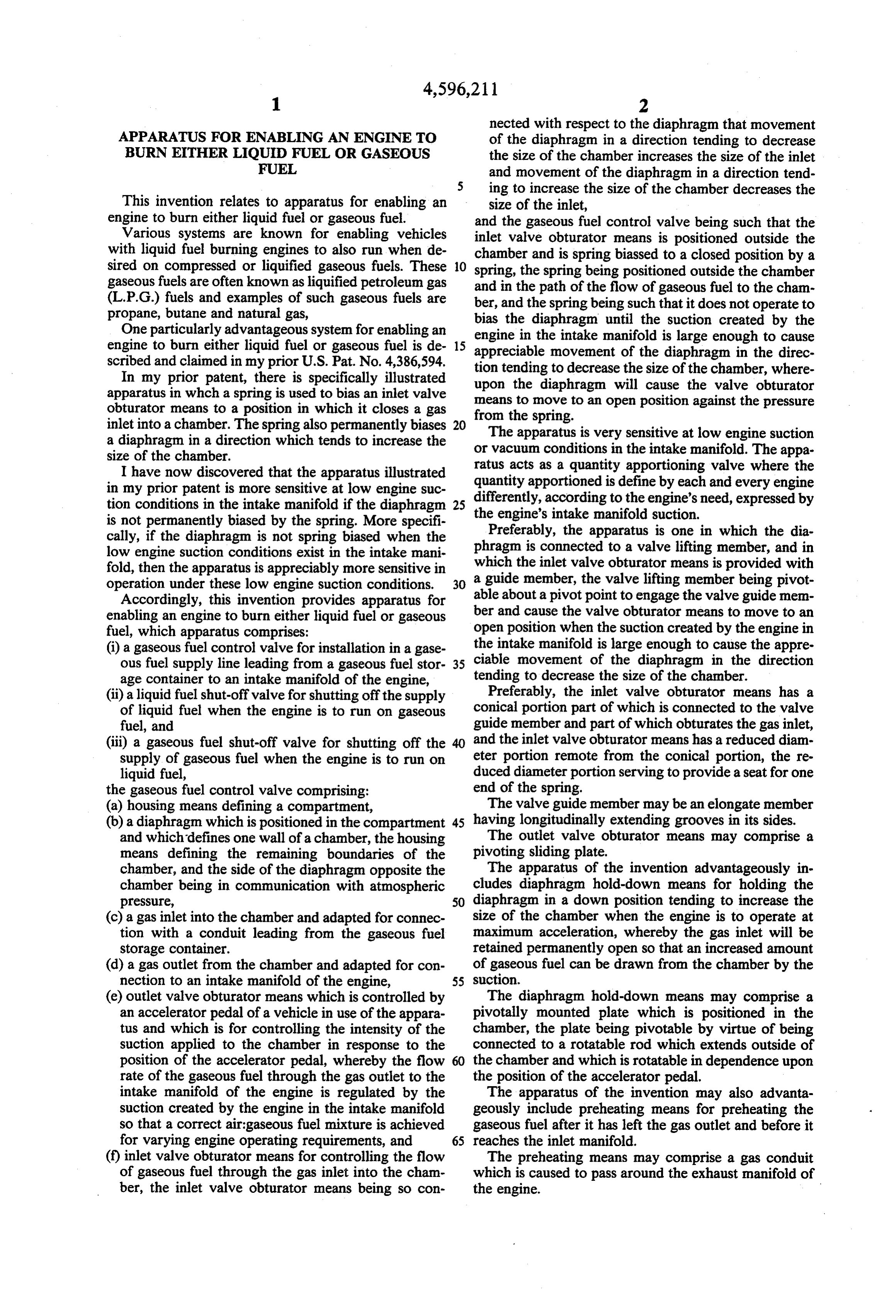
This invention relates to apparatus for enabling an size of the inlet, engine to burn either liquid fuel or gaseous fuel. and the gaseous fuel control valve being such that the Various systems are known for enabling vehicles inlet valve obturator means is positioned outside the with liquid fuel burning engines to also run when de sired on compressed or liquified gaseous fuels. These O chamber and is spring biassed to a closed position by a spring, the spring being positioned outside the chamber gaseous fuels are often known as liquified petroleum gas and in the path of the flow of gaseous fuel to the cham (L.P.G.) fuels and examples of such gaseous fuels are ber, and the spring being such that it does not operate to propane, butane and natural gas,
One particularly advantageous system for enabling an bias engine the diaphragm until the suction created by the in the intake manifold is large enough to cause engine to burn either liquid fuel or gaseous fuel is de 15 appreciable scribed and claimed in my prior U.S. Pat. No. 4,386,594. tion tending movement to decrease of the diaphragm in the direc the size of the chamber, where
In my prior patent, there is specifically illustrated upon the diaphragm will cause the valve obturator apparatus in which a spring is used to bias an inlet valve means to move to an open position against the pressure obturator means to a position in which it closes a gas from the spring.
inlet into a chamber. The spring also permanently biases 20 a diaphragm in a direction which tends to increase the orThe apparatus is very sensitive at low engine suction vacuum conditions in the intake manifold. The appa size of the chamber.
I have now discovered that the apparatus illustrated quantityratus acts as a quantity apportioning valve where the in my prior patent is more sensitive at low engine suc differently, apportioned is define by each and every engine tion conditions in the intake manifold if the diaphragm 25 the engine'saccording to the engine's need, expressed by intake manifold suction.
is not permanently biased by the spring. More specifi Preferably, the apparatus is one in which the dia cally, if the diaphragm is not spring biased when the phragm is connected to a valve lifting member, and in low engine suction conditions exist in the intake mani fold, then the apparatus is appreciably more sensitive in awhich the inlet valve obturator means is provided with guide member, the valve lifting member being pivot operation under these low engine suction conditions. 30 able about a pivot point to engage the valve guide mem Accordingly, this invention provides apparatus for ber and cause the valve obturator means to move to an enabling an engine to burn either liquid fuel or gaseous fuel, which apparatus comprises: open position when the suction created by the engine in (i) a gaseous fuel control valve for installation in a gase the intake manifold is large enough to cause the appre ous fuel supply line leading from a gaseous fuel stor 35 ciable movement of the diaphragm in the direction age container to an intake manifold of the engine, tending to decrease the size of the chamber. (ii) a liquid fuel shut-off valve for shutting off the supply Preferably, the inlet valve obturator means has a of liquid fuel when the engine is to run on gaseous conical portion part of which is connected to the valve fuel, and guide member and part of which obturates the gas inlet, (iii) a gaseous fuel shut-off valve for shutting off the and the inlet valve obturator means has a reduced diam supply of gaseous fuel when the engine is to run on eter portion remote from the conical portion, the re liquid fuel, duced diameter portion serving to provide a seat for one the gaseous fuel control valve comprising: end of the spring.
(a) housing means defining a compartment, The valve guide member may be an elongate member (b) a diaphragm which is positioned in the compartment 45 having longitudinally extending grooves in its sides. and which defines one wall of a chamber, the housing The outlet valve obturator means may comprise a means defining the remaining boundaries of the pivoting sliding plate.
chamber, and the side of the diaphragm opposite the The apparatus of the invention advantageously in chamber being in communication with atmospheric cludes diaphragm hold-down means for holding the pressure, 50 diaphragm in a down position tending to increase the (c) a gas inlet into the chamber and adapted for connec size of the chamber when the engine is to operate at tion with a conduit leading from the gaseous fuel maximum acceleration, whereby the gas inlet will be storage container. retained permanently open so that an increased amount (d) a gas outlet from the chamber and adapted for con of gaseous fuel can be drawn from the chamber by the nection to an intake manifold of the engine, 55 suction.
(e) outlet valve obturator means which is controlled by The diaphragm hold-down means may comprise a an accelerator pedal of a vehicle in use of the appara pivotally mounted plate which is positioned in the tus and which is for controlling the intensity of the chamber, the plate being pivotable by virtue of being suction applied to the chamber in response to the connected to a rotatable rod which extends outside of position of the accelerator pedal, whereby the flow the chamber and which is rotatable in dependence upon rate of the gaseous fuel through the gas outlet to the the position of the accelerator pedal. intake manifold of the engine is regulated by the The apparatus of the invention may also advanta suction created by the engine in the intake manifold geously include preheating means for preheating the so that a correct air-gaseous fuel mixture is achieved gaseous fuel after it has left the gas outlet and before it for varying engine operating requirements, and 65 reaches the inlet manifold.
(f) inlet valve obturator means for controlling the flow The preheating means may comprise a gas conduit of gaseous fuel through the gas inlet into the cham which is caused to pass around the exhaust manifold of ber, the inlet valve obturator means being so con the engine.
Page 4
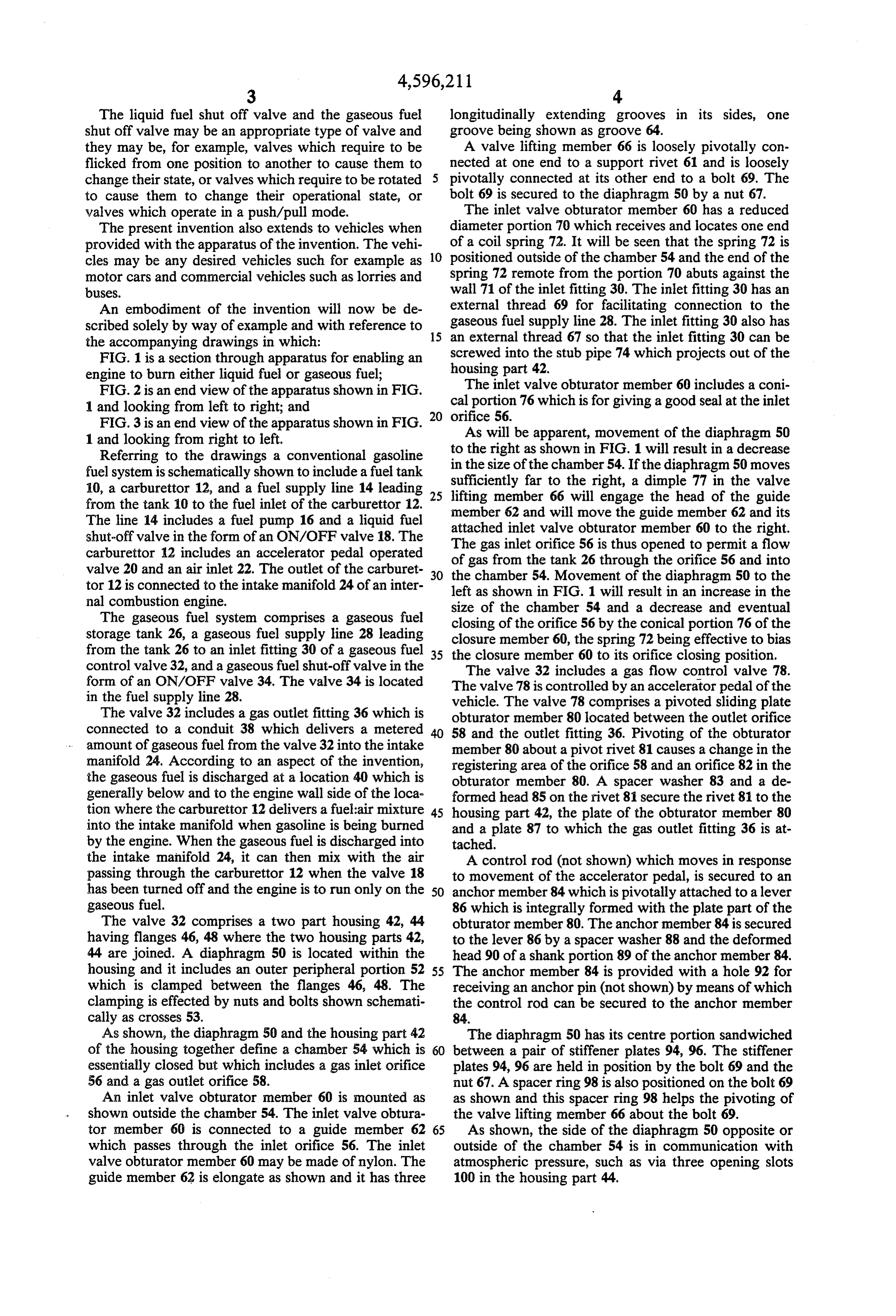
The liquid fuel shut off valve and the gaseous fuel longitudinally extending grooves in its sides, one shut off valve may be an appropriate type of valve and groove being shown as groove 64.
they may be, for example, valves which require to be A valve lifting member 66 is loosely pivotally con flicked from one position to another to cause them to nected at one end to a support rivet 61 and is loosely change their state, or valves which require to be rotated pivotally connected at its other end to a bolt 69. The to cause them to change their operational state, or bolt 69 is secured to the diaphragm 50 by a nut 67. valves which operate in a push/pull mode. The inlet valve obturator member 60 has a reduced The present invention also extends to vehicles when diameter portion 70 which receives and locates one end provided with the apparatus of the invention. The vehi of a coil spring 72. It will be seen that the spring 72 is cles may be any desired vehicles such for example as 10 positioned outside of the chamber 54 and the end of the motor cars and commercial vehicles such as lorries and spring 72 remote from the portion 70 abuts against the buses. wall 71 of the inlet fitting 30. The inlet fitting 30 has an An embodiment of the invention will now be de external thread 69 for facilitating connection to the scribed solely by way of example and with reference to 15 gaseous fuel supply line 28. The inlet fitting 30 also has the accompanying drawings in which: an external thread 67 so that the inlet fitting 30 can be FIG. 1 is a section through apparatus for enabling an screwed housing into the stub pipe 74 which projects out of the part 42.
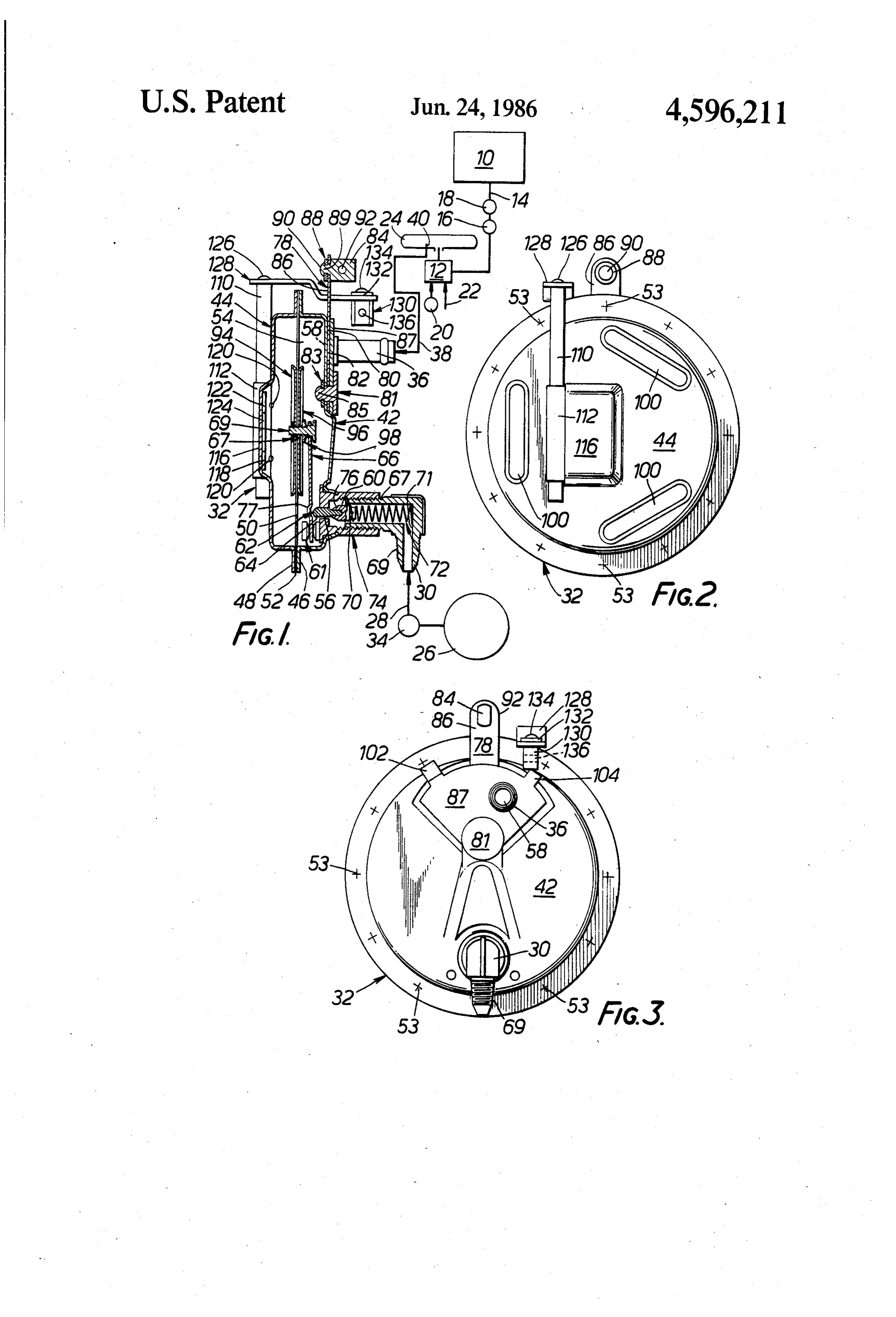
engine to burn either liquid fuel or gaseous fuel;
FIG. 2 is an end view of the apparatus shown in FIG. calThe inlet valve obturator member 60 includes a coni portion 76 which is for giving a good seal at the inlet 1 and looking from left to right; and
FIG. 3 is an end view of the apparatus shown in FIG. 20 orifice
will be apparent, movement of the diaphragm 50 1 and looking from right to left.
Referring to the drawings a conventional gasoline to the right as shown in FIG. 1 will result in a decrease fuel system is schematically shown to include a fuel tank in the size of the chamber 54. If the diaphragm 50 moves 10, a carburettor 12, and a fuel supply line 14 leading 25 sufficiently lifting member far to the right, a dimple 77 in the valve 66 will engage the head of the guide from the tank 10 to the fuel inlet of the carburettor 12, member 62 and will move the guide member 62 and its
The line 14 includes a fuel pump 16 and a liquid fuel attached shut-off valve in the form of an ON/OFF valve 18. The inlet valve obturator member 60 to the right. carburettor 12 includes an accelerator pedal operated The gas inlet orifice 56 is thus opened to permit a flow valve 20 and an air inlet 22. The outlet of the carburet 30 of gas from the tank 26 through the orifice 56 and into tor 12 is connected to the intake manifold 24 of an inter the chamber 54. Movement of the diaphragm 50 to the left as shown in FIG. 1 will result in an increase in the nal combustion engine. size of the chamber 54 and a decrease and eventual The gaseous fuel system comprises a gaseous fuel storage tank 26, a gaseous fuel supply line 28 leading closing closure of the orifice 56 by the conical portion 76 of the member 60, the spring 72 being effective to bias from the tank 26 to an inlet fitting 30 of a gaseous fuel 35 the closure member 60 to its orifice closing position. control valve 32, and a gaseous fuel shut-off valve in the The valve 32 includes a gas flow control valve 78. form of an ON/OFF valve 34. The valve 34 is located The valve 78 is controlled by an accelerator pedal of the in the fuel supply line 28. vehicle. The valve 78 comprises a pivoted sliding plate The valve 32 includes a gas outlet fitting 36 which is obturator member 80 located between the outlet orifice connected to a conduit 38 which delivers a metered 58 and the outlet fitting 36. Pivoting of the obturator amount of gaseous fuel from the valve 32 into the intake member 80 about a pivot rivet 81 causes a change in the manifold 24. According to an aspect of the invention, registering area of the orifice 58 and an orifice 82 in the the gaseous fuel is discharged at a location 40 which is obturator member 80. A spacer washer 83 and a de generally below and to the engine wall side of the loca formed head 85 on the rivet 81 secure the rivet 81 to the tion where the carburettor 12 delivers a fuel:air mixture 45 housing part 42, the plate of the obturator member 80 into the intake manifold when gasoline is being burned and a plate 87 to which the gas outlet fitting 36 is at by the engine. When the gaseous fuel is discharged into tached.
the intake manifold 24, it can then mix with the air A control rod (not shown) which moves in response passing through the carburettor 12 when the valve 18 to movement of the accelerator pedal, is secured to an has been turned off and the engine is to run only on the 50 anchor member 84 which is pivotally attached to a lever gaseous fuel. 86 which is integrally formed with the plate part of the The valve 32 comprises a two part housing 42, 44 obturator member 80. The anchor member 84 is secured having flanges 46, 48 where the two housing parts 42, to the lever 86 by a spacer washer 88 and the deformed 44 are joined. A diaphragm 50 is located within the head 90 of a shank portion 89 of the anchor member 84. housing and it includes an outer peripheral portion 52 55 The anchor member 84 is provided with a hole 92 for which is clamped between the flanges 46, 48. The receiving an anchor pin (not shown) by means of which clamping is effected by nuts and bolts shown schemati the control rod can be secured to the anchor member cally as crosses 53. 84.
As shown, the diaphragm 50 and the housing part 42 The diaphragm 50 has its centre portion sandwiched of the housing together define a chamber 54 which is 60 between a pair of stiffener plates 94, 96. The stiffener essentially closed but which includes a gas inlet orifice plates 94, 96 are held in position by the bolt 69 and the 56 and a gas outlet orifice 58. nut 67. A spacer ring 98 is also positioned on the bolt 69 An inlet valve obturator member 60 is mounted as as shown and this spacer ring 98 helps the pivoting of shown outside the chamber 54. The inlet valve obtura the valve lifting member 66 about the bolt 69. tor member 60 is connected to a guide member 62 65 As shown, the side of the diaphragm 50 opposite or which passes through the inlet orifice 56. The inlet outside of the chamber 54 is in communication with valve obturator member 60 may be made of nylon. The atmospheric pressure, such as via three opening slots guide member 62 is elongate as shown and it has three 100 in the housing part 44.
Page 5
It is believed that the best location to mount the valve In use of the valve 32, it is important when switching 32 is on the engine as close as possible to a position from gasoline to gaseous fuel to use up all of the gaso which is vertically in line with the carburettor control line that remains in the carburettor 12 before opening arm. The control rod is then connected at its end oppo the gaseous fuel valve 34. If this is not done, the engine site the anchor member 84 to the carburettor control will receive both gaseous fuel and gasoline and will arm (not shown). This connection of the control rod to become flooded. When switching from gaseous fuel to the carburettor control arm ensures that an appropriate gasoline, it may be necessary to usually start one or amount of air for admixture with the gas coming from twice to cause the gasoline pump to pump gasoline into the conduit 38 is achieved. This position of mounting the empty carburettor.
the valve 32 will ensure that any vibration or rattling of 10 Proper operation of the valve 32 will produce a flut the engine will not cause motion which will adversely tering movement of the valve lifting member 66 and the affect operation of the valve 32. diaphragm 50. At high speeds, the "fluttering' move The manner of installing the valve 32 in a vehicle may ment will result in a rattling sound inside the valve 32 be as follows. The vehicle engine is first run on gasoline which can be detected by use of a listening device, to warm it up until the automatic choke opens. Then, 15 indicating proper functioning of the valve 32. Gaseous the gasoline line 14 is closed by operation of the ON/- fuel entering the chamber 54 through the orifice 56 will OFF valve 18. The engine will continue to burn gaso expand and will increase the pressure within the cham line until all of the gasoline in the carburettor 12 is ber 54. At the same time, the suction or vacuum present completely used up. Then, the user connects the control in the intake manifold 24, communicated with the rod to the accelerator linkage and preferably to the 20 chamber 54 via the conduit 38, the inlet fitting 36, the control arm on the carburettor. valve orifice 82 in the obturator member 80 and the The obturator member 80 is initially closed. Then orifice 58, will tend to lower the pressure within the mouth suction is applied on the conduit 38 and at the chamber 54. Thus, there are two opposite forces acting same time the obturator member 80 is set to a slightly on the same side of the diaphragm 50. The expanding open or approximate idling speed position. Next, the 25 gas from the orifice 56 will act to force the diaphragm lower end of the conduit 38 is positioned inside the 50 to the left as shown in FIG. 1, and the suction will act intake manifold 24, substantially immediately below the to cause the diaphragm 50 to move to the right as opening leading from the carburettor 12, on the engine . shown in FIG. 1. As the expanding gas forces the dia block side thereof. This may easily be done by inserting phragm 50 to the left, the spring 72 causes the closure a piece of copper pipe of appropriate length through a 30 member 60 to close the orifice 56. This prevents the gas brass nipple which is adapted to thread into an opening entering the chamber 56 and the suction then becomes provided in the manifold 24, such that when the nipple the dominant force controlling the movement of the is tightened, the inner end of the copper pipe is properly diaphragm 50. In use of the valve 32, the diaphragm 50 placed below the opening leading from the carburettor will be constantly moving or fluttering as the gas is 12, to the engine block side of the intake manifold 24. A 35 apportioned.
short length of the copper pipe is allowed to project The valve 32 may be regarded as a quantity appor upwardly through the nipple, for connection to a hose tioning valve. The quantity apportioned may be defined which forms the remaining part of the conduit 38 lead by each and every engine differently, according to the ing from the gas outlet fitting 36 to the piece of copper engine's need as expressed by its intake manifold suction plpe. or vacuum. The valve 32 can be used by a wide variety The gaseous fuel storage tank 26 may be located at of internal cumbustion engines including gasoline, die any convenient and legal location within the vehicle. As sel, turbine, jet and Wankel engines for example. The is well known, the tank 26 will include liquified gaseous engines can be part of vehicles or they can be stationery, fuel and the fuel above the liquid level (not shown) in for example for use in industrial applications. The valve the tank 26 will be in gaseous form. The gaseous fuel 45 32 is extremely accurate at low engine intake manifold supply line 28 is connected between the storage tank 26 suction conditions mainly because it has no spring in the and the inlet fitting 30 as shown. chamber acting on the centre of the disphragm 50. After such installation has been accomplished, the The valve 32 may eliminate the need for a pressure ON/OFF valve 34 is opened. The engine is started and regulating valve in the outlet of the tank 26 and the any necessary adjustments are made to set the idling 50 known associated problem of icing caused by the de position of the obturator member 80. Then, the connec compression of the gas. The expansion through the tion is made between the control rod and the anchor small orifice of a pressure regulator valve results in a member 84. The obturator member 80 will require the decrease in temperature of the gas to a level at which amount of gas needed for different sizes of engines. If the gas freezes solid. This is clearly undesirable and this desired, the obturator member 80 can be adjusted not to 55 problem is obviated or reduced by the present inven open completely at maximum r.p.m., but only as desired tion.
for maximum fuel efficiency at any speed. The pivoting The valve 32 is also such that it facilitates the reduc movement of the obturator member 80 can be regulated tion or obviation of unwanted engine exhaust emissions by a pair of stop members 102, 104 formed integrally such as carbon dioxide. Also, adjustment of an engine with the plate 87. after it has been fitted with the apparatus of the inven The tank 26 does not include a pressure reducing tion is not necessary.
valve in its outlet. As a result of this fact, and at least Engine operating conditions may arise in which a partially also due to the relatively close location of the kick-down facility giving sudden acceleration is re chamber 54 to the manifold 24, icing of fittings and quired. Accordingly, the valve 32 is provided with conduits should be prevented or reduced. 65 diaphragm hold-down means which operates to give a The ON/OFF valves 18, 34 are preferably readily kick-down facility. The diaphragm hold-down means available low cost valves which are adapted to be con comprises a rod 110 which is pivotally mounted to the trolled by manual choke cables. housing part 44. More specifically, the rod 110 passes
Page 6
through a raised tunnel portion 112 of the housing part storage container to an intake manifold of the en 114. The raised tunnel portion 112 extends into a further gine, raised portion 116 of the housing part 44. Inside the (ii) a liquid fuel shut-off valve for shutting off the housing part 44 and in the concave recess formed by the supply of liquid fuel when the engine is to run on raised portion 116 is located a plate 118. The plate 118 gaseous fuel, and is bolted by two fastening bolts 120 directly to the rod (iii) a gaseous fuel shut-off valve for shutting off the 110 so that the plate 118 stops the rod 110 from pulling supply of gaseous fuel when the engine is to run on out of the housing part 44. The upper edge 122 of the liquid fuel, plate 118 is provided with a central cut-out 124 so that the gaseous fuel control valve comprising: the plate 118 does not foul the nut 67. 10 (a) housing means defining a compartment, The rod 110 has a deformed head 126 by means of (b) a diaphragm which is positioned in the compart which the rod 110 is secured to a kick-down lever 128. ment and which defines one wall of a chamber, the The lever 128 is cranked as shown and the other end of housing means defining the remaining boundaries the lever 128 is provided with a pivotally connected of the chamber, and the side of the diaphragm anchor member 130. The anchor member 130 is held in 15 opposite the chamber being in communication with position by a washer 132 and a deformed head portion atmospheric pressure, 134 of the anchor member 130. The anchor member 130 (c) a gas inlet into the chamber and adapted for con is provided with a hole 136 for receiving an anchor pin nection with a conduit leading from the gaseous (not shown) by means of which a kick-down linkage to fuel storage container, the accelerator pedal of a vehicle may be connected to 20 (d) a gas outlet from the chamber and adapted for the anchor member 130. connection to an intake manifold of the engine, When maximum acceleration from the engine is re (e) outlet valve obturator means which is controlled quired, the accelerator pedal will be kicked down and by an accelerator pedal of a vehicle in use of the the rod 110 will rotate consequent upon pivotting of the apparatus and which is for controlling the intensity lever 128. The plate 118 will then pivot from its rest 25 of the suction applied to the chamber in response to position in the concave recess defined by the raised the position of the accelerator pedal, whereby the portion 116 of the housing part 44 and it will hold the flow rate of the gaseous fuel through the gas outlet diaphragm 50 in its downward position so that the dia to the intake manifold of the engine is regulated by phragm 50 will not be able to be moved upwardly by the suction created by the engine in the intake virture of expansion of the compressed gas passing 30 manifold so that a correct air: gaseous fuel mixture through the orifice 56 into the chamber 54. This will is achieved for varying engine operating require allow the vacuum in the gas outlet fitting 36 to draw off ments, and more gas from the chamber 54 than would be the case if (f) inlet valve obturator means for controlling the the diaphragm 50 were allowed to move upwardly and flow of gaseous fuel through the gas inlet into the thus increase the size of the chamber 54. 35 chamber, the inlet valve obturator means being so Although not shown in the drawings, the apparatus connected with respect to the diaphragm that may be used with preheating means for preheating the movement of the diaphragm in a direction tending gaseous fuel after it has left the gas outlet 36 and before to decrease the size of the chamber increases the it reaches the inlet manifold 24. The preheating means size of the inlet and movement of the diaphragm in may be in the form of an extension of the conduit 38 so a direction tending to increase the size of the cham that it forms a coil around an exhaust manifold of the ber decreases the size of the inlet, engine. Because the exhaust manifold is hot, it will heat and the gaseous fuel control valve being such that the the gas in the conduit 38. This gas in the conduit 38 may inlet valve obturator means is positioned outside the be almost at freezing point due to the fact that it will chamber and is spring biassed to a closed position by a have expanded considerably from when it was in the 45 spring, the spring being positioned outside the chamber tank 26. Considerably further expansion of the gas oc and in the path of the flow of gaseous fuel to the cham curs in the coil than would take place only in the intake ber, and the spring being such that it does not operate to manifold 24. This expanded gas is thus more easily able bias the diaphragm until the suction created by the to satisfy the suction in the intake manifold 24 and so engine in the intake manifold is large enough to cause there is less of a suction acting on the bottom of the 50 appreciable movement of the diaphragm in the direc diaphragm 50. This in turn means that a smaller amount tion tending to decrease the size of the chamber, where of gas is required to be withdrawn from the chamber 54, upon the diaphragm will cause the valve obturator which in turn gives greater fuel efficiency. means to move to an open position against the pressure It is to be appreciated that the embodiment of the from the spring.
invention described above with reference to the accom 55 2. Apparatus according to claim 1 in which the outlet panying drawings has been given by way of example valve obturator means comprises a pivotting sliding only and that modifications may be effected and any plate.
desired stated parts may be omitted. Thus, for example, 3. Apparatus according to claim 1 and including dia the tank 26 may have one or more heat loss compensa phragm hold-down means for holding the diaphragm in tors to allow driving in all weather conditions including 60 a down position tending to decrease the size of the sub-zero temperatures. Also various adjustment screws chamber when the engine is to operate at maximum may be provided, either on the valve 32 or, more usu acceleration, whereby the gas inlet will be retained ally, on the connecting rods and levers. permanently open so that an increased amount of gase I claim: o ous fuel can be drawn from the chamber by the suction. 1. Apparatus for enabling an engine to burn either 65 4. Apparatus according to claim 3 in which the dia liquid fuel or gaseous fuel, which apparatus comprises: phragm hold-down means comprises a pivotally (i) a gaseous fuel control valve for installation in a mounted plate which is positioned in the chamber, the gaseous fuel supply line leading from a gaseous fuel plate being pivotable by virtue of being connected to a
Page 7
rotatable rod which extends outside of the chamber and ciable movement of the diaphragm in the direction which is rotatable in dependence upon the position of tending to decrease the size of the chamber. 6. Apparatus according to claim 5 in which the inlet the accelerator pedal. valve obturator means has a conical portion part of 5. Apparatus according to claim 1 in which the dia which is connected to the valve guide member and part phragm is connected to a valve lifting member, and in of which obturates the gas inlet, and in which the inlet which the inlet valve obturator means is provided with valve obturator means has a reduced diameter portion remote from the conical portion, the reduced diameter a guide member, the valve lifting member being pivot portion serving to provide a seat for one end of the able about a pivot point to engage the valve guide mem O spring.
ber and cause the valve obturator means to move to an 7. Apparatus according to claim 6 in which the valve guide member is an elongate member having longitudi open position when the suction created by the engine in nally extending grooves in its sides. the intake manifold is large enough to cause the appre k
Provenance
- Collection
- Cited prior art
- Original PDF
- patentimages.storage.googleapis.com →
- Filed
- 1984-06-29
- Pages
- 7
- Method
- pdftotext (the PDF's own text layer) + pdftoppm 300dpi page scans
- Source
- Google Patents bibliographic record
- Granted
- 1986-06-24
- Inventors
- David T. Szloboda
- Transcribed from
- patentimages.storage.googleapis.com →