patent · US4586489
Semi-concentrating solar energy collector
6 May 1986
Page 1 — bibliographic record
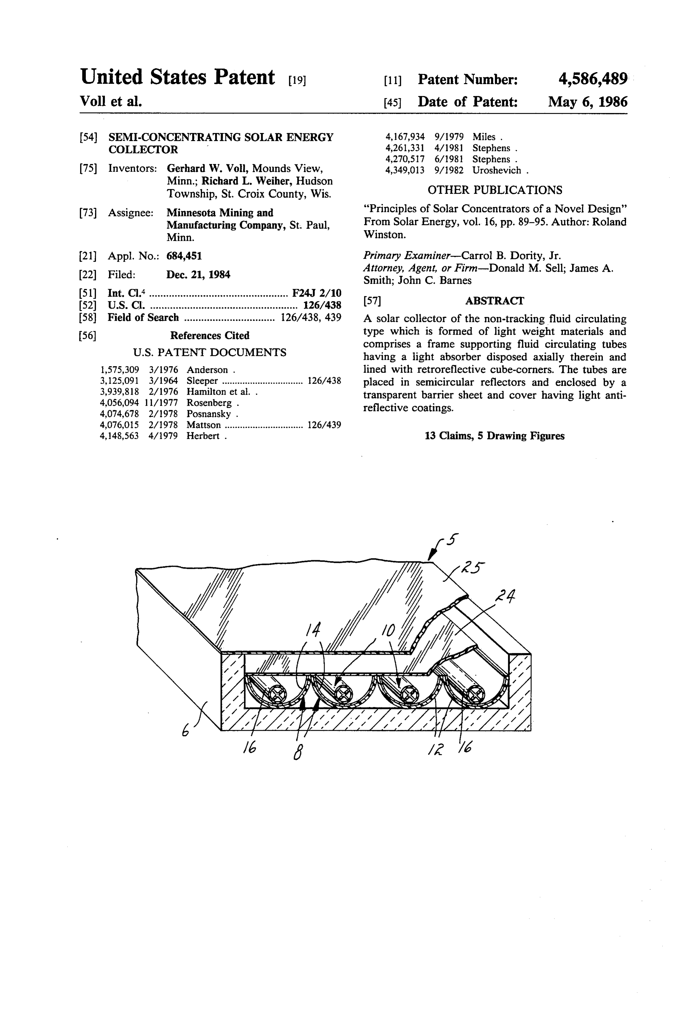
United States Patent (19) 11) Patent Number: 4,586,489 Voll et al. 45 Date of Patent: May 6, 1986 (54) SEMI-CONCENTRATING SOLAR ENERGY 4,167,934 9/1979 Miles. COLLECTOR 4,261,331 4/1981 Stephens .
75) Inventors: Gerhard W. Voll, Mounds View, 4,349,013 9/1982 Uroshevich . Minn.; Richard L. Weiher, Hudson
Township, St. Croix County, Wis. OTHER PUBLICATIONS 73 Assignee: Minnesota Mining and "Principles of Solar Concentrators of a Novel Design” Manufacturing Company, St. Paul, From Solar Energy, vol. 16, pp. 89-95. Author: Roland Minn. Winston.
21 Appl. No.: 684,451 Primary Examiner-Carrol B. Dority, Jr. 22 Filed: Dec. 21, 1984 Attorney, Agent, or Firm-Donald M. Sell; James A. Smith; John C. Barnes 51) Int. Cl." ................................................. F24, 2/10 57 ABSTRACT
58) A solar collector of the non-tracking fluid circulating 56) References Cited type which is formed of light weight materials and
comprises a frame supporting fluid circulating tubes having a light absorber disposed axially therein and 1,575,309 3/1976 Anderson . lined with retroreflective cube-corners. The tubes are 3,125,091 3/1964 Sleeper ................................ 26/438 placed in semicircular reflectors and enclosed by a 3,939,818 2/1976 Hamilton et al. . transparent barrier sheet and cover having light anti 4,056,094 11/1977 Rosenberg . reflective coatings.
4,076,015 2/1978 Mattson ............................... 126/439 4,148,563 4/1979 Herbert . 13 Claims, 5 Drawing Figures
Sea
Page 2
Drawing sheet — no readable text.
Page 3
Drawing sheet — no readable text.
Page 4
appear between the sun and the absorber. U.S. Pat. No.
SEM-CONCENTRATING SOLARENERGY 4,148,563, issued Apr. 10, 1979, to E. Herbert discloses COLLECTOR two mating collector elements utilizing V-shaped ridges with a 90 degree included angle. When a film of liquid
BACKGROUND OF THE INVENTION 5 is disposed between the mating surfaces with the V 1. Field of the Invention shaped ridges, light is allowed to pass and heat up the This invention relates to solar energy collectors, and liquid, but when the liquid reaches a certain tempera in one aspect, to an improved solar energy collector ture the liquid vaporizes, causing the incoming light to which is plastic, lightweight, semi-concentrating, non 10 be reflected by the V-shaped ridges or prisms. Another tracking and of the fluid circulating type for use in piece of prior art which is specifically related to the various heating applications. "light valve' is U.S. Pat. No. 4,056,094, issued Nov. 1, 2. Description of the Prior Art 1977, to P. Rosenberg. This patent shows a valve for a Fluid circulating solar heating systems utilize a col flat plate collector utilizing rows of V-shaped ridges on lector for changing the sun's energy to heat, a heat the light transmitting panel which is spaced from the exchanger for transferring the heat energy to a circulat 15 absorber plate and through which space the heat trans ing medium via connecting pipes, manifolds, circulating fer fluid is caused to flow. When the fluid is in the space pumps, and the associated controls for such systems. A the light is transmitted and when the fluid is drained desirable feature for a solar energy collector is an effi away, the V-shaped ridges cause total internal reflec cient absorber of the solar energy. One such absorber is 20 tion of the light so it is not allowed to pass through the a dark vaned absorber disposed in a fluid circulating transmitting panel to the absorber. The use of linear tube such that as the sun's energy is changed to heat. V-shaped ridges or prisms with the facets at 45° with energy on the absorber the circulating fluid will absorb the top surface require frequent adjustment of a flat the heat. Because of the use of plastic, however, it is plate solar collector throughout the year, see Column 8, necessary, in the event of power failure or when the lines 28 to 48.
system is allowed to drain down, that the absorber will 25 The present invention overcomes the deficiencies of not become too hot and melt the tube. Further, to avoid the prior art and provides a highly efficient solar energy the necessity of tracking, the reflectors around the ab collector sorber are not parabolic reflectors having a focus, and light valvewhich has a unique automatic shutdown or system to eliminate high stagnation tempera the design of the system should be such that ambient tures, and one which is designed such that no tracking heat around the absorbers cannot be easily lost by con 30 or adjustment or alignment with the sun is necessary to vective currents.
A typical heating element for solar energy is de tective obtain its near maximum efficiency and utilize its pro scribed in U.S. Pat. No. 1,575,309, issued to W. A. An lating systemsfeatures. The collector is usable with fluid circu derson, Mar. 2, 1926. This patent discloses a solar heat "drain-back” hotand is particularly compatible with water systems.
ing element using a parabolic reflector, in the center of 35 which was mounted a light absorbing heating member SUMMARY OF THE INVENTION 21 positioned to absorb the sun's rays striking the reflec tor. The heating member 21 was placed in a transparent This invention relates to a solar collector comprising tube through which water could be circulated, resulting an insulative frame member enclosing a plurality of in the heating of the water by the heating member. A transparent tubes for circulating the heat transfer fluid, system of this nature would necessarily have to be sup an efficient solar energy absorber disposed in the tubes, ported to track the movement of the sun to be efficient a long reflector of generally semi-circular cross section more than a limited period each day. surrounding each of the tubes, a light transmissive cov Another similar patent teaching the use of an ab ering over the reflectors to maintain the heat energy sorber within a transparent tube positioned at the focus 45 adjacent the tubes and free from loss due to ambient of a reflector is U.S. Pat. No. 4,074,678, issued Feb. 21, convective currents, and an outer protective skin of 1978, to M. Posnansky. transparent material.
The present invention utilizes a generally semi-cylin The transparent tubes have an internal covering con drical reflector positioned about each of a plurality of taining cube corner prisms affording total internal re clear plastic tubes for the heat transfer medium. Such 50 flection in the areas of each of the cube corner prisms to semi-cylindrical reflectors do not focus light striking block light passing through the tubes from reaching the the reflector to a predetermined point and thus tracking absorber disposed centrally with respect to the tubes is unnecessary. when the heat transmitting fluid is drained from the Another important part of an efficient, all plastic tubes.
collector is the protection of the components from ex 55 The frame of the solar energy collector of the present ceedingly high temperatures. This is necessary particu invention is a large trough formed of insulative styrene larly if there is a power failure or the system is drained or similar light-weight material within which is a plural for other reasons. Protection of this sort is accom ity of parallel extending reflectors and clear transparent plished by the use of a light blocking system or light fluid circulating tubes preferably of plastic. It is recog valve which has the effect of stopping the sunlight from nized that the frame may be made of a variety of other reaching the absorber during such periods to avoid high insulative materials, e.g., wood.
"stagnation' temperatures. Prior art related to such The barrier over the reflectors is preferably a sheet of "light valves' for solar collectors include U.S. Pat. No. material having anti-reflective surfaces permitting the 4,261,331, issued Apr. 14, 1981, to R. B. Stevens. This solar energy to readily pass through the sheet. The patent discloses a heat-sensitive optical switch which is 65 outer protective layer is formed preferably of a light operative when the temperature of the heat transfer transmissive polymeric material which has sufficient fluid gets above a predetermined value. A precipitate strength to protect the solar collectors and not become forms in the fluid, causing a light scattering layer to readily damaged or scratched by the normal environ
Page 5
mental elements, preferrably having antireflecting sur The reflectors 8 each comprise a plastic semi-cylin faces. drical member 12 having a thin reflective layer 14 lami BRIEF DESCRIPTION OF THE DRAWINGS nated or coated on the inner surface of the semi-cylin drical member. The reflectors 8 are disposed in parallel
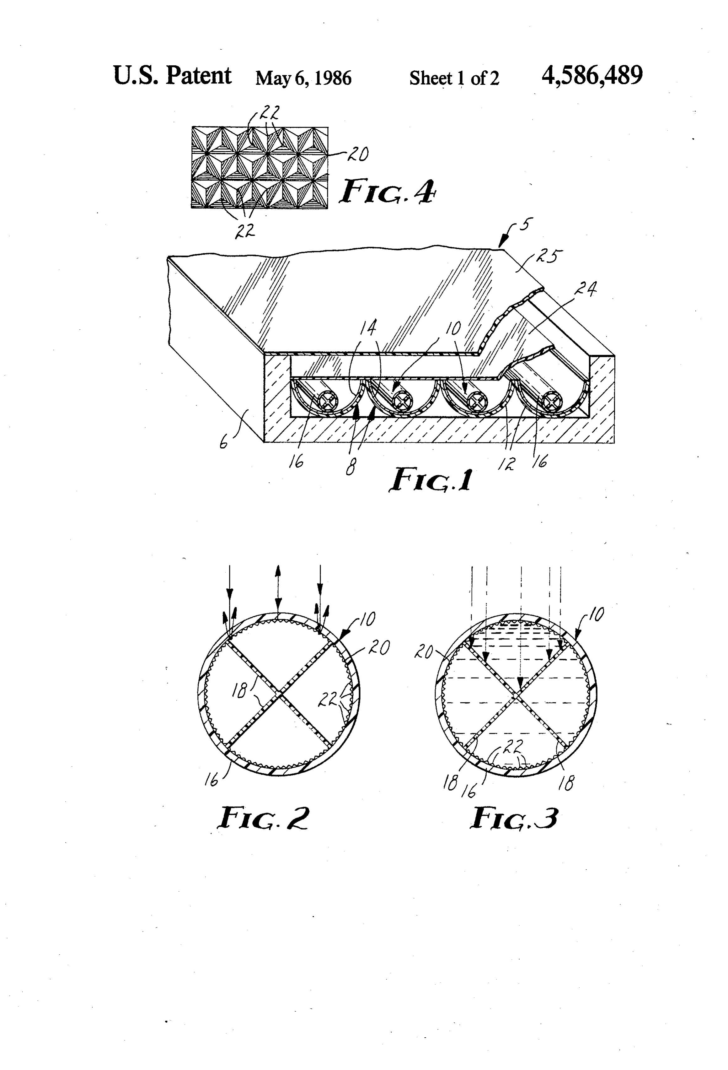
The present invention will be described in greater relationship with the open side of each reflector dis detail with reference to the accompanying drawing posed in a common plane and fitted against the adjacent wherein: reflector 8.
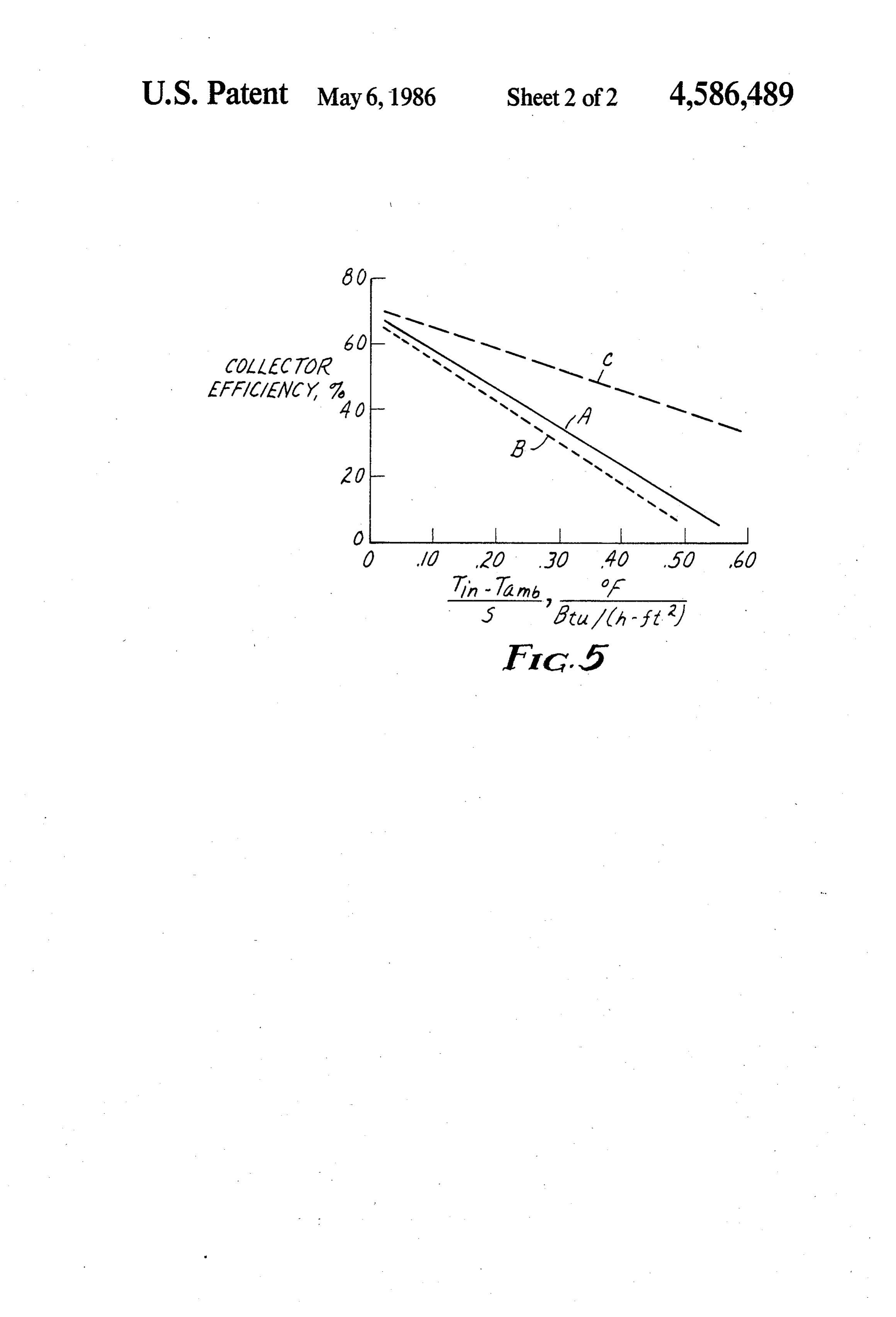
FIG. 1 is a fragmentary perspective and vertical sec Each of the plurality of heat transfer tubes 10 are tional view of the solar collector constructed in accor illustrated in greater detail in FIGS. 2 and 3, and com dance with the present invention; 10 prise clear plastic cylindrical tubes 16 in which is dis FIG. 2 is a vertical sectional view of the heat transfer posed a solar energy absorber 18 made of high tempera fluid circulating tubes of the solar collector when it is ture black plastic material such as pigmented polyaryl drained of the heat transfer fluid; sulfone or polyetherimide and having four radially di FIG. 3 is a vertical cross sectional view of the heat rected vanes. The absorber is inserted into the tube transfer fluid circulating tubes of the solar collector 15 generally coaxially thereto. The energy absorber 18 will with the heat transfer fluid disposed in the tube; be the hottest element in the solar collector, and the FIG. 4 is an enlarged planar view of the array of cube heat resulting from the absorption of the sun's energy corners lining the inner surfaces of the heat transfer on the absorber 18 will be transferred to the heat trans fluid circulating tubes; and fer fluid which would preferably be water or other FIG. 5 is a performance graph comprising perfor 20 transparent transfer liquid. The collection efficiency of mance of collectors of the present invention with a the illustrated structure is improved over conventional published performance curve. tube absorbers where the energy is absorbed at the
DESCRIPTION OF THE PREFERRED
surface of the black tube or near the surface for black
EMBODIMENTS
liquids.
25 As illustrated and preferred, the perimeter of the
Referring now to FIG. 1 there is disclosed a cross solar absorbing member 18 is four times the diameter of sectional view of the flat plate solar collector designed the tube 16. This is efficient because a one inch (2.54 according to the present invention to afford an all plas cm) diameter tube will have four inches (10.2 cm) of tic, highly efficient and light weight semi-concentrat absorber surface exposed to the heat-scrubbing circulat ing, nontracking, fluid circulating type solar collector 30 ing water for excellent heat transfer between the two. constructed with an automatic protective device to The absorber illustrated is formed of four strips joined avoid destruction resulting from high "stagnation” tem to form the X or cross shape illustrated. The area of this peratures occuring during electrical power failures or heat transfer surface is about the same as the effective other periods when the system has been drained. aperture area of the reflector 8. The collector, generally designated by the reference 35 Laminated also to the inner surface of the tube 16 is a numeral 5, has as one of its best applications the solar very thin sheet 20 of film material having on the inter heating of hot water for domestic use because it is useful nally exposed surface thereof a plurality of closely | year around, and the consumption matches well with packed cube corner prisms 22 affording retro-reflection the availability of solar energy and has a weight, size by internal reflection of light striking said cube corner and cost which are not prohibitive. In so-called "drain when the index of refraction between said prisms and : back' systems for circulation of water for hot water the interior of the tube 16 is high. This difference in the heating there is the advantage of not needing any freeze index of refraction between the film material and air protection for the heat transfer medium and only a affords internal reflection and retro-reflection of the single wall heat exchanger is needed. The collector solar rays when the water is drained from the tube 16 need not be pressurized. In these systems the fluid 45 exposing the prisms to the air in the tube. Since the drains back from the collector to a reservoir when the prisms have a low mismatch of refractive index with circulating pump stops. water, the light can penetrate the tube 16 and the sheet The present commercially available flat plate solar 20 having the retro-reflective prisms to effectively energy collectors with a high performance rating are strike the absorber 18 to absorb the heat energy from generally very costly and heavy. Most such systems are 50 the sun. With no water in the tube, as is the case when constructed from high temperature materials such as the circulating pump is offin a "drain-back' system, the metals and low iron tempered glass. Their flat energy collector tube appears white and the black solar ab absorber plates are difficult to construct. The use of sorber 18 is not seen as the solar energy is reflected. plastics in solar collectors has merit from the standpoint The heat transfer fluid tubes can alternatively be of potentially lower cost and weight and greater impact 55 formed by rolling sheets of transparent material formed resistance than glass. Presently available pigment-filled with a cube-corner surface on one face and sealing the plastic panels utilized as absorber plates for solar collec abutting edge to form a tube or molding the tubes with tion and defining the fluid circulating paths between an array of nested cube-corners on the inner surface. sealed panels have a shorter life span and do not with Forming a thermal barrier across the upper surfaces stand weathering to the extent that the higher perfor 60 of the reflectors 8 is a sheet 24 of transparent polymeric mance metal absorbing panels have. material preferably having disposed on the surfaces The solar collector of the present invention com thereof an anti-reflective coating.
prises some features of the sophisticated systems but is Extending over and spaced from the thermal barrier light weight, low cost and long lifed. The present sys sheet 24 is a cover sheet 25 of light-transmissive mate tem comprises a frame member 6 of trough shape which 65 rial which affords the protective covering for the solar thus has a recessed area in which is placed a plurality of energy collector. An example of such protective cover semi-cylindrical parallel reflectors 8, each of which ing 25 is is inch (3.2 mm) "Plexiglas' placed 1 to 1 and surround a clear plastic tube 10. one quarter inch (25.4 to 31.7 mm) from the barrier
Page 6
sheet 24, Cover sheet 25 preferably has an anti-reflec located near the center of the effective energy collect tive coating on both surfaces. ing area. The thermocouples were type E, chromel The solar collector of the present invention is a low constantan and connected to a thermocouple switch concentrating one-dimensional, or "line', concentrator. Model 101 by Love Controls Corporation of 1475 The plane, or face, of the collector faces south and is South Wheeling Rd., Wheeling, IL 60090 and a Keith tilted from the horizontal by an angle equal to the local ley Model 177 Digital Voltmeter by Keithley Instru latitude. The axis of the individual tubes is horizontal in ments, 28775 Aurora road, Cleveland, Ohio 44139, was an east-to-west line which gives effective concentration used to read the output voltage. This voltage was then for various azimuth angles between the plane of the converted to temperature units. collector and the hourly positions of the sun as the earth O The stagnation temperature of the X-shaped solar rotates. This effectively eliminates daily east-to-west absorber 18 was recorded as 196 F. (91 C) at noon tracking. and increased to 248 F. (120° C) as the azimuth angle Normally, line concentrators when positioned as increased in the afternoon. This temperature increase in above need to be frequently readjusted in a north-south the afternoon is expected because the sheeting 20 is less direction to compensate for the seasonal variations in 15 reflecting for off-normal light rays. There was no dam the solar declination (+23.5'). It was found experimen age to the polycarbonate tubes and only slight deforma tally that for the described geometry, the north-south tion of the surfaces of the acrylic sheeting 20. Without incidence angle could exceed the variations in the solar the light valve material, the complete collector would declination if the concentration ratio was kept to 4:1 or have been destroyed by a stagnation temperature which lower. 20 theoretically could have exceeded the melting point of
Other shapes than semi-circular shapes as concentrat the plastic materials for this geometry and concentra ing troughs can be used. The position of the fluid circu tion.
lating tubes near the bottom center of the light concen No collector efficiencies were measured for this ex trating troughs simplifies the production process of the ample.
units. Other trough geometries may require a different 25 spacing between the concentrating trough and the fluid EXAMPLE 2 carrying tube. A collector was constructed as in Example 1 with the The following is a discussion of collectors 5 formed exception that the sheeting 20 was made of polycarbon according to the present invention and successfully tested. 30 ate plastic. The light valve concept was again demon strated and stagnation temperature tests were per
As a test of the light valve concept, a 1 ft. X4 ft. (30 At near normal light incidence (solar noon), the re cm by 121.9 cm) collector with an energy concentration corded stagnation temperature near the center of ab of about 3.5 X was constructed. In place of the semi 35 sorber 18 with the tubes drained was 220" F. (104.4° C) cylindrical reflectors, 3 inch (7.6 cm) diameter tubes and at the inner surface of the sheeting 20 it was 190 F. were made of polycarbonate plastic with the lower half (87.7° C). Solar insolation was 313 BTU/(h-ft2). The of the tubes reflectorized with aluminum coated polye ambient temperature was 76' F. (24.4° C). With the thyleneterephthalate film. The inner one inch (2.54 cm) increasing azimuthal angle during the afternoon, the diameter fluid circulating tubes 10 were made of poly 40 stagnation temperature at the absorber 18 increased to a carbonate plastic and placed in the lower portion of maximum of 239 F. (115 C.), and at the inner face of tubes. The solar absorber 18 was made from 0.5 inch sheeting 20, to 199 F. (92.78 C.). (1.27 cm) strips of black polyvinyl chloride. The solar With the water circulating through the small plastic reflecting film 24 was made of ECP 91 film from Minne tubes 10, as seen in FIG. 2, the appearance of the total sota Mining and Manufacturing Company, St. Paul, 45 effective energy collecting area became dark, indicating MN 55144. The light valve material 20 was acrylic film an effective light valve and good light concentration. formed with retro-reflecting cube-corner prisms on one Collector efficiency measurements were conducted surface, also from Minnesota Mining and Manufactur on this collector as per ASHRAE Std. 93-77 with one ing Company, St. Paul, MN 55144, which was rolled modification. Since the collector was an experimental into tubular shape to fit the inside surface of tube 10. 50 model its total surface area was much larger than the With water in the tubes, the total internal reflection of net collection area. Efficiency calculations were done the sheeting 20 was destroyed, the fluid circulating tube using the net collection area instead of gross area as 10 became highly transparent, and the effective collec required by ASHRAE Std. 93-77.
tor area of about 4 square feet (0.37 square meters), Solar insolation was measured with an Eppley Radi appeared very black. This indicated that tube 10 was 55 ometer, Model. PSP, from Eppley Laboratories, Inc., light transmitting. When the water was drained from Newport, R.I. 02840. Water inlet and outlet tempera the tube, as in the case when the fluid circulating pump tures were measured with thermocouples as described in a solar energy collecting drain-back system malfunc for the stagnation temperature measurements. The tions, the effective area became silvery white or a little water flow rate through the collector was fairly low off-white. 60 and standard flow meters are inaccurate at low flows. Stagnation tests then were conducted outdoors on the Flow rate was measured by timing with a stop watch a drained collector with the tubes horizontal and the certain water volume through the collector. Efficiency plane of the collector near normal to the sun at noon. measurements were performed outdoors. The collector tilt was 45. The small plastic tubes 10 The performance results are seen in FIG. 5 below. were in a drained condition, as seen in FIG. 2. A ther 65 The solid line A is a performance curve of a typical mocouple was placed near the center of the X-shaped flat-plate liquid-heating collector with dual glazing, as light absorber channel. Another thermocouple was published by National Bureau of Standards, Technical placed at the inner surface of the film 20, which was Note 899. This curve is used as a comparison to the
Page 7
performance of the collector of the example, which in a plane, a transparent hollow tube disposed within could be classified as a single glazed collector. each reflector and adapted to carry a liquid from one The dash line B of FIG. 5 is a best fit line for the end toward the other, said tubes having on the interior collector of this example 2. Note it is nearly as efficient surface thereof an array of nested cube-corners, and as the NBS published dual glazed collector. 5 absorber means disposed in said tube to absorb sun en In FIG. 5, Tin is the temperature of the heat transfer ergy efficiently to heat the surface thereof, said trans fluid entering the tubes, Tanbis the ambient air tempera parent tube interior surface defined by cube-corners ture and S is the solar insolation. The conversion factor having an index of refraction substantially different is 0.1 F/(Btu/h-ft2) equals 0.01761° C./(w/m2). from that of air.
10 2. A solar collector as defined in claim 1 wherein a
EXAMPLE 3
light-transmitting thermal barrier sheet is disposed over
For a reduction of heat losses, a dual glazing collec said reflectors in the plane of said open sides. tor was developed as seen in FIG. 1. The fluid circulat 3. A solar collector according to claim 2 wherein said ing tube 10 containing the light absorber 18 and the thermal barrier sheet has an anti-reflective surface op light valve sheeting 20 were constructed as in Example 5 posite said reflectors.
2. The large tubes of Examples 1 and 2 were eliminated 4. A solar collector according to claim 2 wherein said and replaced with semi-circular reflectors 8, covered thermal barrier sheet has an anti-reflection coating on with reflecting film 14 available as ECP-91 by Minne the surfaces thereof.
sota Mining and Manufacturing Company of St. Paul, 5. A solar collector according to claim 3 wherein MN 55144. The reflectors 8 with fluid circulating tubes 20 reflectors, tubes and barrier sheet are disposed in a 10 mounted at their bottom as shown were placed in an frame having a recess to accommodate the same and a insulating cavity made from 1 inch (2.54 cm) thick glass transparent cover is disposed over and parallel to said fiber and 1 inch (2.54 cm) thick styrofoam. Inner barrier barrier sheet, 24, made of "SunGain' brand SG-10 film by Minnesota 6. A solar collector according to claim 2 wherein said Mining and Manufacturing Company, St. Paul, MN 25 reflectors 55144, was placed immediately over the reflectors and trough-likeand tubes are disposed in the cavity of a frame.
an outer cover 25 of inch (3.1 mm) thick "Plexiglas' 7. A solar collector according to claim 6 wherein said was used and spaced 1 inches (3.17 cm) from the inner frame is formed on insulative foam material. COWer.
Stagnation temperature tests were run as in Example 30 8. A solar collector according to claim 7 wherein a 1. At near normal light incidence (solar noon), the re cover sheet of transparent material is placed over the corded temperature near the center of the absorber 18 open side of said frame and parallel to said barrier sheet. was 229 F. (109 C.) and at the inner surface of sheeting 9. A solar collector according to claim 8 wherein said 20 at 204 F. (95.5° C). Solar insolation was 331 thereof. cover sheet has an anti-reflection coating on one surface BTU/(h-ft2) (1044 watts/m2). The ambient temperature 35 was 60' F. (15° C). With the increasing azimuthal angle 10. A solar collector according to claim 9 wherein during the afternoon, the temperature at the absorber said anti-reflection coating is exposed. increased to a maximum of 278 F. (136.6°C.) and at the 11. A solar collector according to claim 1 wherein inner face of sheeting 20 to 245 F. (118.3. C.). each said transparent hollow tube comprises a transpar Collector efficiency measurements were conducted ent tube having a sheet of transparent film disposed on as in Example 2. The results are shown in FIG. 5 as the the inner surface, said sheet having formed on the ex broken line C. Again, this is a best fit curve for many posed surface said array of cube-corners. measurements. Note the superior performance of this 12. A solar collector according to claim 1 wherein dual glazed collector as compared to the NBS published each said transparent hollow tube is a unitary member collector. 45 with said array of cube-corners on the inner surface and Having thus described the present invention with said absorber means comprises a dark cross shaped reference to a preferred embodiment and an earlier member disposed axially of said tube.
similar embodiment, what is claimed and protected is 13. A solar collector according to claim 1 wherein defined by the appended claims: said absorber means comprises a plurality of generally 1. A solar collector comprising a plurality of gener 50 radially directed vanes disposed coaxially of said trans ally semicylindrical reflectors disposed in parallel rela parent hollow tubes.
tionship with the open sides of said reflectors disposed k k ak k sk
Provenance
- Collection
- Cited prior art
- Original PDF
- patentimages.storage.googleapis.com →
- Filed
- 1984-12-21
- Pages
- 7
- Method
- pdftotext (the PDF's own text layer) + pdftoppm 300dpi page scans
- Source
- Google Patents bibliographic record
- Granted
- 1986-05-06
- Inventors
- Gerhard W. Voll; Richard L. Weiher; Minnesota Mining and Manufacturing Co
- Transcribed from
- patentimages.storage.googleapis.com →