patent · US4029481
Self powered blue water gas generator
14 June 1977
Page 1 — bibliographic record
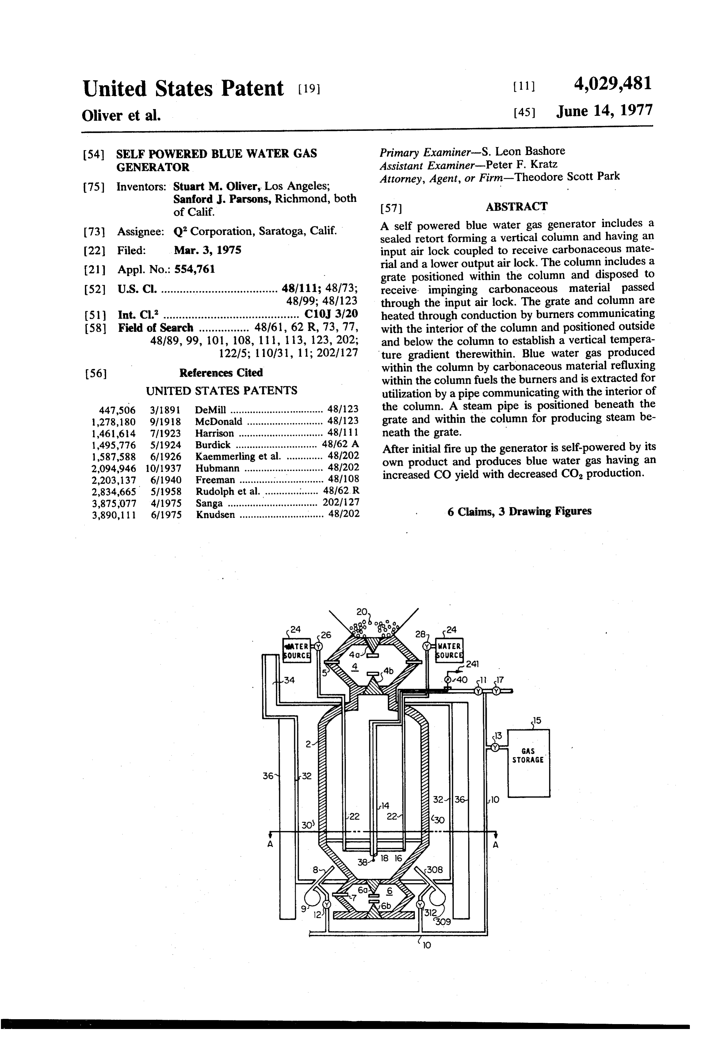
United States Patent (19) (11) 4,029,481 Oliver et al. (45) June 14, 1977 54 SELF POWERED BLUE WATER GAS Primary Examiner-S. Leon Bashore GENERATOR Assistant Examiner-Peter F. Kratz (75) Inventors: Stuart M. Oliver, Los Angeles; Attorney, Agent, or Firm-Theodore Scott Park Sanford J. Parsons, Richmond, both of Calif. 57 ABSTRACT (73) Assignee: Q Corporation, Saratoga, Calif. A self powered blue water gas generator includes a w sealed retort forming a vertical column and having an 22 Filed: Mar. 3, 1975 input air lock coupled to receive carbonaceous mate (21) Appl. No.: 554,761 rial and a lower output air lock. The column includes a grate positioned within the column and disposed to (52) U.S. C. ..................................... 48/111; 48/73; receive impinging carbonaceous material passed 2 48/99; 48/123 through the input air lock. The grate and column are 51 Int, Cl- ........................................... C10J 3/20 heated through conduction by burners communicating 58 Field of Search ................ “8161.92R, 73,77, with the interior of the column and positioned outside 48189,99, 101, 108, 111, 1 13, 123, 202; and below the column to establish a vertical tempera 1225; 110731, 11; 202/127 ture gradient therewithin. Blue water gas produced 56 References Cited within the column by carbonaceous material refluxing within the column fuels the burners and is extracted for
UNITED STATES PATENTS utilization by a pipe communicating with the interior of 447,506 3/1891 DeMill ................................. 48/123 the column. A steam pipe is positioned beneath the 1,278,180 9/1918 McDonald ................... ... 48/123 grate and within the column for producing steam be 1461,614 7/1923 Harrison .............................. 4811 11 neath the grate.
1,495,776 5/1924 Burdick ............................. 48/62 A 1,587,588 6/1926 Kaemmerling et al... ... 48/202 After initial fire up the generator is self-powered by its 2,094,946 10/1937 Hubmann ................. ... af202 own product and produces blue water gas having an 2,203,137. 6/1940 Freeman ........ ... 48/108 increased CO yield with decreased CO production. 2,834,665 5/1958 Rudolph et al... . . 48762. R 3,875,077 4/1975 Sanga ................................ 202/127 3,890, l l l 6/1975 Knudsen .............................. 48/202 6 Claims, 3 Drawing Figures
water 2NS2
Page 2
Drawing sheet — no readable text.
Page 3
Drawing sheet — no readable text.
Page 4
Drawing sheet — no readable text.
Page 5
forming a vertical column 2. Reflux chamber 2 has a
SELF POWERED BLUE WATER GAS GENERATOR raw material inlet air lock 4 and an outlet ash air lock 6 and is constructed of firebox steel such as A.S.T.M.
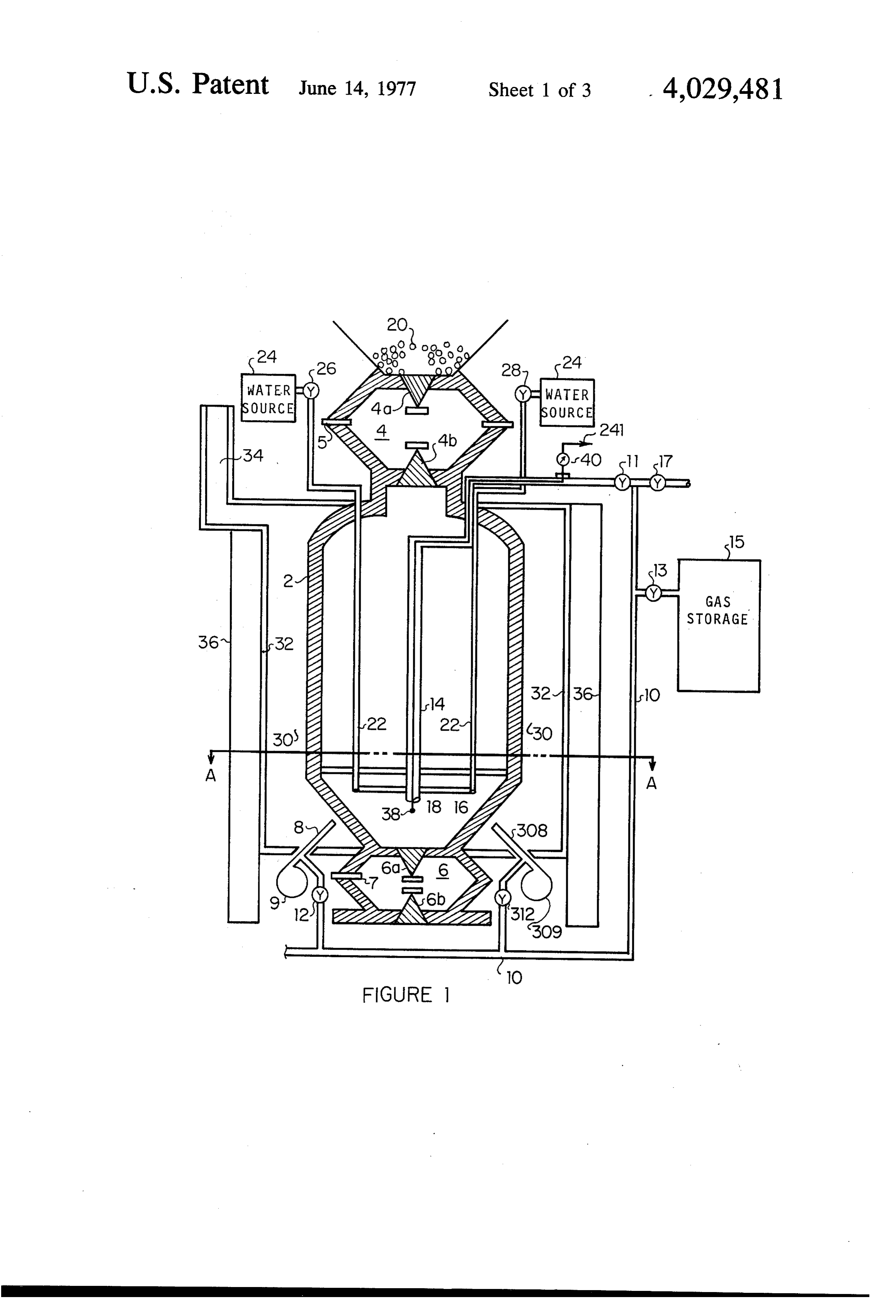
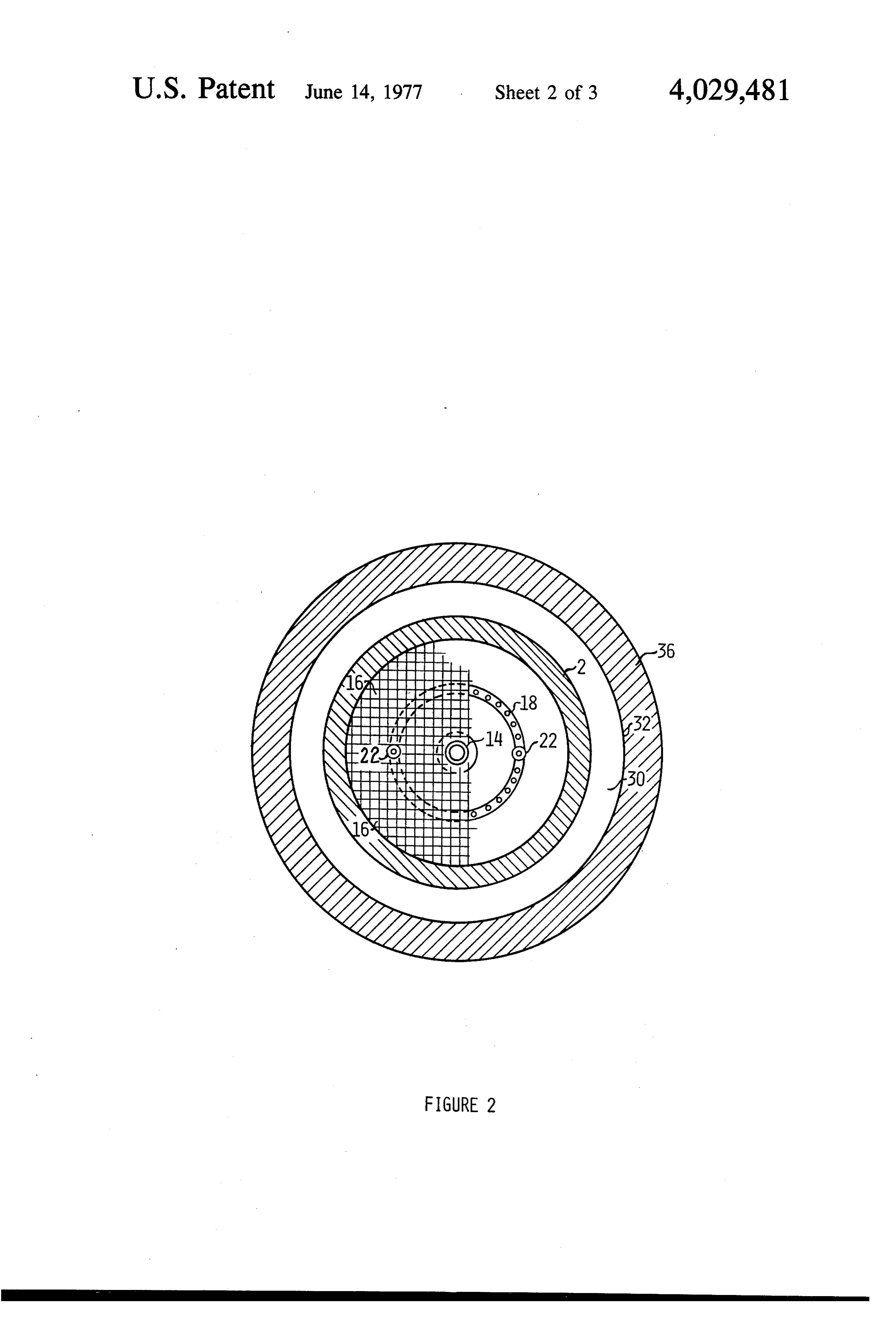
BACKGROUND AND SUMMARY 285-C or the like. Inlet air lock 4 and ash air lock 6 are The field of art to which the invention pertains is the each provided with vacuum extractors 5 and 7, respec gas generating art. Water gas generators are typically tively. Vacuum extractors 5 and 7 are coupled to a powered by a fuel or by materials containing thermal vacuum pump and activated in response to the air lock energy such as steam, heated coal or hot gasses. Inter they are positioned within being opened for extracting nal combustion processes requiring oxygen feeding are poisonous gasses which may otherwise escape from employed wherein a fuel such as, for example, coal or 10 reflux chamber 2 and for preventing any influx of oxy the like is burned within a forced air fed retort. Such gen. If, for example, carbonaceous material is to be fed processes produce undesirable amounts of carbon di through air lock 4, air lock 4 is evacuated by vacuum oxide for many catalytic processes requiring water gas. extractor 5 to extract any carbon monoxide, valve 4a is In addition, most prior generators are batch fed genera opened to receive carbonaceous material 20 within the tors and are incapable of continuous feeding and con 5 air lock and valve 4a is again closed. Air lock 4 is again tinuous emptying without interrupting gas generation. evacuated by vacuum extractor 5 to ensure a minimum The invention is a self powered continuous feeding and oxygen gas intake and valve 4b is opened to pass the continuous emptying gas generator producing blue carbonaceous material to the interior of reflux cham water gas by refluxing carbonaceous waste materials. ber 2. Valve 4b is then closed and air lock 4 again An externally heated reflux chamber formed by a 20 evacuated. Airlock 6 and valves 6a and 6b are similarly sealed retort forming a vertical column is heated to a operated to ensure minimum oxygen leakage into re temperature of approximately 1200° C and carbona flux chamber 2 and minimum carbon monoxide leak ceous materials are placed within the chamber. A por age out of reflux chamber 2. The gasses extracted are tion of the carbonaceous material vaporizes and the coupled by pipes and vacuum pumps (not depicted in remainder is oxidized into carbon monoxide. Sufficient 25 FIG. 1) to burners 8 and 308. The extractors also assist water is injected as steam beneath the heated grate inlet air lock 4 in receiving carbonaceous material and zone to provide sufficient hydrogen and oxygen to ash air lock 6 in passing ash produced by the generator. bring the reaction to completion. Remaining carbona The lower portion of the reflux chamber 2 is coni ceous materials and gasses reflux and impinge the cally shaped and thermally coupled to burners 8 and heated grate zone where the reaction conditions pro 30 308 positioned to direct heat to the cone as straight as duce carbon monoxide and hydrogen as the predomi possible to produce maximum heating of reflux cham nant species. More complex compounds are reduced to ber 2. The cone shaped lower portion of the reflux this state via a plurality of heating and reflux cycles. chamber 2 provides thermal reradiation within the Oxygen separates from hydrogen of the steam mole reflux chamber 2. Burner pipe 10 and valves 12 and cules and combines with the carbon when the hot car 35 312 couple the burners 8 and 308 which are blower bonaceous material is impinged by the steam thereby aspirated burners with attached air blowers 9 and 309 producing carbon monoxide and hydrogen gas. A por or the like to a water gas extractor pipe 14 positioned tion of the water gas so produced is utilized to maintain within reflux chamber 2. The water gas extractor pipe the operating temperature of the reflux chamber by 14 extends below a reflux grate 16 and steam ring 18. being burned outside of the reflux chamber and the 40 Reflux grate 16 and steam ring 18 are each positioned remaining water gas is available for utilization for heat within and thermally and structurally coupled to reflux ing, lighting, or catalysis to other compounds. There is chamber 2. The reflux grate 16 is positioned to receive no requirement to oxygen feed the reflux chamber carbonaceous material 20 which passes through input since required heat is provided by burning the gas pro valve 4 and falls through the column formed by reflux duced outside the reflux chamber and because a reflux 45 chamber 2. Steam ring 18 is positioned below the grate process is utilized instead of internally combusting the 16 and is connected to water pipes 22 which provide carbonaceous material. O, input is undesirable due to water from an external water source 24 via valves 26 the C0 produced thereby. Carbon monoxide and hy and 28. Referring to FIG. 2, a burner exhaust chamber drogen gas yield is enhanced with respect to carbon 30 is formed by a shell 32 formed of A.S.T.M. A285C dioxide production as a result. In addition, total gas 50 steel which surrounds reflux chamber 2. Exhaust cham yield is improved from approximately 40% in the prior ber 30 captures combustion gasses produced by burn art to 95% with the invention. Dangerous carbon mon ers 8 and 308 and directs them to exhaust stack 34. oxide gas produced by the generator is either contained Exhaust chamber 30 and shell 32 are surrounded by within the sealed reflux chamber, utilized, or burned. thermal insulation layers 36.
DESCRIPTION OF THE DRAWING
55 Reflux chamber 2 and grate 16 are elevated to a temperature of approximately 1190 C by externally
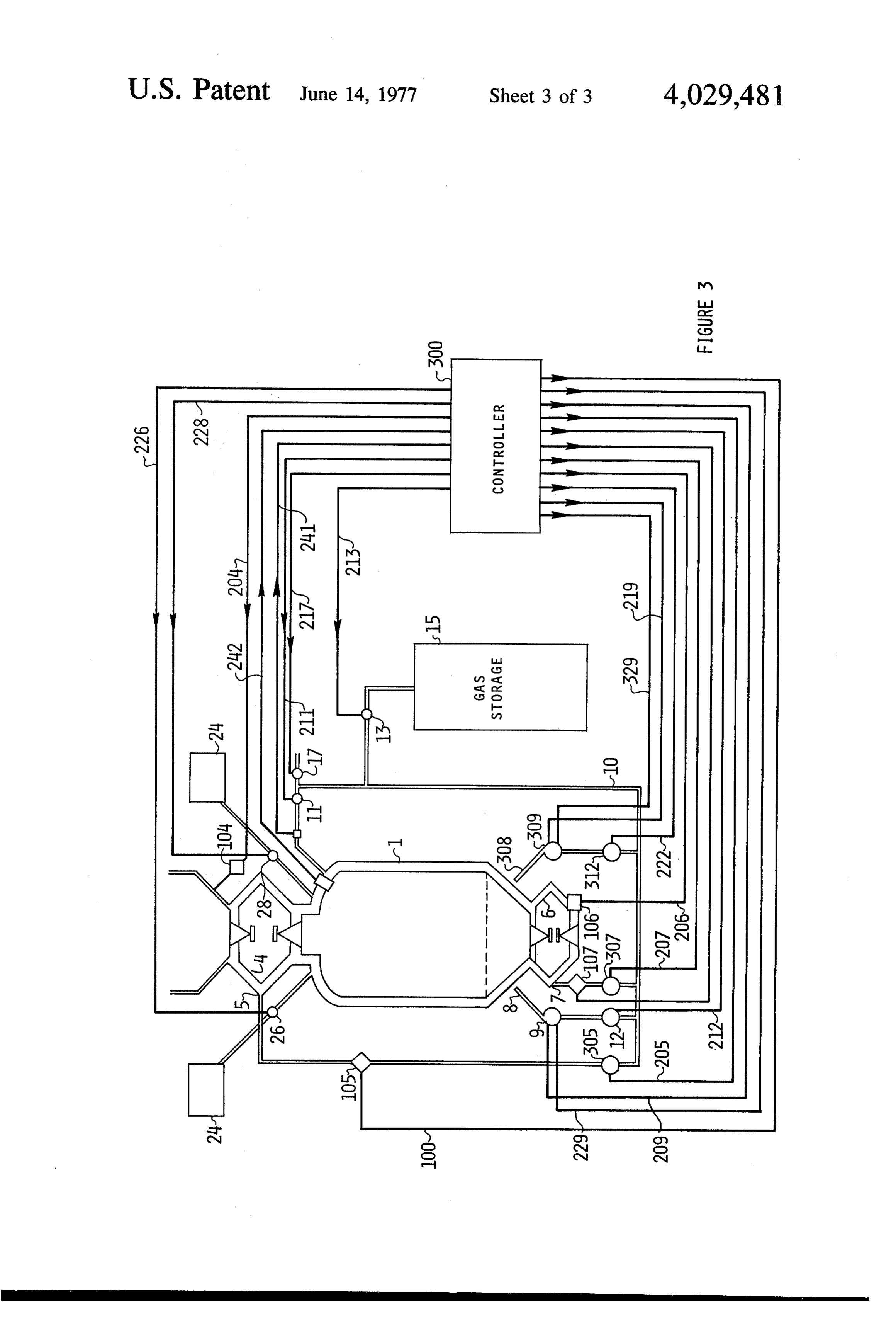
FIG. 1 is a sectional diagram of a self powered blue heating reflux chamber 2 by combusting previously water gas generator made in accordance with the in stored gas in gas storage 15 with burners 8 and 308. vention. Valves 11 and 17 are closed and valves 12 and 13 FIG. 2 is a sectional elevated view of the embodiment 60 opened and thermal energy produced is directed to the depicted in FIG. 1. reflux chamber 2 to initially put the generator into FIG. 3 is a schematic diagram of a control system for operation. The preferred embodiment requires four the generator of FIG. 1. burners to initially get reflux chamber 2 up to tempera DESCRIPTION OF THE PREFERRED ture and only one burner 8 is required to maintain the 65 temperature during subsequent operation. Preferably,
EMBODIMENT
carbonaceous waste 20 is introduced through valve 4
Referring to FIGS. 1 and 2, a gas generator is shown after reflux chamber 2 and grate 16 have reached the having a reflux chamber comprising a sealed retort operating temperature. Water is supplied from water
Page 6
source 24 in measured amounts as regulated by valves extractor 5 and vacuum pump 105 is passed by a valve 26 and 28 to pipes 22 which supply steam ring 18. The 305 controlled by signal 205 to pipes supplying fuel to water becomes steam during its passage through pipes the burners. Similarly, during ash removal, air lock 6 is 22 which are at a temperature well above the boiling opened in response to signals 206 from controller 300 point of water at the pressure existing within reflux by valve actuating means 106. A controllable vacuum chamber 2. The proper amount of water to add during pump 107 sucks gasses from vacuum extractor 7 and operation is determined empirically and is dependent supplies them via valve 307 to the burners 8 and 308. upon the type of carbonaceous waste utilized and its Four burners (only two are shown in FIG. 3) are water content. If the carbonaceous waste is, for exam preferably used to bring the generator up to a desired ple, wood chips cut to approximately .2-inch cubes in 10 temperature as discussed previously. The operating size, the preferred amount is an equal weight amount of temperature is sensed by a thermocouple 38, shown in water for a given weight of wood chips. The observed . FIG. 1 which transmits a signal 241 corresponding to ash resulting from this empirically derived amount is the temperature within reflux chamber 2. Controller approximately 5% by weight of the input wood chips. 300 adjusts the heat applied to the generator 1 by con Almost any carbonaceous material such as, for exam 15 trolling the amount of fuel to each burner, the air sup ple, chipped plastics, filter carbon waste from dry plied to each burner, and the number of burners in cleaning industry, fruit pits, or the like is suitable car operation. The amount of fuel is varied by valves 12 bonaceous material for the generator and the optimal and 312 which are controlled by signals 212 and 222, amount of water to be added is easily determined em respectively. The air supply to each burner is regulated pirically. 20 by regulating the speed of blowers 9 and 309 with sig Referring to FIG. 1, control valve 11 is opened in nals 209 and 219, respectively. The number of burners response to gas generation within reflux chamber 2 as in operation are controlled for example by shutting off indicated by for example, a pressure gauge. Storage gas the fuel and air supply to a particular burner. A se in gas storage 15 is replenished and valve 13 is closed. lected burner is brought into operation by supplying Water gas produced within reflux chamber 2 fuels 25 fuel to it and actuating an associated igniter. Each burners 8 and 308 to self power the generator and burner includes a controlled igniter, burner 8 having an excess water gas produced is available for utilization by igniter controlled by signal 229 and burner 308 having adjusting valve 17 to supply an external process or an igniter controlled by signal 329.
storage. Burners 8 and 308 and blowers 9 and 309 are Measured amounts of water from source 24 are adjusted to maintain the temperature at the end of gas 30 added by control valves 26 and 28 which are responsive extractor pipe 14 at 1190 C as detected by thermo to signals 226 and 228, respectively.
couple 38 and indicated by meter 40. The flow of gas produced is routed to storage tank Continuous operation through continuous feeding 15, an external load or the burners by valves 11, 17, and ash removal is possible due to air locks 4 and 6 and and 13 which are responsive to signals 211, 217, and the indirect heating reflux process. It is not necessary to 35 213, respectively.
shut down the generator to place additional carbona We claim:
ceous waste therein as air lock 4 maintains a substantial 1. A blue water gas generator comprising: seal during feeding and air lock 6 maintains a substan a sealed retort forming a vertical column and having tial seal during ash removal. Burners 8 and 308 and 40 an upper cylindrical portion and a lower inverse blowers 9 and 309 are maintained or replaced without conically shaped portion, the upper and lower por interrupting gas generation since they are positioned tions being separated by a grate which is thermally outside of reflux chamber 2 and are easily accessed coupled to the retort and disposed within the retort without need for unsealing reflux chamber 2. If one in a substantially horizontal plane; burner needs to be replaced another burner is capable means coupled to the sealed retort for applying steam of maintaining the operating temperature during a re 45 within the lower portion of the sealed retort; placement operation. burner means thermally coupled to the sealed retort The embodiment depicted in FIG. 1 has a reflux and disposed outside of the sealed retort and below chamber 2 having a height of 6 feet. Carbonaceous the grate for heating under reflux materials placed material such as wood chips sufficiently disperse by within the sealed retort and establishing a substan falling and refluxing within the chamber during feeding 50 tially vertical thermal gradient therein, the gradient and operation. Other input carbonaceous fuel may having a higher temperature potential at the lower require the inclusion of baffles or the like to ensure portion of the retort than at the upper portion; sufficient dispersion over grate 16. Grate 16 can also be an input air lock coupled to the upper portion of the made moveable and include shaking apparatus at retort and operatively disposed above the grate to tached thereto. 55 receive carbonaceous materials and pass them onto Referring to FIG. 3, there is shown a control system the grate;
for generator 1. Input air lock 4 is opened in response an output air lock coupled to the lower portion of the to control signals 204 from controller 300. Controller sealed retort and operatively disposed below the 300 is a manually operated console, a specially pro grate to receive material which passes through the grammed computer or the like. Control signals 204 60 grate; and actuate valve actuating means 104. Means 104 is an gas extraction means coupled to the retort and com electrical solenoid operating fulcrums coupled to municating with the lower portion of the retort for spring loaded valves, or the like. A controllable vac receiving gas produced in the retort and being uum pump 105 coupled to vacuum extractor 5 is actu coupled to the burner means to burn a portion of ated in response to a signal 100 from controller 300. 65 the gas product.
The rate, timing, and duration of vacuum is controlled 2. A gas generator as in claim comprising means and correlated with actuation of the valves of inlet air thermally coupled to the sealed retort and coupled to lock 4 by controller 300. Gas extracted by vacuum the means for heating for regulating the temperature of
Page 7
the lower portion of the sealed retort about a selected 4. A gas generator as in claim 3 comprising means temperature range. coupled to the first vacuum extraction means for com busting gas extracted from the receiving valve means.
3. A gas generator as in claim 1 wherein the input air 5. A gas generator as in claim 4 comprising means lock comprises: coupled to the second vacuum extraction means for combusting gas extracted from the output valve means.
receiving valve means coupled to the sealed retort for 6. A gas generator as in claim 1 wherein the output receiving carbonaceous material and passing the air lock comprises:
carbonaceous material to the interior of the retort 10 output valve means coupled to the sealed retort for receiving ash produced by the gas generator and and for maintaining a substantial seal during said for maintaining a substantial seal during said re receiving and passing; and ceiving; and first vacuum extraction means coupled to the receiv second vacuum extraction means coupled to the output valve means.
Provenance
- Collection
- Cited prior art
- Original PDF
- patentimages.storage.googleapis.com →
- Filed
- 1975-03-03
- Pages
- 7
- Method
- pdftotext (the PDF's own text layer) + pdftoppm 300dpi page scans
- Source
- Google Patents bibliographic record
- Granted
- 1977-06-14
- Inventors
- Stuart M. Oliver; Sanford J. Parsons; Q2 Corp
- Transcribed from
- patentimages.storage.googleapis.com →