patent · US4586076
Scanner optics for containing scattered light
29 April 1986
Page 1 — bibliographic record
United States Patent (19) 11 Patent Number: 4,586,076 Watt 45) Date of Patent: Apr. 29, 1986 54 SCANNER OPTICS FOR CONTAINING 4,225,782 9/1980 Kuppenheimer, Jr. et al. ... 250/216 SCATTERED LIGHT 4,481,414 11/1984 Gasper ................................ 250/226
FOREIGN PATENT DOCUMENTS
75 Inventor: Peter B. Watt, Welwyn, England 73) Assignee: Eastman Kodak Company, 1013423 12/1965 United Kingdom .................. 358/75 Rochester, N.Y. 1273360 5/1972 United Kingdom.
21 Appl. No.: 556,235 OTHER PUBLICATIONS 22, PCT Filed: Feb. 9, 1983 Morse, D. R., “A Review of Telecine Systems,” Journal 86 PCT No.: PCT/GB83/00037 of the SMPTE, vol. 73, Jul. 1964, pp. 548-560. S371 Date: Sep. 26, 1983 Seddon, R. E., "Interference Filters for Colormetric Applications," Proc. of the Suc. of Photo-Optical Instru
S 102(e) Date: Sep. 26, 1983 mentation Engineers, vol. 50 (Optical Coatings), Aug. 87 PCT Pub. No.: WO83/02869 1974, pp. 153-162.
PCT Pub. Date: Aug. 18, 1983 Primary Examiner-James J. Groody
Assistant Examiner-Randall S. Svihla (30) Foreign Application Priority Data Attorney, Agent, or Firm-David M. Woods Feb. 12, 1982 GB United Kingdom................. 8204083 57 ABSTRACT 51) Int. Cl." ........................ H04N 1/46; H04N 9/04; An optical scanner (10) scans a color transparency (11) H04N 5/257; H04N 1/028 with a spot of light from a scanning beam. The light 52 U.S.C. ........................................ 358/75; 358/41; transmitted by the transparency, which is modulated 358/50; 358/55; 358/209; 358/225; 358/294; according to the color content and density of the trans 250/578 parency, enters a beam splitter (21, 28) for separation 58 Field of Search ............... 313/524, 532, 542, 543, into spectrally-different components. Each component 313/544; 250/237 R, 578; 350/172, 173,314, is passed to a photoresponsive detecting device (12, 13, 397, 398, 408; 358/41, 50, 52, 54, 55, 209, 211, 14). To compensate for scratches and dirt on the trans 214, 215, 216, 225, 285,293,294, 75, 76, 78, 80 parency, which scatter the transmitted light away from (56) References Cited the beam splitter, an internally reflective mirror box (30,
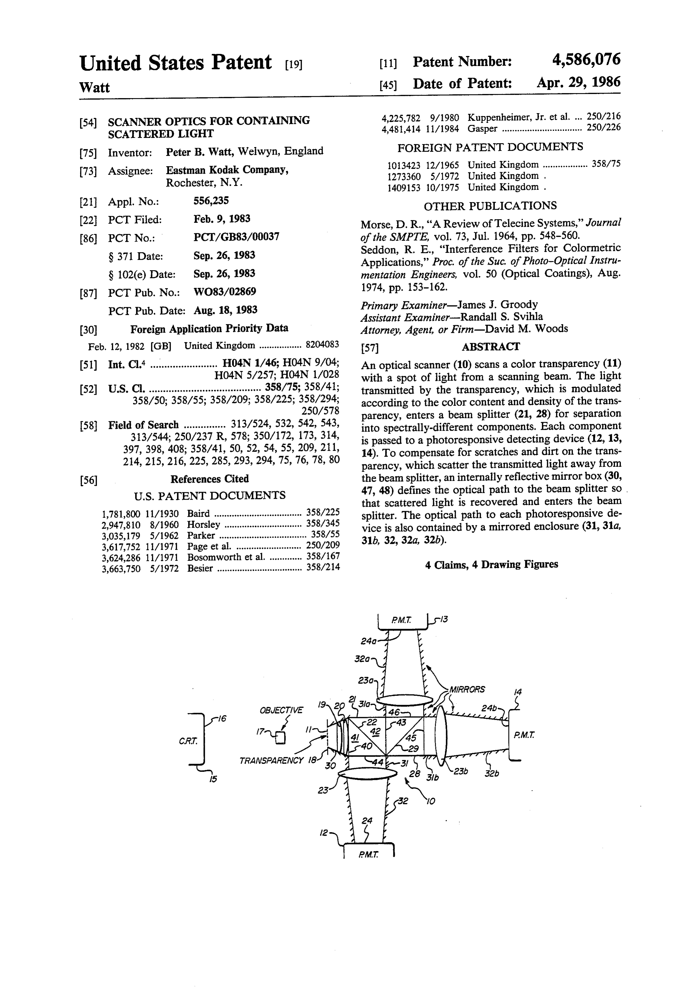
that scattered light is recovered and enters the beam 1,781,800 1 1/1930 Baird ................................... 358/225 splitter. The optical path to each photoresponsive de 2,947,810 8/1960 Horsley ............................... 358/345 vice is also contained by a mirrored enclosure (31, 31a, 3,035,179 5/1962 Parker ................................... 358/55 31b, 32, 32a, 32b).
3,624,286 11/1971 Bosomworth et al. . ... 358/167 3,663,750 5/1972 Besier .................................. 358/214 4 Claims, 4 Drawing Figures
CRT.
Page 2
Drawing sheet — no readable text.
Page 3
Drawing sheet — no readable text.
Page 4
with a spot of light from a scanning beam, a beam split
SCANNER OPTICS FOR CONTAINING ter located so as to receive light transmitted by the SCATTERED LIGHT transparency, a photomultiplier or like photoresponsive device located in spaced relationship to each exit of the
This invention concerns scanners of the kind where 5 beam splitter, and internally reflective optical path de an original information bearing record such as a photo fining means between the gate and the entrance of the graphic negative or positive is scanned in a point to beam splitter.
point manner by a spot of light and the spot of light is The optical path defining means may comprise inter modulated by the information carried by the record. nally reflective mirror boxes and/or lenses for contain The modulated spot of light is passed to a photomulti 10 ing and directing modulated light from the transpar plier or like photosensitive device and an electrical ency or other information bearing record to the en signal is generated which corresponds to the instanta trance of the beam splitter. There may be similar optical neous information carried by the original at that point. path defining means from the exits of the beam splitter Such an apparatus may form part of a telecine appara to the detecting surfaces of the photomultipliers or like tus, a photographic printer, a facsimile transmitter or a 15 photoresponsive devices.
document copier. The beam splitter is preferably of cubic form and of a One method of scanning in a point to point manner is material of high refractive index such as glass. to utilise a cathode ray tube and to provide a raster on The invention will be described further, by way of the face thereof. The raster is imaged on the original example, with reference to the accompanying drawings, information bearing record and the transmitted modu 20 in which:
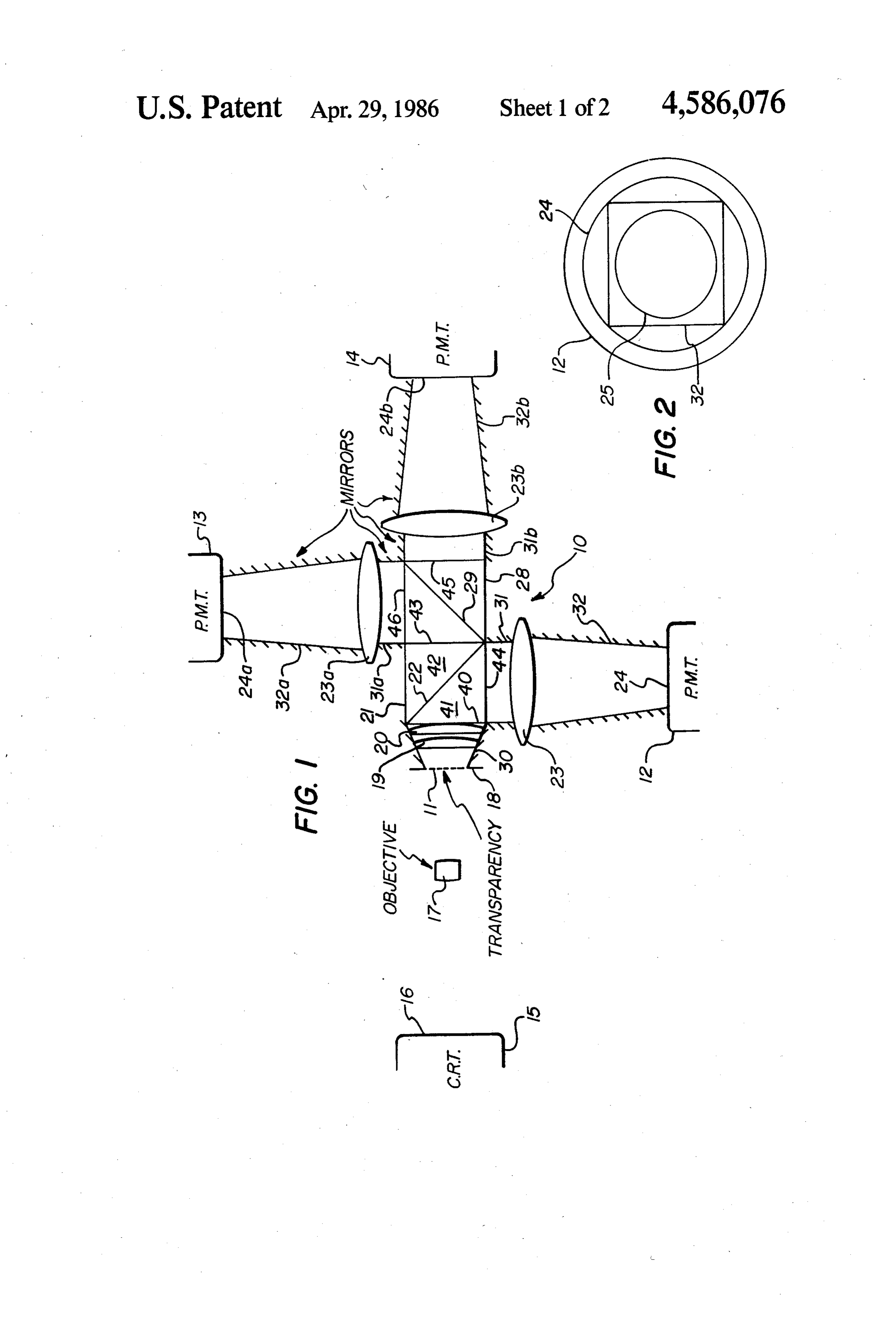
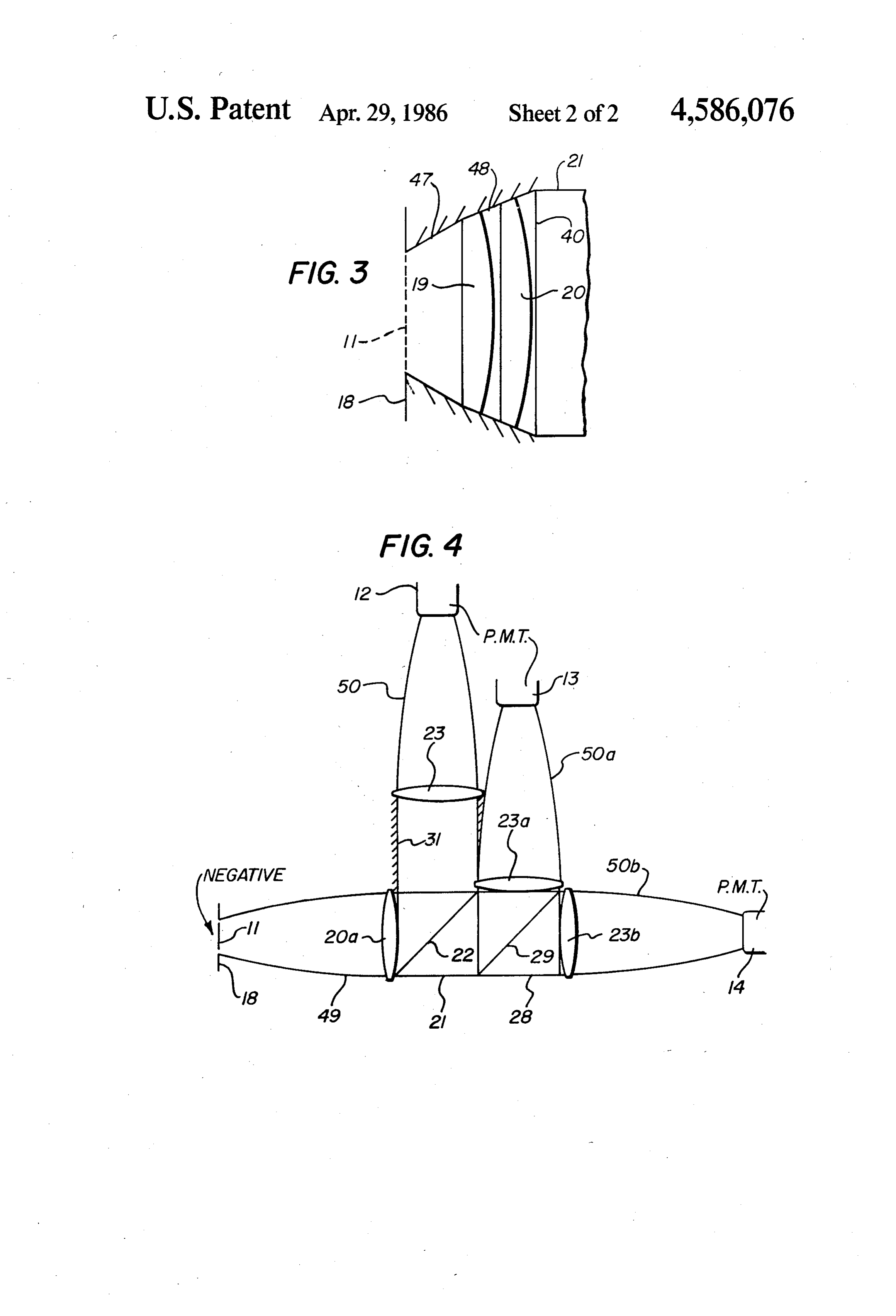
lated light, if the original is transparent such as a photo FIG. 1 is a diagrammatic view of a colour scanner graphic negative or positive, is detected. It is known, incorporating a beam splitter and optical path defining however, to utilise a point light source and appropriate means in accordance with the present invention; optical components to obtain point to point scanning. FIG. 2 is a diagrammatic view of the detecting sur In the case of a transparency, specularly transmitted 25 face of a photomultiplier or like photoresponsive device light causes few problems and a simple optical path, useful in a scanner having a beam splitter and optical which may include beam splitters, to one or more pho path defining means according to the present invention; tomultipliers or like photo-responsive devices, can be and used. FIGS. 3 and 4 show alternative forms of light collect One problem that arises in scanners is if the original is 30 ing and directing means useful in a scanner having a dirty or scratched, the light transmitted thereby, if a beam splitter and optical path defining means according transparency, is scattered and a proportion is not nor to the present invention.
mally received by the photomultiplier or like photore As shown in FIGS. 1 and 2 of the drawings, a colour sponsive device. The output signal of the photomulti film scanner 10 is arranged to scan a colour transpar plier indicates a high density at such a point on the 35 ency 11 (positive or negative) with a beam of light and original and, in a photographic printer where the origi to provide point to point image information as to the nal is a photographic negative, the reproduction shows colour content and density of the transparency, in the a scratch as a white line and a speck of dirt as a white form of electrical signals at the outputs of three photo spot. A corresponding readily visible defect appears on multipliers 12, 13 and 14.
the television screen of a telecine apparatus. The scanner comprises a cathode ray tube 15 and An electronic partial solution to this problem in tele conventional electrical circuits (not shown) which pro cine apparatus is described in U.K. Patent Specification vide horizontal and vertical time bases to produce a No. 1,409,153, and another electronic partial solution to raster on the face 16 thereof of relative dimensions at this problem in an electronic motion picture printer is least corresponding to the dimensions of the transpar described in U.S. Pat. No. 2,947,810. 45 ency 11 to be scanned. An objective 17 images the raster The problem is made worse in colour scanners in that onto the transparency 11 located in a film gate 18. Light optical components are necessary to split the beam of transmitted by the transparency is collected by optical modulated light into, for example, three colour compo path defining means comprising a first truncated pyra nents, usually red, blue and green. This beam splitting midal mirror box 30 surrounding the gate 18, and lenses may be affected by partially silvered mirrors followed 50 19 and 20 direct the collected light onto the planar by appropriate colour filters and respective photomulti entrance face 40 of a transparent beam splitting cube 21. pliers or, more efficiently, by dichroic mirrors and re The cube 21 comprises two equal right angled prisms 41 spective photomultipliers both as described in U.S. Pat. and 42 of a relatively high refractive index material No. 2,947,810. In beam splitting, unless arrangements such as glass. The hypoteneusal surface of one of the are made to contain scattered light, further light losses 55 prisms 41 or 42 has a dichroic mirror 22 formed as an occur even when using dichroic mirrors. These losses interference coating thereon of thickness such as to are far greater for scattered light which does not im reflect red light incident thereon at approximately 45 pinge on the mirrors at or near the design angle, usually and to transmit green and blue light incident thereon at 45°. Whenever a scratch or speck of dirt on the original approximately 45. The prisms 41 and 42 are cemented is scanned, the output of the photomultiplier(s) or like together with Canada balsam or a like adhesive with the photo-responsive device(s) normally drops due to light hypoteneusal surfaces in contact along the surface de lost by scattering. fining the dichroic mirror 22. It is an object of the present invention to overcome The cube 21 has a first planar exit face 43 parallel to this problem in a simple optical manner. the entrance face wherethrough green and blue light In accordance with the present invention, there is 65 transmitted by the dichroic mirror exit the cube, and a provided a colour scanner comprising a gate whereat a second planar exit face 44 at right angles to the entrance transparency to be scanned may be located, means for face 40 wherethrough red light reflected by the di scanning the transparency in a point to point manner chroic mirror exits the cube. The second exit face is
Page 5
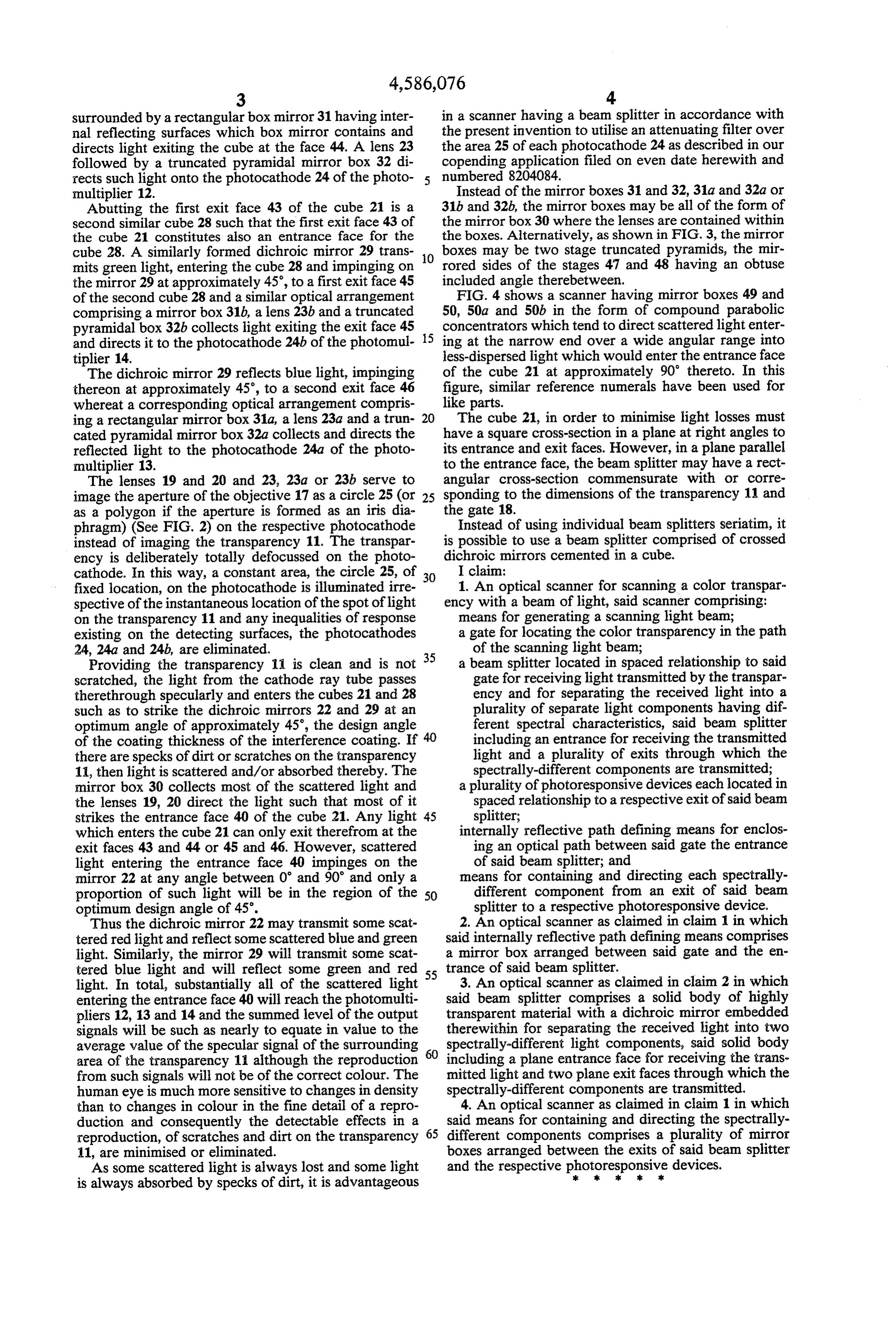
surrounded by a rectangular box mirror 31 having inter in a scanner having a beam splitter in accordance with nal reflecting surfaces which box mirror contains and the present invention to utilise an attenuating filter over directs light exiting the cube at the face 44. A lens 23 the area 25 of each photocathode 24 as described in our followed by a truncated pyramidal mirror box 32 di copending application filed on even date herewith and rects such light onto the photocathode 24 of the photo numbered 8204084.
multiplier 12. Instead of the mirror boxes 31 and 32, 31a and 32a or Abutting the first exit face 43 of the cube 21 is a 31b and 32b, the mirror boxes may be all of the form of second similar cube 28 such that the first exit face 43 of the mirror box 30 where the lenses are contained within the cube 21 constitutes also an entrance face for the the boxes. Alternatively, as shown in FIG. 3, the mirror cube 28. A similarly formed dichroic mirror 29 trans O boxes may be two stage truncated pyramids, the mir mits green light, entering the cube 28 and impinging on rored sides of the stages 47 and 48 having an obtuse the mirror 29 at approximately 45, to a first exit face 45 included angle therebetween.
of the second cube 28 and a similar optical arrangement FIG. 4 shows a scanner having mirror boxes 49 and comprising a mirror box 31b, a lens 23b and a truncated 50, 50a and 50b in the form of compound parabolic pyramidal box 32b collects light exiting the exit face 45 15 concentrators which tend to direct scattered light enter and directs it to the photocathode 24b of the photomul ing at the narrow end over a wide angular range into tiplier 14. less-dispersed light which would enter the entrance face The dichroic mirror 29 reflects blue light, impinging of the cube 21 at approximately 90' thereto. In this thereon at approximately 45°, to a second exit face 46 figure, similar reference numerals have been used for whereat a corresponding optical arrangement compris like parts.
ing a rectangular mirror box 31a, a lens 23a and a trun 20 The cube 21, in order to minimise light losses must cated pyramidal mirror box 32a collects and directs the have a square cross-section in a plane at right angles to reflected light to the photocathode 24a of the photo its entrance and exit faces. However, in a plane parallel multiplier 13. to the entrance face, the beam splitter may have a rect The lenses 19 and 20 and 23, 23a or 23b serve to angular cross-section commensurate with or corre image the aperture of the objective 17 as a circle 25 (or 25 sponding to the dimensions of the transparency 11 and as a polygon if the aperture is formed as an iris dia the gate 18.
phragm) (See FIG. 2) on the respective photocathode Instead of using individual beam splitters seriatim, it instead of imaging the transparency 11. The transpar is possible to use a beam splitter comprised of crossed ency is deliberately totally defocussed on the photo dichroic mirrors cemented in a cube.
cathode. In this way, a constant area, the circle 25, of 30 I claim:
fixed location, on the photocathode is illuminated irre 1. An optical scanner for scanning a color transpar spective of the instantaneous location of the spot of light ency with a beam of light, said scanner comprising: on the transparency 11 and any inequalities of response means for generating a scanning light beam; existing on the detecting surfaces, the photocathodes a gate for locating the color transparency in the path 24, 24a and 24b, are eliminated. of the scanning light beam; Providing the transparency 11 is clean and is not 35 a beam splitter located in spaced relationship to said scratched, the light from the cathode ray tube passes gate for receiving light transmitted by the transpar therethrough specularly and enters the cubes 21 and 28 ency and for separating the received light into a such as to strike the dichroic mirrors 22 and 29 at an plurality of separate light components having dif optimum angle of approximately 45, the design angle ferent spectral characteristics, said beam splitter of the coating thickness of the interference coating. If 40 including an entrance for receiving the transmitted there are specks of dirt or scratches on the transparency light and a plurality of exits through which the 11, then light is scattered and/or absorbed thereby. The spectrally-different components are transmitted; mirror box 30 collects most of the scattered light and a plurality of photoresponsive devices each located in the lenses 19, 20 direct the light such that most of it spaced relationship to a respective exit of said beam strikes the entrance face 40 of the cube 21. Any light 45 splitter;
which enters the cube 21 can only exit therefrom at the internally reflective path defining means for enclos exit faces 43 and 44 or 45 and 46. However, scattered ing an optical path between said gate the entrance light entering the entrance face 40 impinges on the of said beam splitter; and mirror 22 at any angle between 0 and 90' and only a means for containing and directing each spectrally proportion of such light will be in the region of the 50 different component from an exit of said beam optimum design angle of 45. splitter to a respective photoresponsive device. Thus the dichroic mirror 22 may transmit some scat 2. An optical scanner as claimed in claim 1 in which tered red light and reflect some scattered blue and green said internally reflective path defining means comprises light. Similarly, the mirror 29 will transmit some scat a mirror box arranged between said gate and the en tered blue light and will reflect some green and red 55 trance of said beam splitter.
light. In total, substantially all of the scattered light 3. An optical scanner as claimed in claim 2 in which entering the entrance face 40 will reach the photomulti said beam splitter comprises a solid body of highly pliers 12, 13 and 14 and the summed level of the output transparent material with a dichroic mirror embedded signals will be such as nearly to equate in value to the therewithin for separating the received light into two average value of the specular signal of the surrounding 60 spectrally-different light components, said solid body area of the transparency 1 although the reproduction including a plane entrance face for receiving the trans from such signals will not be of the correct colour. The mitted light and two plane exit faces through which the human eye is much more sensitive to changes in density spectrally-different components are transmitted. than to changes in colour in the fine detail of a repro 4. An optical scanner as claimed in claim 1 in which duction and consequently the detectable effects in a 65 said means for containing and directing the spectrally reproduction, of scratches and dirt on the transparency different components comprises a plurality of mirror 11, are minimised or eliminated. boxes arranged between the exits of said beam splitter As some scattered light is always lost and some light and the respective photoresponsive
devices.
is always absorbed by specks of dirt, it is advantageous
Page 6
UNITED STATES PATENT OFFICE
CERTIFICATE OF CORRECTION
INVENTOR(S) : Peter B. Watt
It is certified that error appears in the above-identified patent and that said Letters Patent are hereby Corrected as shown below:
Column 4, line 47, after the word "gate" insert ---and---.
eigned and Sealed this
Nineteenth Day of August 1986
SEAL)
Attest
DONALDJ. QUGG
Attesting Officer Commissioner of sents and Tradewarks
Provenance
- Collection
- Cited prior art
- Original PDF
- patentimages.storage.googleapis.com →
- Filed
- 1983-02-09
- Pages
- 6
- Method
- pdftotext (the PDF's own text layer) + pdftoppm 300dpi page scans
- Source
- Google Patents bibliographic record
- Granted
- 1986-04-29
- Inventors
- Peter B. Watt; Eastman Kodak Co
- Transcribed from
- patentimages.storage.googleapis.com →