patent · US5884475
Method and device for introducing liquid into an exhaust-gas purification system
23 March 1999
Page 1 — bibliographic record
United States Patent (19) 11 Patent Number: 5,884,475 Hofmann et al. (45) Date of Patent: Mar 23, 1999 54 METHOD AND DEVICE FOR INTRODUCING 4,982.565 1/1991 Projahn ..................................... 60/303 LIQUID INTO AN EXHAUST-GAS 4,991,396 2/1991 Goerlich et al. ... 60/303 PURIFICATION SYSTEM 5,522,218 6/1996 Lane et al. ................................ 60/274 75 Inventors: Lothar Hofmann, Burgkunstadt; Primary Examiner Thomas E. Denion Ronald Neufert; Wieland Mathes, Attorney, Agent, or Firm-Herbert L. Lerner; Laurence A. both of Michelau, all of Germany Greenberg
73 Assignee: Siemens Aktiengesellschaft, Munich, 57
Germany Nitrogen oxides emitted by an internal-combustion engine operated with exceSS air are normally converted by the 21 Appl. No.: 816,365 method of selective catalytic reduction by bringing the nitrogen oxides, together with ammonia, into contact with a 22 Filed: Mar 13, 1997 Selective catalyst. Due to the dangers associated with the use O O of ammonia, in a motor vehicle ammonia should only be
Related U.S. Application Data carried in the form of a Substance which liberates ammonia, generally an aqueous urea Solution. A method and a device 63 Continuation of PCT/DE95/O1248, Sep. 12, 1995. for introducing liquid into an exhaust-gas purification Sys 30 Foreign Application Priority Data tem according to the invention avoids frost damage to Sections of the System during shutdown times and permits
Sep. 13, 1994 DE Germany .......................... 44 32577.O operation of the System at temperatures below the freezing Sep. 13, 1994 DE Germany .......................... 44 32576.2 point of the reducing agent Solution being used. The method (51) Int. Cl. .................................................. F01N3/00 and device include a (thermally insulated) reservoir for the 52 U.S. Cl. ................................. 60,274; 60/206; 60/301; reducing agent liquid and a liquid Supply line, which is 60/303 connected thereto and terminates in an outlet opening for the 58 Field of Search .............................. 60/302, 299, 301,
liquid. The reservoir and the liquid supply line can be heated. Furthermore, a heater is provided for liquefying a s s Starting Volume which is Small as compared with the Volume 56) References Cited of the reservoir. The liquid supply line may also have a back-flush Valve to which a gas that is under pressure can be
4.522,082 6/1985 Hasegawa et al. ....................... 60/286 4,615,173 10/1986 Usui et al. ................................ 60/286 27 Claims, 3 Drawing Sheets
s y: s his 18 risk- 24 in-22
"O – ... ii. -
X------contao - - - - - - - - - - - -- x
== s f 33 s / - His basis first 4. 2 ". S. 12 4 23. N 42
Page 2
Drawing sheet — no readable text.
Page 3
Drawing sheet — no readable text.
Page 4
Drawing sheet — no readable text.
Page 5
METHOD AND DEVICE FOR INTRODUCING Solution by hydrolysis in the exact quantity instantaneously LIQUID INTO AN EXHAUST-GAS required to convert the nitrogen oxides. PURIFICATION SYSTEM It is an advantage of the Substances, Such as urea, for example, which are present in aqueous Solutions and liberate
CROSS-REFERENCE TO RELATED ammonia, that the Storing, manipulation, conveyability and APPLICATION meterability are particularly easy to Solve technically. A This application is a Continuation of International Appli Serious disadvantage of those aqueous Solutions is that there cation Serial No. PCT/DE95/01248, filed Sep. 12, 1995. is a danger of freezing at certain temperatures as a function of the concentration of the dissolved Substance.
BACKGROUND OF THE INVENTION The simple addition of an antifreeze founders because no antifreeze is known for Such aqueous Solutions, which
Field of the Invention effects an appreciable lowering of the freezing point in The invention relates to a method for operating an economical doses. Moreover, if an additional Substance, exhaust-gas purification device in the exhaust of a combus 15 Such as an antifreeze, is used in that case, there is generally tion System, in particular in the exhaust of an internal the danger that, in conjunction with the use of a reducing combustion engine of a motor vehicle, into the exhaust gas agent in the exhaust-gas purification System, undesirable of which a liquid that is drawn from a reservoir through a byproducts are produced which are emitted along with the Supply line is introduced during the combustion, for chemi exhaust gas. For that reason, antifreezes cannot be used in cal purification of the exhaust gas. Such a method is dis Such a method for exhaust-gas purification. closed in Published European Patent Application 0.577 853 A further possibility for avoiding the freezing of the A1. aqueous Solution and for avoiding frost damage is in prin The invention also relates to a device for introducing a ciple to heat those parts of the exhaust-gas purification liquid into an exhaust-gas purification device, including a System which carry reducing agent. However, in the case of reservoir for the liquid and a Supply line, connected thereto, 25 mobile applications, especially utility motor vehicles for the exhaust-gas purification device. (trucks), locomotives and ships (insofar as they are not The invention is also Suitable for heating Systems and provided with an internal energy Supply), the electrical other Stationary combustion Systems, provided they make energy necessary for that purpose is not available, in par provision for the purification of the exhaust gas in Such a ticular during prolonged shutdown times. Thus, for example, way that a liquid (Such as, for example, urea Solution) is a volume of about 1001 of aqueous urea solution would have introduced into the exhaust gas in Sprayed or nebulized form to be protected against freezing in the case of a truck. or in another manner, as is provided, for example, in the SUMMARY OF THE INVENTION catalytic purification of Some industrial exhaust gases. In that connection, the introduction of the liquid may be a It is accordingly an object of the invention to provide a problem if, after a prolonged operating Stoppage, the tem 35 method and a device for introducing liquid into an exhaust perature has dropped So far that the liquid has an unduly high gas purification System in Such a way that frost damage to Viscosity or is completely frozen. However, the invention is the exhaust-gas purification System in which the liquid is primarily intended for internal-combustion engines in motor Sprayed into the exhaust gas is avoided during shutdown vehicles. times. As a result, the operation of Such a System is intended In order to reduce the pollutants contained in the exhaust 40 to
be possible even at temperatures below the freezing point the liquid being used.
gas of an internal-combustion engine, in particular the nitrogen oxides, the principle of the regulated or controlled With the foregoing and other objects in view there is Diesel catalytic converter (CDC) has proved advantageous. provided, in accordance with a first embodiment of the That procedure is used primarily in internal-combustion invention, a method for operating an exhaust-gas purifica engines which are operated with an exceSS of air, Such as, for 45 tion device, which comprises drawing a liquid from a example, Diesel engines and lean-running engines. The reservoir through a Supply line; introducing the liquid into procedure, which is based essentially on the method of an exhaust gas in an exhaust of a combustion System during Selective catalytic reduction (SCR) is disclosed in numerous combustion, for chemical purification of the exhaust gas, publications and patent applications, for example in German and draining at least a Section of the Supply line with a Published, Non-Prosecuted Patent Application DE 43 09 50 preSSurized gas during a shutdown of the combustion SyS 891 A1, corresponding to U.S. application Ser. No. 08/490, tem.
115, filed Jun. 12, 1995; German Published, Non-Prosecuted The Supply line therefore cannot freeze and be damaged Patent Application DE 43 10 926 A1; and German in the proceSS. It is available for a restart even at low Published, Non-Prosecuted Patent Application DE 43 15 temperatures.
278 A1, corresponding to U.S. application Ser. No. 08/551, 55 In accordance with another mode of the invention, there 791, filed Nov. 7, 1995. In the case of the SCR method, the is provided a valve which opens into the Supply line between nitrogen oxides, together with ammonia, are brought into the reservoir and the exhaust of the combustion System. contact with a Selective catalyst and catalytically converted Thus, it is easily possible, on one hand, to drain the part of into environmentally Safe nitrogen and water. the Supply line situated between the gas inlet and the Due to the danger associated with the use of ammonia, 60 reservoir into the reservoir by using the pressurized gas and, namely the toxicity, and because of the nasal nuisance on the other hand, to also drain the part of the Supply line caused by ammonia, ammonia should not be carried in the Situated between the gas inlet and the exhaust into the motor vehicle in the case of an internal-combustion engine exhaust by using the pressurized gas. equipped with a CDC System. Instead of ammonia, an With the objects of the invention in view, there is also aqueous urea Solution is carried in the motor vehicle as a 65 provided a Second embodiment of a method of operating an reducing agent for the catalytic conversion of the nitrogen exhaust-gas purification device, which comprises drawing a oxides. Ammonia is always produced from the aqueous urea liquid through a Supply line from a reservoir having a given
Page 6
Volume, introducing the liquid into an exhaust gas in an Surized air which is introduced into the liquid Supply line exhaust of a combustion System during combustion, for through the back-flush valve.
chemical purification of the exhaust gas, and heating a In accordance with yet another feature of the invention, Starting Volume of the liquid being Smaller than the given the path of the liquid supply line between the back-flush Volume with a heater and introducing the Starting Volume, Valve and the outlet opening is particularly short as com Such as from a container, into the exhaust gas, during or pared with the total length of the liquid Supply line. This is shortly before startup of the combustion system. advantageous, for example, when only loading a catalytic With the objects of the invention in view, there is addi converter disposed in the line for the flow medium in the tionally provided a device for operating an exhaust-gas flow direction of the flow medium downstream of the outlet purification device, comprising a reservoir for a liquid; a opening to a Small extent with a quantity of liquid during Supply line connected between the reservoir and an exhaust flushing. This is also understood as meaning that the back gas purification device; a pressurized-gas inlet; and a valve flush valve is disposed directly alongside the outlet opening, connected between the pressurized-gas inlet and the Supply that is to Say no further Section of the liquid Supply line is line for introducing pressurized gas into the Supply line. disposed between outlet opening and back-flush valve. The pressurized gas can be introduced through the valve 15 In accordance with yet a further feature of the invention, into the Supply line in the direction of the reservoir. This a fractional Volume of the liquid which is Small as compared direction is opposite to the operative flow direction of the with the volume of the reservoir is heated by a heater as a liquid and the valve therefore serves for “back-flushing” Starting Volume when the combustion System is started up or (“back-flush valve”). Shortly before it is started up. Advantageously, the liquid In accordance with another feature of the invention, the Supply line which terminates in an outlet opening for the Valve is itself formed as a back-flush valve, i.e. as a valve liquid can also be heated.
configuration which keeps the Supply line open in the In accordance with yet an added feature of the invention, direction running from the reservoir to the exhaust-gas the reservoir and the liquid Supply line are heated by a heater purification System during normal operation, but during 25 which liquefies a starting Volume of the liquid that is Small shutdown opens the reverse flow direction to a gas which is as compared with the Volume of the reservoir, even at under pressure, i.e. back into the reservoir. temperatures which result in the Solidification of the liquid. In accordance with Still another feature of the invention, In this way, it is possible to avoid frost damage to the the valve has a first State permitting a flow through the reservoir and to the liquid Supply line. In the first variant of Supply line from the reservoir to the exhaust-gas purification the invention, the Supply line is drained of the liquid after the device and a Second State permitting a flow through the combustion System is shut down and can therefore not Supply line from the pressurized-gas inlet to the reservoir. freeze, but is available for the next start. According to the In accordance with still a further feature of the invention, Second variant the heater (for example an additional elec the valve has a third state in which the reservoir is closed. trical heater regulated through the use of a thermostat) is 35 capable of continuously keeping available, in a State ready
In accordance with Still an added feature of the invention, for operation, the Supply line and that quantity of liquid the valve configuration has a State in which the pressurized which is required prior to the combustion System heating up. gas inlet is connected to the exhaust-gas purification device. It is also possible, in particular, to combine both variants In accordance with a further feature of the invention, the with one another.
reservoir is thermally insulated. 40 Thus, for example, the device, which is preferably a In this way, it is possible, at any desired instant, to flush component of an exhaust-gas purification System of a utility the liquid present in the liquid Supply line back into the motor vehicle having an internal-combustion engine, in reservoir through the use of the gas under preSSure and/or to particular an internal-combustion engine operated with an flush it out through the outlet opening for the liquid. Utility excess of air, can be particularly rapidly put into operation motor vehicles, in particular, have a pressurized-air System 45 again even after prolonged shutdown times of the utility which can be connected to the back-flush valve. In this way, motor vehicle at Outside temperatures below the freezing it is possible to carry out the back-flushing of the liquid, for point of the liquid, because only a Small heating power is example of an aqueous reducing agent Solution, through the needed to liquefy the Starting Volume even in the case of use of the preSSurized air present in the motor vehicle frozen liquid. Thus, for example, a Starting Volume of up to immediately after parking the motor vehicle. The thermal 50 only 21 is necessary in the case of a truck. On the other hand, insulation of the reservoir is intended to prevent the liquid the reservoir for the liquid, in this case an aqueous urea present in the reservoir and the liquid back-flushed into the Solution, in this case has a volume of about 50 to 100 l. reservoir from freezing even after short operating In accordance with yet an additional feature of the shutdowns, as frequently occurs. invention, the Starting Volume is Stored in a Separate con In accordance with an added feature of the invention, the 55 tainer. This achieves a Substantial thermal decoupling of the liquid Supply line and, optionally, further components con Starting Volume from the remaining liquid Volume kept nected in the liquid Supply line, Such as a valve, a filter and available in a tank. Due to this Substantial decoupling, only a pump, for example, can be of back-flushable construction. a comparatively Small heating power is necessary to thaw This ensures that no liquid remains in the entire liquid pipe the Starting Volume So that an electrical heater can advan System between the reservoir and the outlet opening after 60 tageously be provided to heat the Starting Volume. back-flushing. In accordance with again another feature of the invention, In accordance with an additional feature of the invention, the reservoir (or at least the tank mentioned above) and the the back-flush valve is a three/three-way valve. In this way, liquid Supply line can be heated through the use of a liquid the liquid contained in the liquid Supply line can be flushed heating medium. If the device is used in a utility motor in both flow directions. In addition, the liquid can be 65 vehicle having an internal-combustion engine operated with atomized, for example, when it is introduced into the flow an excess of air, the coolant of the internal-combustion medium at the outlet opening through the use of the pres engine can, for example, be used to heat the reservoir and the
Page 7
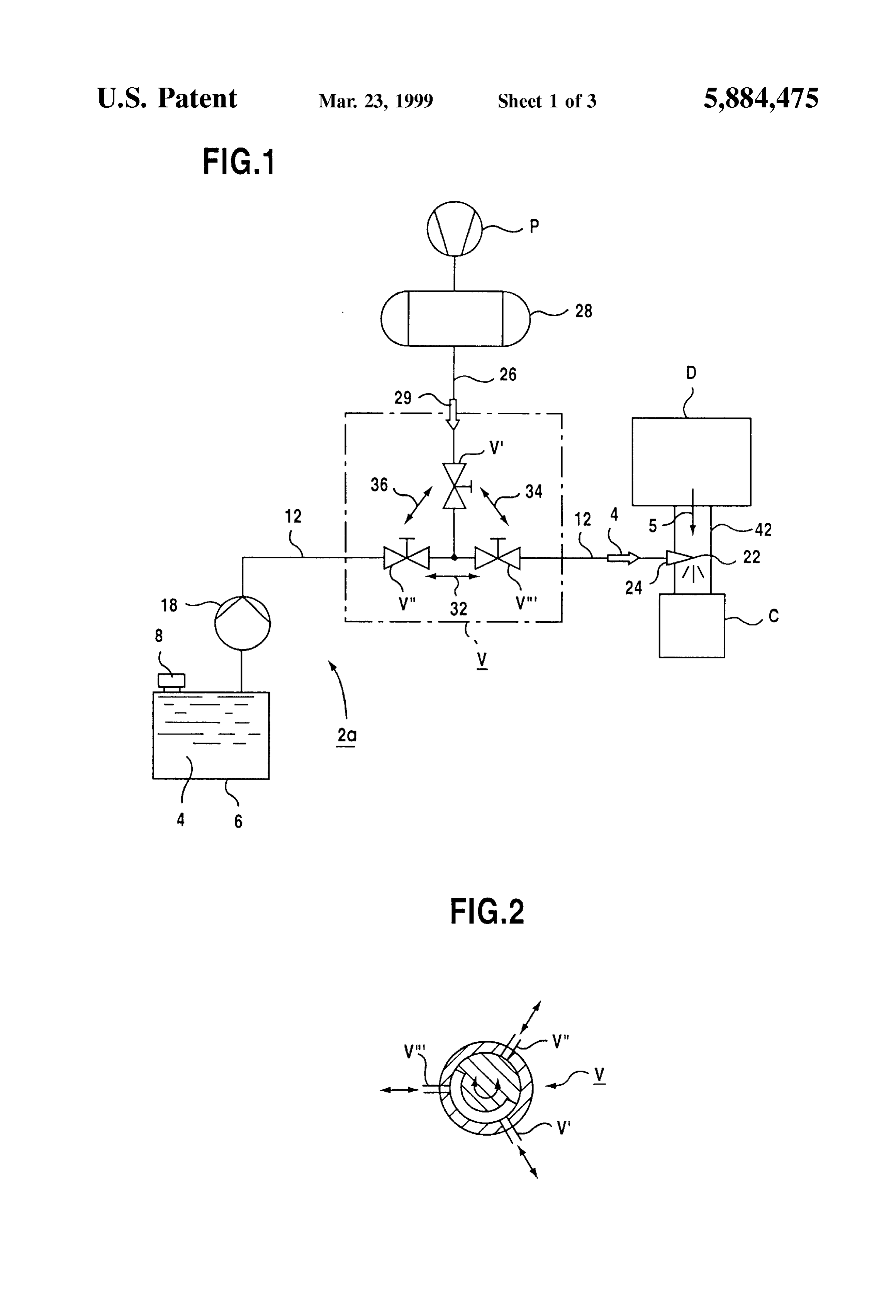
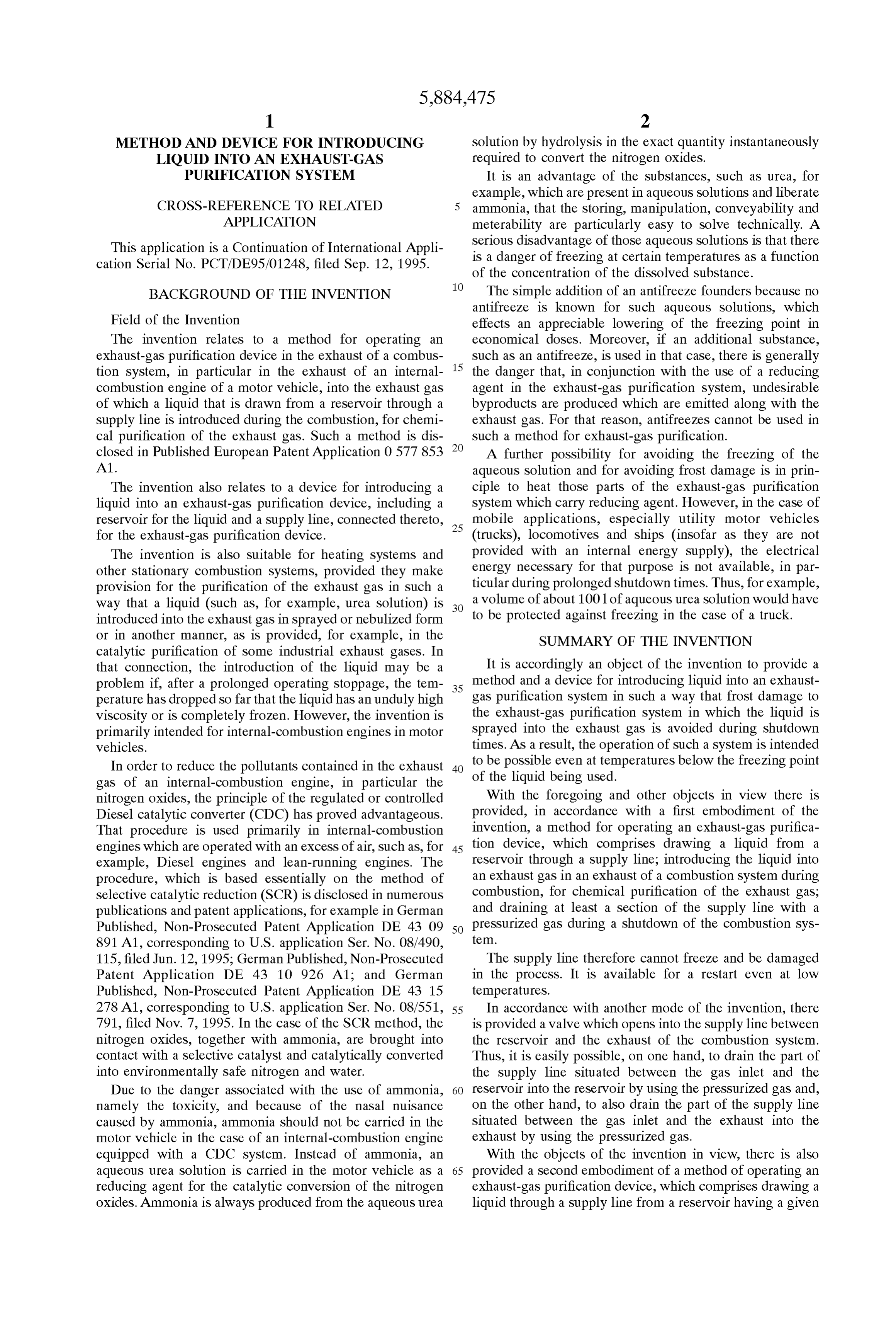
S 6 liquid Supply line. This means in particular that, for a heater catalytic converter C for reducing a proportion of nitrogen operated in this way, Virtually no additional electrical energy oxide by reduction using a urea Solution 4. The catalytic has to be provided from the vehicle battery of the utility converter C may be referred to as an exhaust-gas purification motor vehicle. This is applicable with the exception of small device. The urea Solution 4 is contained initially in a quantities of energy, for example for establishing a Suitable container 6 having a venting device 8. The urea Solution 4 coolant flow rate. can be fed through the use of a feed pump 18 through a In accordance with again a further feature of the Supply line 12 to an outlet opening 22 leading into the invention, there is provided a device assigned to the reser exhaust-gas line 42. A compression pump P feeds a voir for temperature monitoring and/or temperature control. preSSurized-gas container 28 from which a preSSurized-gas In this way, it is possible, for example, not to overheat or Supply line 26 can feed pressurized gas 29 to the liquid locally vaporize the liquid contained in the reservoir. A Supply line 12. Pressurized air can be especially used as the device for temperature monitoring is understood as meaning preSSurized gas 29.
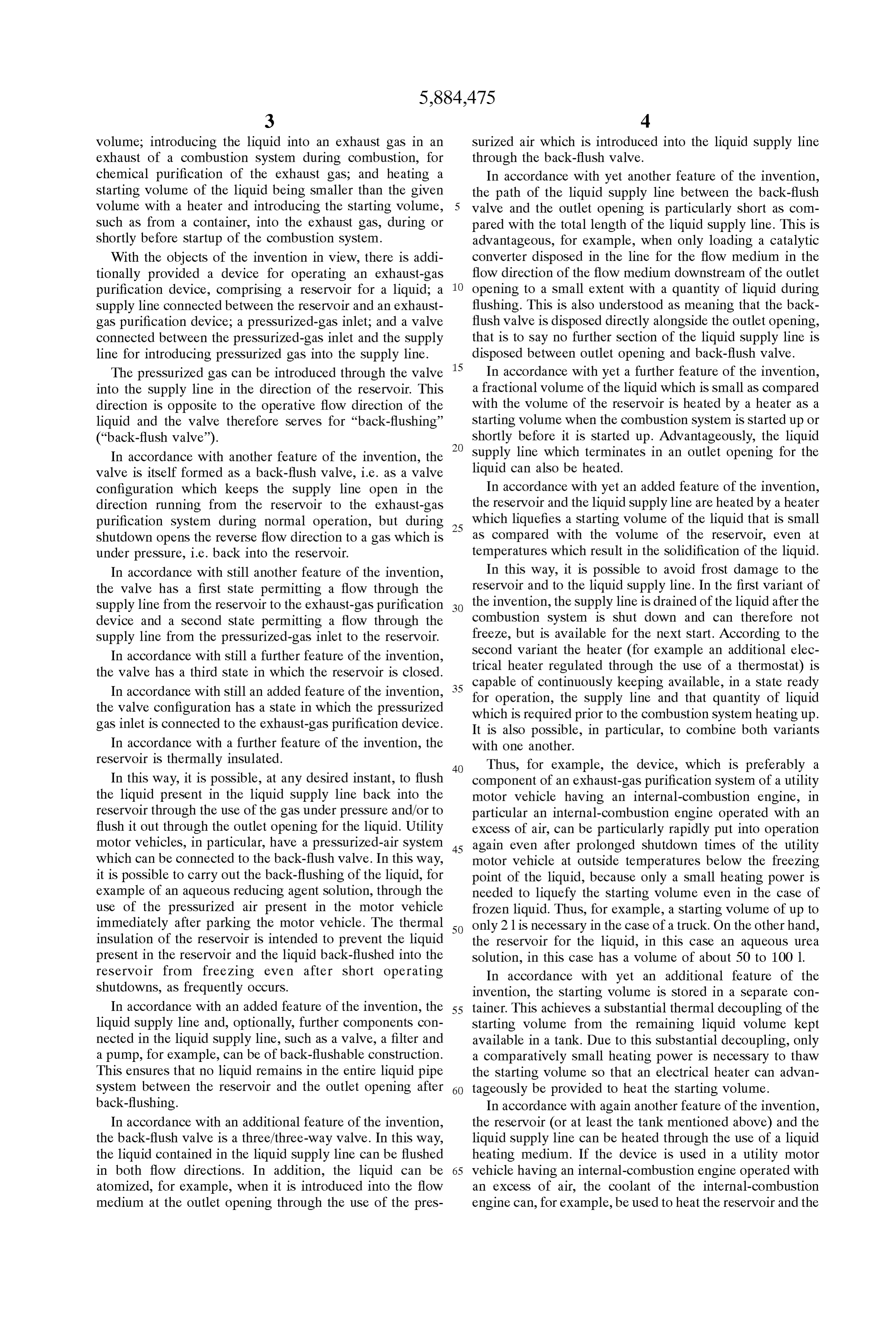
temperature Sensors Such as, for example, thermocouples, The pressurized gas 29 is supplied from the container 28 resistance thermometers and the like. Devices for tempera through a valve configuration V, which includes valves V', ture control are, for example, a heat eXchanger heated 15 V" and V" according to FIG. 1. According to FIG. 2, the through the use of the coolant of the internal-combustion valves V, V" and V" may also be individually closable engine, with the quantity of coolant flowing through the heat connections. The pressurized-gas Supply line 26 can be shut eXchanger per unit time being controlled through the use of off through the use of the valve V' so that in accordance with an adjustable valve. In this connection, the adjustable valve this function (shown as an arrow 32 in FIG. 1) the aqueous can be controlled, for example, directly or indirectly by the urea solution 4 is fed out of the container 6 through the line Signals of the device for temperature monitoring. 12 to the outlet opening 22 in the exhaust-gas line 42. In accordance with again an added feature of the The feed pump 18 can be formed, in particular, as a invention, in order to reliably avoid frost damage to the back-flushable pump, i.e. a flow can also take place through device during the shutdown times of a utility motor vehicle 25 the pump 18 against the feed direction after Shutting down. at temperatures below the freezing point of the liquid, for If the combustion System, i.e. the Diesel engine D is example an aqueous urea Solution, the liquid Supply line is turned off, for example by turning the ignition key, the valve provided with a back-flush valve to which a gas that is under V" is opened and the pressurized gas 29 is released from the preSSure can be applied. In this way, the liquid Supply line container 28, but the outlet opening 22 in the path of the and other components disposed in the liquid Supply line are exhaust-gas 5 is blocked (for example by closing the valve kept free of liquid. The latter would otherwise cause damage V"). In this function, which is shown as an arrow 36, the as a result of the increase in Volume occurring during pressurized gas 29 from the container 28 flushes the urea freezing. Solution 4 out of the line 12 back into the container 6. As a Other features which are considered as characteristic for result of opening the valve V" and closing the valve V", the the invention are set forth in the appended claims. 35 preSSurized-gas container 28 can then also be drained Although the invention is illustrated and described herein through the outlet opening 22 into the exhaust-gas line 42 as embodied in a method and a device for introducing liquid and consequently into the catalytic converter C, which is a into an exhaust-gas purification System, it is nevertheless not function shown as an arrow 34. In a Subsequent rest position, intended to be limited to the details shown, Since various which again corresponds to the function 32, the Supply line modifications and Structural changes may be made therein 40 12 Serves as a pressure equalization line in order to vent the without departing from the spirit of the invention and within container 6 and the pump 18. However, a separate non the Scope and range of equivalents of the claims. illustrated pressure equalization line can also be provided. The construction and method of operation of the The supply line 12 can then remain blocked in the rest position.
invention, however, together with additional objects and advantages thereof will be best understood from the follow 45 Various constructions are possible for the multi-way valve ing description of Specific embodiments when read in con V. In principle it is Sufficient that the pressurized-gas Supply nection with the accompanying drawings. line 26 is closed during normal operation of the combustion system D, but is open when the system D and the pumps 18
BRIEF DESCRIPTION OF THE DRAWINGS and Pare shut down So that the pressurized-gas container 28 50 drains simultaneously into the exhaust-gas line 42 and into
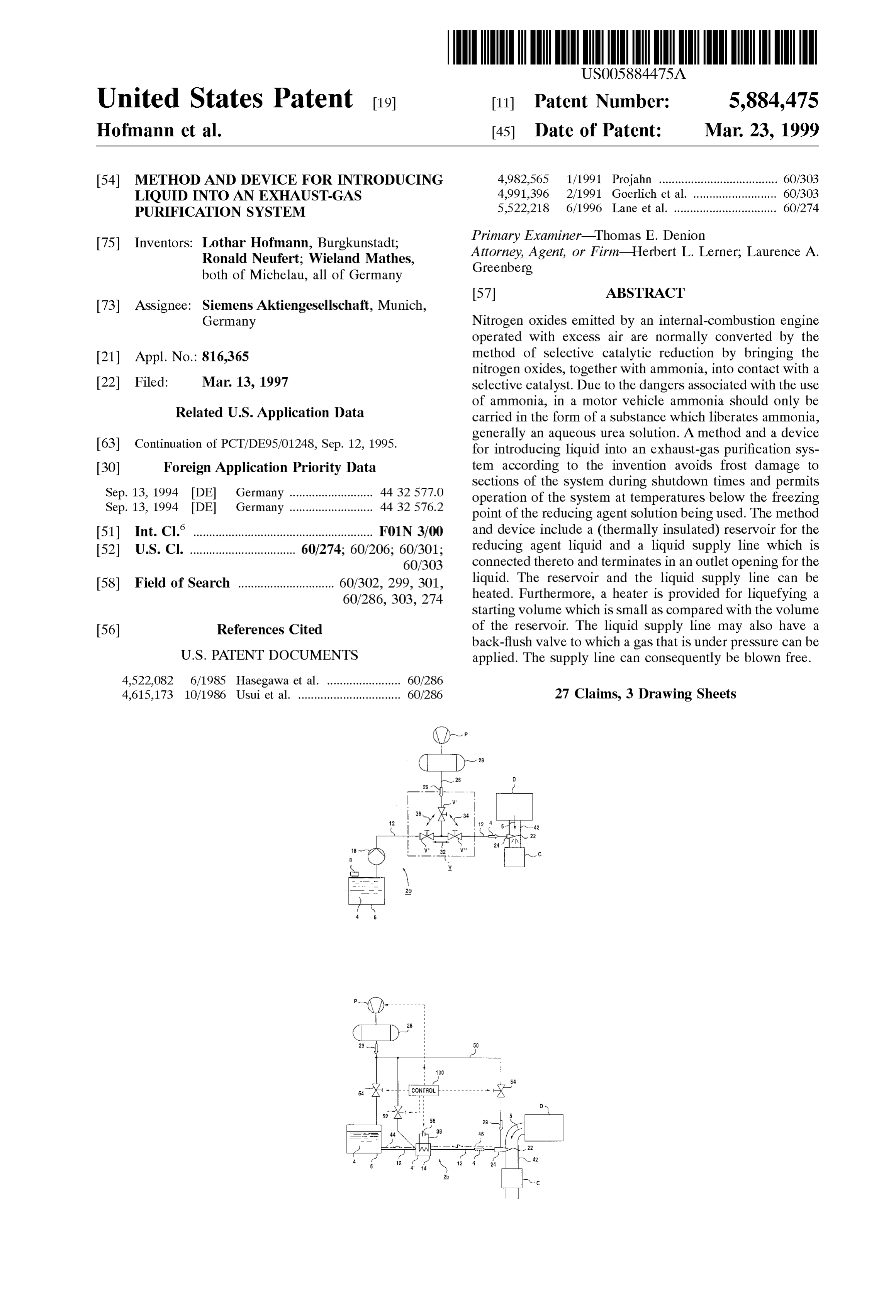
FIG. 1 is a Schematic and block circuit diagram of a first the container 6. It is possible, in particular, to control the embodiment of the invention; valve configuration V and the pumps 18 and P through the FIG. 2 is a croSS-Sectional view of a mechanical multi use of a vehicle computer 100 of the respective motor way valve which can be used as a back-flush valve in a liquid vehicle, which is shown in FIG. 3.
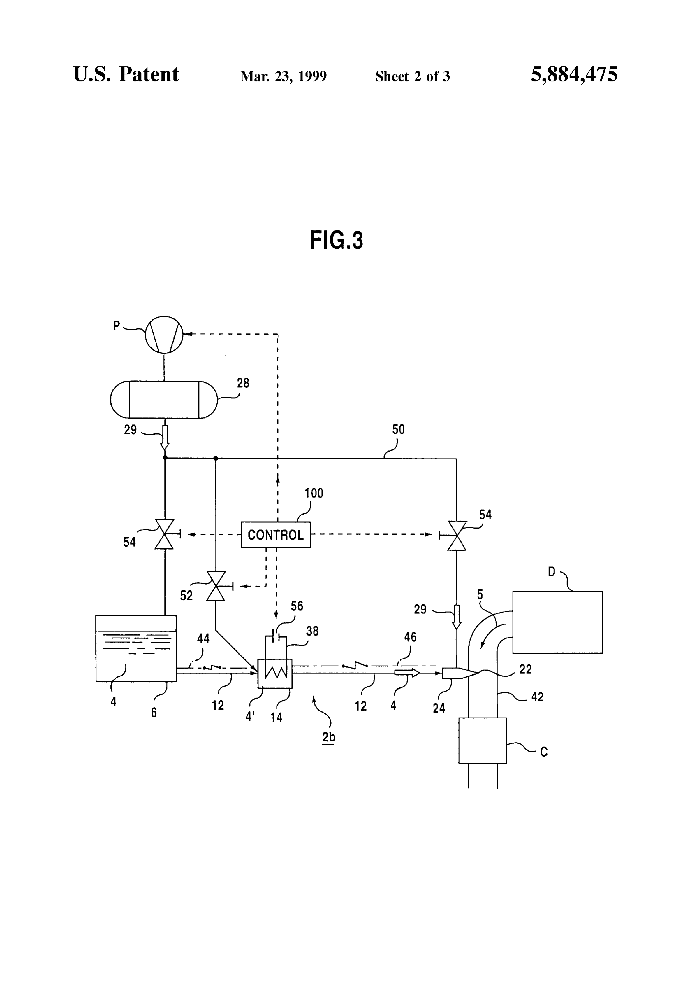
Supply line according to FIG. 1; 55 FIG. 3 shows, by way of example, a device 2b in which FIG. 3 is a Schematic and block circuit diagram of a the pump Pand the pressurized container 28 are also used to Second embodiment of the invention; and Spray the urea Solution 4 from the container 6 through the FIG. 4 is a Schematic and block circuit diagram of a Supply line 12 into the exhaust-gas line 42. In this case, the preferred combination of the two embodiments. outlet opening 22 is formed as an outlet opening of a nozzle 60 24. The pressurized air 29 in this case Serves as a propellant
DESCRIPTION OF THE PREFERRED for the nozzle 24 and a suitable pressurized-air line 50 EMBODIMENTS permits control by the vehicle computer 100 (“control') Referring now to the figures of the drawings in detail and through the use of valves 54.
first, particularly, to FIG. 1 thereof, there is seen a Diesel In order to provide the urea solution 4 there is provided engine D as a preferred application example of a combustion 65 not only the normal tank 6, but also an intermediate con System. Exhaust gas 5 from the Diesel engine D is fed in a tainer 14 connected in the liquid supply line 12. The volume device 2a through an exhaust-gas line or exhaust 42 to a of the intermediate container 14 contains only a fraction of
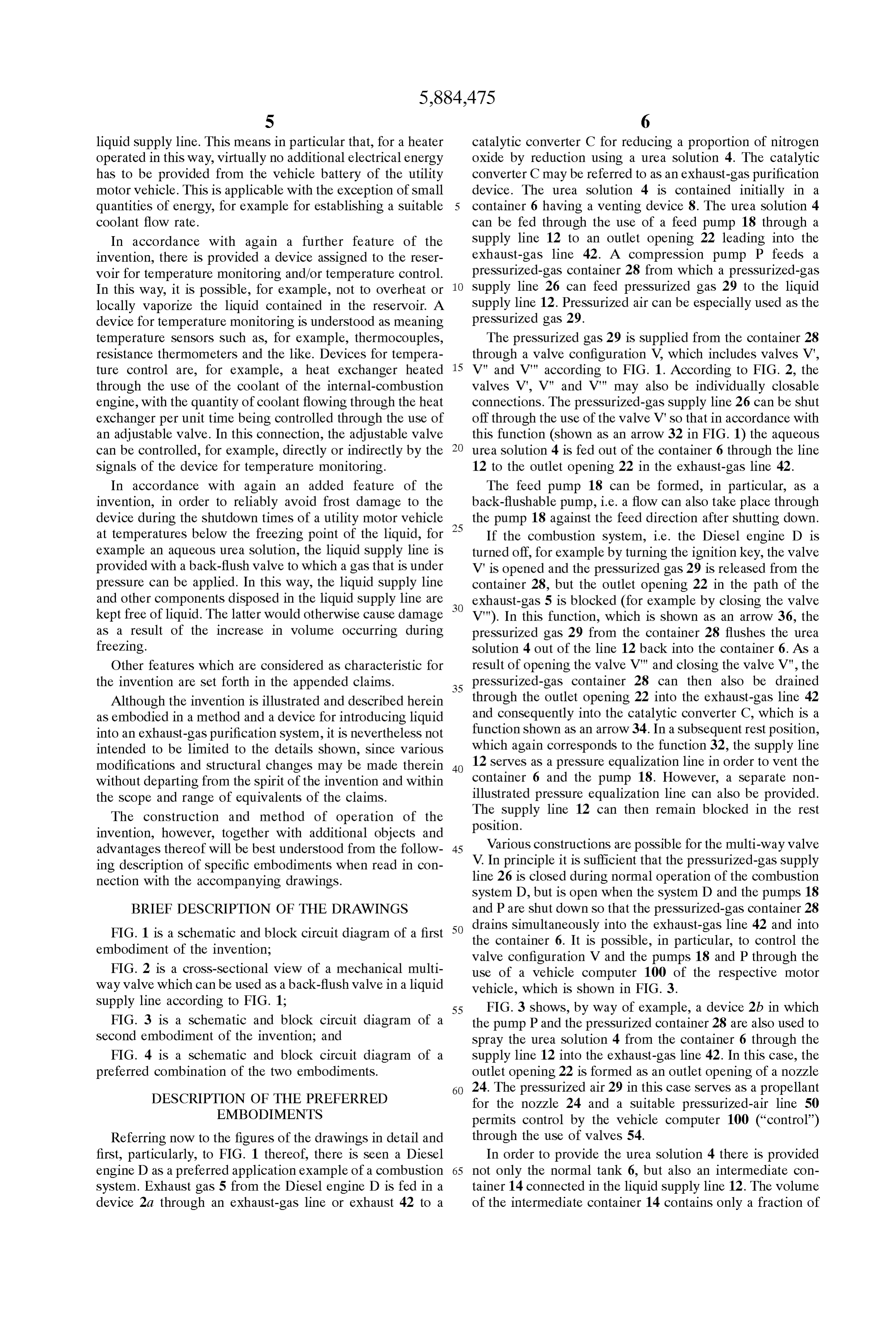
Page 8
the Volume which the urea tank 6 is able to accommodate. operating case, a Small Starting Volume 4 of the urea The intermediate container 14 consequently provides a Small Solution 4 in the container 14 which serves as intermediate Volume that acts as a starting Volume 4 which is precisely container can then be thawed either after Starting up the dimensioned in Such a way that the combustion System D internal-combustion engine or even before starting up the can be operated for a certain time (for example half an hour), internal-combustion engine, through the use of an electrical which is needed for the entire system D to heat up. This heater 38 which supplies a heat exchanger 40 with heat. The warming-up time is Sufficient to thaw the Volume of the pump 18 then feeds this thawed urea solution 4 through the container 6 if the liquid 4 contained therein should have been filter 16 and the back-flush valve 20 (when in the function frozen after a long operating shutdown. 32) to the outlet opening 22. There the aqueous urea Solution The intermediate container 14 has a heater 38 which is 4 is finely sprayed into the exhaust gas 5 which flows into the exhaust-gas line 42 of the internal-combustion engine. In formed, for example, as an additional electrical heater and order to ensure that the urea Solution 4 does not freeze in the can be fed from a battery 56. Advantageously, a heating line urea Supply line 12 on its way to the outlet opening 22, a 44, 46 which can rapidly thaw the Supply line 12 after a heater, which is indicated by dash-dot lines 44, 46 parallel prolonged operating shutdown is also connected to the battery 56. A controllable shutoff valve 52 makes possible 15 to the urea Supply line 12, may additionally be provided for the delivery of liquid from the intermediate container 14 the can urea Supply line 12. In this connection, the heat energy be Supplied electrically or, alternatively, through the even during the time in which the liquid 4 in the container coolant of the internal-combustion engine. Thus, it is pos 6 may still be frozen. sible for the urea supply line 12 to be constructed like a A Separate non-illustrated pressure equalization line can coaxial line in which the urea Solution 4 flows in a central also be provided in this case between the liquid container 6 core and the coolant flows in an outer jacket. At the same and the exhaust-gas channel 42 of the engine D, the preSSurized-gas line can be formed in Such a way that it time, the engine coolant, insofar as it is passed through the coaxial line, can be heated electrically.
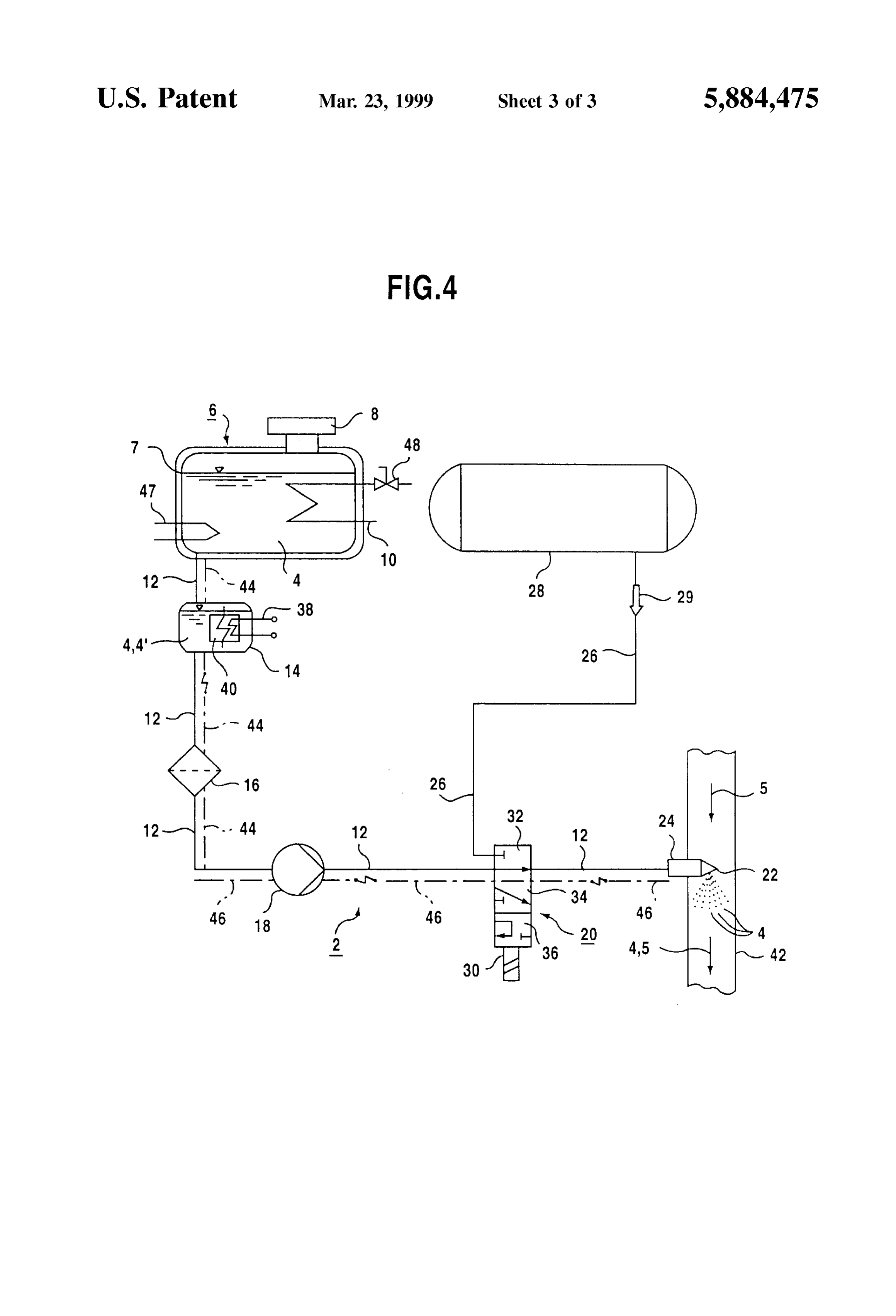
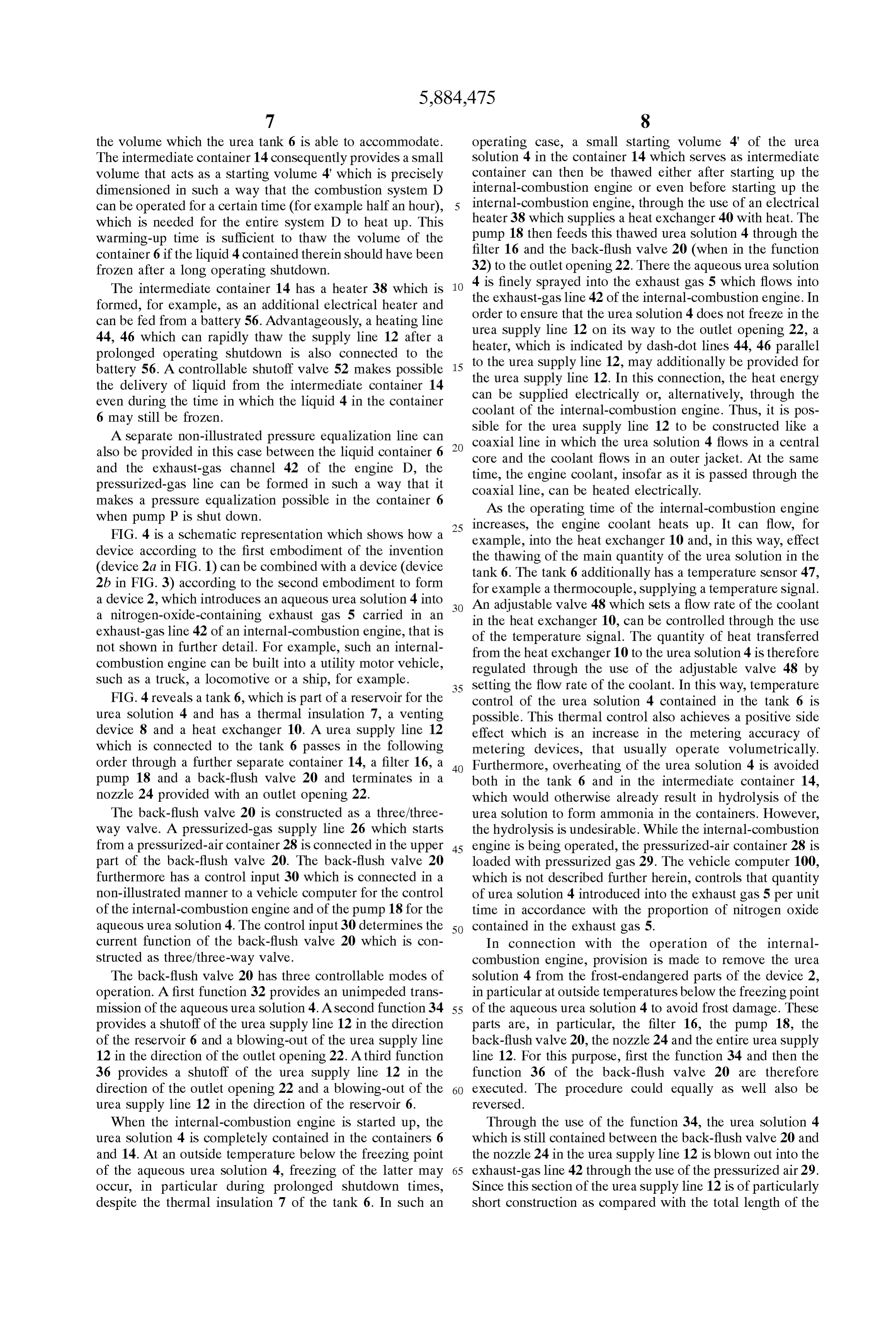
makes a pressure equalization possible in the container 6 AS the operating time of the internal-combustion engine when pump P is shut down. 25 increases, the engine coolant heats up. It can flow, for FIG. 4 is a schematic representation which shows how a example, into the heat eXchanger 10 and, in this way, effect device according to the first embodiment of the invention the thawing of the main quantity of the urea Solution in the (device 2a in FIG. 1) can be combined with a device (device tank 6. The tank 6 additionally has a temperature sensor 47, 2b in FIG. 3) according to the second embodiment to form for example a thermocouple, Supplying a temperature Signal. a device 2, which introduces an aqueous urea Solution 4 into An adjustable valve 48 which sets a flow rate of the coolant a nitrogen-oxide-containing exhaust gas 5 carried in an in the heat eXchanger 10, can be controlled through the use exhaust-gas line 42 of an internal-combustion engine, that is of the temperature Signal. The quantity of heat transferred not shown in further detail. For example, Such an internal from the heat exchanger 10 to the urea solution 4 is therefore combustion engine can be built into a utility motor vehicle, regulated through the use of the adjustable valve 48 by Such as a truck, a locomotive or a ship, for example. 35 Setting the flow rate of the coolant. In this way, temperature FIG. 4 reveals a tank 6, which is part of a reservoir for the control of the urea Solution 4 contained in the tank 6 is urea Solution 4 and has a thermal insulation 7, a venting possible. This thermal control also achieves a positive side device 8 and a heat eXchanger 10. Aurea Supply line 12 effect which is an increase in the metering accuracy of which is connected to the tank 6 passes in the following metering devices, that usually operate Volumetrically. order through a further separate container 14, a filter 16, a 40 Furthermore, overheating of the urea Solution 4 is avoided pump 18 and a back-flush valve 20 and terminates in a both in the tank 6 and in the intermediate container 14, nozzle 24 provided with an outlet opening 22. which would otherwise already result in hydrolysis of the The back-flush valve 20 is constructed as a three/three urea Solution to form ammonia in the containers. However, way valve. A pressurized-gas Supply line 26 which starts the hydrolysis is undesirable. While the internal-combustion from a pressurized-air container 28 is connected in the upper 45 engine is being operated, the pressurized-air container 28 is part of the back-flush valve 20. The back-flush valve 20 loaded with pressurized gas 29. The vehicle computer 100, furthermore has a control input 30 which is connected in a which is not described further herein, controls that quantity non-illustrated manner to a vehicle computer for the control of urea Solution 4 introduced into the exhaust gas 5 per unit of the internal-combustion engine and of the pump 18 for the time in accordance with the proportion of nitrogen oxide acqueous urea solution 4. The control input 30 determines the 50 contained in the exhaust gas 5.
current function of the back-flush valve 20 which is con In connection with the operation of the internal Structed as three/three-way valve. combustion engine, provision is made to remove the urea The back-flush valve 20 has three controllable modes of Solution 4 from the frost-endangered parts of the device 2, operation. A first function 32 provides an unimpeded trans in particular at outside temperatures below the freezing point mission of the aqueous urea Solution 4. A Second function 34 55 of the aqueous urea Solution 4 to avoid frost damage. These provides a shutoff of the urea supply line 12 in the direction parts are, in particular, the filter 16, the pump 18, the of the reservoir 6 and a blowing-out of the urea Supply line back-flush valve 20, the nozzle 24 and the entire urea supply 12 in the direction of the outlet opening 22. A third function line 12. For this purpose, first the function 34 and then the 36 provides a shutoff of the urea supply line 12 in the function 36 of the back-flush valve 20 are therefore direction of the outlet opening 22 and a blowing-out of the 60 executed. The procedure could equally as well also be urea Supply line 12 in the direction of the reservoir 6. reversed.
When the internal-combustion engine is started up, the Through the use of the function 34, the urea solution 4 urea Solution 4 is completely contained in the containerS 6 which is still contained between the back-flush valve 20 and and 14. At an outside temperature below the freezing point the nozzle 24 in the urea Supply line 12 is blown out into the of the aqueous urea Solution 4, freezing of the latter may 65 exhaust-gas line 42 through the use of the pressurized air 29. occur, in particular during prolonged shutdown times, Since this Section of the urea Supply line 12 is of particularly despite the thermal insulation 7 of the tank 6. In such an Short construction as compared with the total length of the
Page 9
urea Supply line 12, only a Small quantity of urea Solution 4 drawing a liquid through a Supply line from a reservoir is also introduced into the exhaust-gas line 42 which then no having a given Volume;
longer has exhaust gas 5 flowing through it. The urea introducing the liquid into an exhaust gas in an exhaust of Solution 4 which is discharged may, for example, evaporate a combustion System during combustion, for chemical at the hot walls of the exhaust-gas line 42. The ammonia purification of the exhaust gas, and produced during the hydrolysis (evaporation) is adsorbed in heating a starting Volume of the liquid being Smaller than the catalytic converter C, which is connected downstream of the given volume with a heater and introducing the the nozzle 24 in the exhaust-gas line 42 and is not shown Starting Volume into the exhaust gas, no later than further herein. during Startup of the combustion System. 6. The method according to claim 5, which comprises
Through the use of the function 36 of the back-flush valve 1O Storing 20, the entire remaining urea Supply line 12, the pump 18 tainer. the Starting Volume of the liquid in a further con disposed therein and the filter 16 disposed therein are then 7. The method according to claim 3, which comprises flushed with the pressurized air 29 and rendered urea-free. introducing an aqueous urea Solution as the liquid into the Provision is made in this case for the size of the reservoir 14 15 exhaust gas of an internal-combustion engine of a motor
Serving as an intermediate container to be chosen in Such a vehicle as the combustion System.
way that the Volume is Sufficient for accommodating the 8. The...method according to claim 7, which comprises back-flushed urea Solution 4 including an expansion Volume operating the internal-combustion engine operated with an filled with air. The back-flushed urea Solution 4 is then used excess of air.
as a starting Volume which can be thawed if necessary with 9. A device for operating an exhaust-gas purification only a Small electrical heating power when the internal device, comprising:
combustion engine is started up again. a reservoir for a liquid;
A venting line/pressure relief line which opens into the a Supply line connected between said reservoir and an exhaust-gas line 42 upstream of the non-illustrated catalytic exhaust-gas purification device; converter, as Seen in the flow direction of the exhaust gas 5, 25 a pressurized-gas inlet, and for the purpose of nitrogen oxide reduction, can be con a valve connected between Said pressurized-gas inlet and nected to the reservoir 6 and, optionally, also to the reservoir Said Supply line for introducing preSSurized gas into 14 in a manner which is not shown further, but is disclosed, Said Supply line in a direction towards Said reservoir. for example, in Published European Patent Application 0 10. The device according to claim 9, wherein said valve 577 853 A1. is a back-flush valve disposed in Said Supply line. 11. The device according to claim 10, including further
The device 2 described above consequently ensures that at back-flushable all times, regardless of the outside temperature, the quantity Structural components disposed in Said liquid of urea necessary to catalytically convert the nitrogen oxides Supply line between Said valve and Said reservoir. can always be provided during the operation of the internal has12.a first The device according to claim 9, wherein Said valve combustion engine. It also ensures that the entire device 2 is 35 from Said State permitting a flow through Said Supply line protected against frost damage at Outside temperatures and a Secondreservoir State to the exhaust-gas purification device permitting a flow through said Supply line below the freezing point of the urea Solution 4. from Said pressurized-gas inlet to Said reservoir. In addition, the invention can also be used in chemical 13. The device according to claim 12, wherein said valve industry Systems in which liquids are carried through out has a third State in which said reservoir is closed. door lines.
We claim:
40 14. The device according to claim 12, wherein said valve 1. A method for operating an exhaust-gas purification is connected to the exhaust-gas purification device. inlet configuration has a State in which Said preSSurized-gas device, which comprises: 15. The device according to claim 13, wherein said valve drawing a liquid from a reservoir through a Supply line; configuration has a State in which Said preSSurized-gas inlet introducing the liquid into an exhaust gas in an exhaust of 45 is connected to the exhaust-gas purification device. a combustion System during combustion, for chemical 16. The device according to claim 9, wherein the pres purification of the exhaust gas, and Surized gas is introduced into Said Supply line at a location draining at least a Section of the Supply line with a immediately alongside the exhaust-gas purification device. preSSurized gas during a shutdown of the combustion 17. The device according to claim 9, wherein the pres System. 50 Surized gas is introduced into Said Supply line at a location 2. The method according to claim 1, which comprises nearer to the exhaust-gas purification device than to Said feeding the pressurized gas through a pressurized-gas inlet reservoir.
and a valve into the Supply line between the reservoir and the 18. The device according to claim 9, including a device exhaust of the combustion System, for draining a part of the for heating Said liquid Supply line.
Supply line between the pressurized-gas inlet and the reser 55 19. The device according to claim 18, wherein said voir into the reservoir, and for draining a part of the Supply reservoir has a given Volume, and including an intermediate line between the pressurized-gas inlet and the exhaust into container associated with Said heatable liquid Supply line for the exhaust. a volume of the liquid Smaller than Said given Volume. 3. The method according to claim 1, which comprises 20. The device according to claim 9, wherein said reser introducing an aqueous urea Solution as the liquid into the 60 voir has a given Volume, and including a heater for lique exhaust gas of an internal-combustion engine of a motor fying a Starting Volume of the liquid Smaller than Said given vehicle as the combustion System. Volume.
4. The method according to claim 3, which comprises 21. The device according to claim 20, wherein said heater operating the internal-combustion engine operated with an for the Starting Volume is ad electrical heater. excess of air. 65 22. The device according to claim 20, wherein said 5. A method of operating an exhaust-gas purification reservoir is a tank, and including an intermediate container device, which comprises: accommodating the Starting Volume.
Page 10
23. The device according to claim 22, including a device a reservoir for a liquid;
for heating at least Said tank and Said Supply line with a a Supply line connected between said reservoir and an liquid heating medium. exhaust-gas purification device; 24. The device according to claim 20, including a device a pressurized-gas inlet, and for heating Said Supply line electrically. a valve connected between Said pressurized-gas inlet and 25. The device according to claim 20, including a device Said Supply line for introducing preSSurized gas into asSociated with Said reservoir for at least one of temperature Said Supply line in a direction towards Said reservoir. monitoring and temperature control. 27. The system according to claim 26, wherein the 26. An exhaust-gas purification System of a utility motor 1O internal-combustion engine is operated with an excess of air. vehicle having an internal-combustion engine, the System comprising:
Provenance
- Collection
- Cited prior art
- Original PDF
- patentimages.storage.googleapis.com →
- Filed
- 1997-03-13
- Pages
- 10
- Method
- pdftotext (the PDF's own text layer) + pdftoppm 300dpi page scans
- Source
- Google Patents bibliographic record
- Granted
- 1999-03-23
- Inventors
- Lothar Hofmann; Ronald Neufert; Wieland Mathes; Siemens AG
- Transcribed from
- patentimages.storage.googleapis.com →