patent · US4123663
Gas-etching device
31 October 1978
Page 1 — bibliographic record
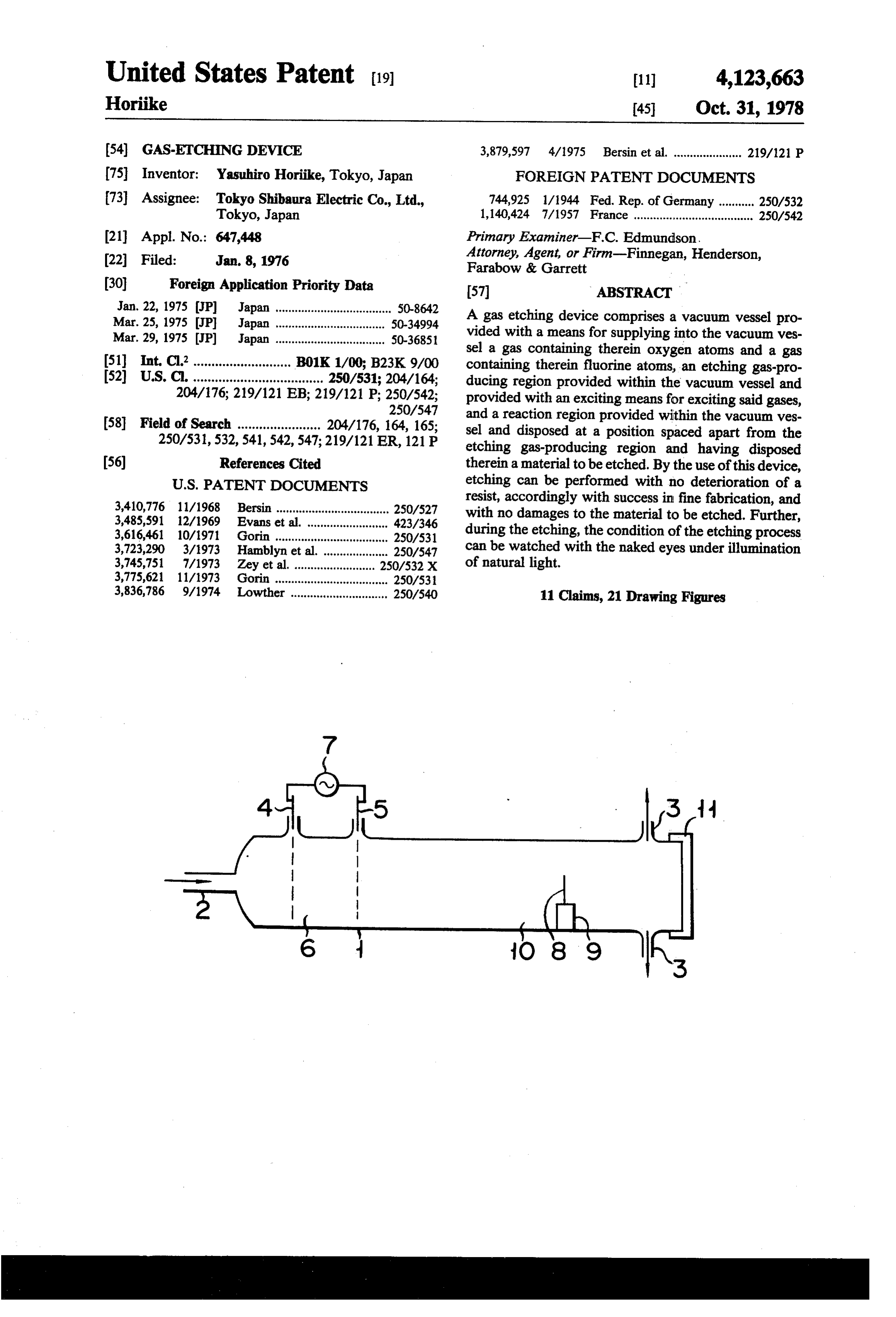
United States Patent (19) 11) 4,123,663 Horike 45 Oct. 31, 1978 (54) GAS-ETCHING DEVICE 3,879,597 4/1975 Bersin et al. ..................... 219/121 P 75 Inventor: Yasuhiro Horike, Tokyo, Japan FOREIGN PATENT DOCUMENTS 73 Assignee: Tokyo Shibaura Electric Co., Ltd., 744,925 1/1944 Fed. Rep. of Germany ........... 250/.532 Tokyo, Japan 1,140,424 7/1957 France ..................................... 250/542 21 Appl. No.: 647,448 Primary Examiner-F.C. Edmundson. (22 Filed: Jan. 8, 1976 Attorney, Agent, or Firm-Finnegan, Henderson, Farabow & Garrett (30) Foreign Application Priority Data 57 ABSTRACT Jan. 22, 1975 JP Japan .................................... S0-8642 A gas etching device comprises a vacuum vessel pro Mar. 25, 1975 JP Japan ......... ... 50-34994
Mar. 29, 1975 (JP) Japan .................................. 50-3685 vided with a means for supplying into the vacuum ves sel a gas containing therein oxygen atoms and a gas 51 Int. C.’........................... B01K 1/00; B23K9/00 containing therein fluorine atoms, an etching gas-pro 52 U.S. C. .................................... 250/531; 204/164; ducing region provided within the vacuum vessel and 204/176; 219/121 EB; 219/121 P; 250/542; provided with an exciting means for exciting said gases, 250/547 and a reaction region provided within the vacuum ves 58 Field of Search ....................... 204/176, 164, 165; sel and disposed at a position spaced apart from the 250/531,532,541,542, 547; 219/121 ER, 121 P etching gas-producing region and having disposed 56) References Cited therein a material to be etched. By the use of this device,
3,410,776 11/1968 Bersin ................................... 250/527 resist, accordingly with success in fine fabrication, and 3,485,591 12/1969 Evans et al. ......................... 423/346 with no damages to the material to be etched. Further, 3,616,461 10/1971 Gorin ............. ... 250/531 during the etching, the condition of the etching process 3,723,290 3/1973 Hamblyn et al..................... 250/547 can be watched with the naked eyes under illumination 3,745,751 7/1973 Zey et al. ... ... 250/.532X of natural light.
3,775,621 11/1973 Gorin ................................... 250/53 3,836,786 9/1974 Lowther .............................. 250/540 11 Claims, 21 Drawing Figures
Page 2
Drawing sheet — no readable text.
Page 3
Drawing sheet — no readable text.
Page 4
Drawing sheet — no readable text.
Page 5
Drawing sheet — no readable text.
Page 6
Drawing sheet — no readable text.
Page 7
Drawing sheet — no readable text.
Page 8
Drawing sheet — no readable text.
Page 9
Drawing sheet — no readable text.
Page 10
Drawing sheet — no readable text.
Page 11
Drawing sheet — no readable text.
Page 12
(5) During the watching of the etching condition, an
GAS.ETCHING DEVICE undesirable effect of said ultraviolet rays upon the BACKGROUND OF THE INVENTION naked eyes is produced.
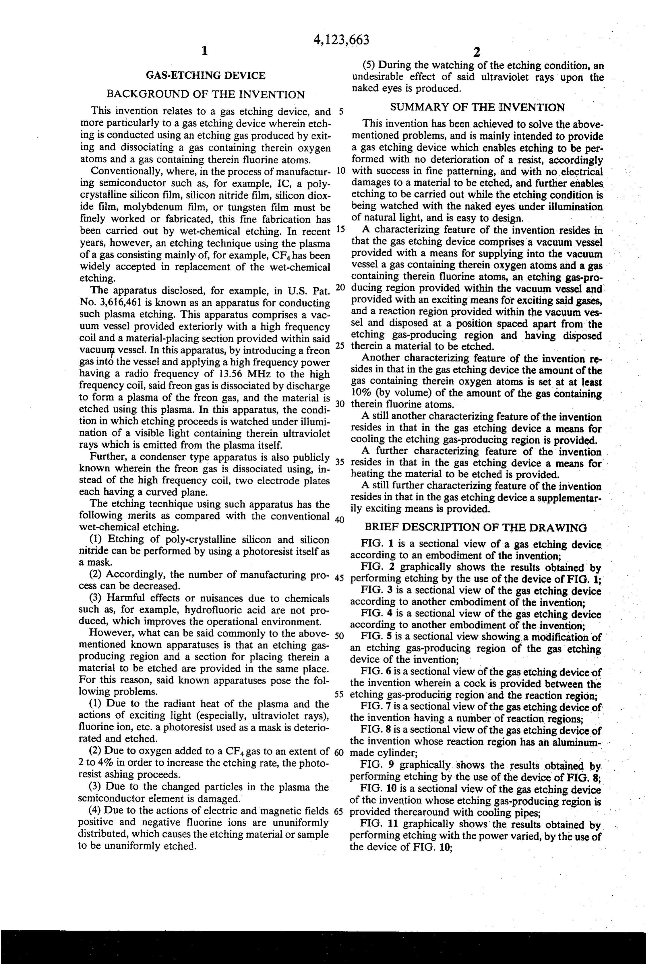
This invention relates to a gas etching device, and SUMMARY OF THE INVENTION more particularly to a gas etching device wherein etch This invention has been achieved to solve the above ing is conducted using an etching gas produced by exit mentioned problems, and is mainly intended to provide ing and dissociating a gas containing therein oxygen a gas etching device which enables etching to be per atoms and a gas containing therein fluorine atoms. formed with no deterioration of a resist, accordingly Conventionally, where, in the process of manufactur O with success in fine patterning, and with no electrical ing semiconductor such as, for example, IC, a poly damages to a material to be etched, and further enables crystalline silicon film, silicon nitride film, silicon diox etching to be carried out while the etching condition is ide film, molybdenum film, or tungsten film must be being watched with the naked eyes under illumination finely worked or fabricated, this fine fabrication has of natural light, and is easy to design. been carried out by wet-chemical etching. In recent 15 A characterizing feature of the invention resides in years, however, an etching technique using the plasma that the gas etching device comprises a vacuum vessel of a gas consisting mainly of, for example, CF4 has been provided with a means for supplying into the vacuum widely accepted in replacement of the wet-chemical vessel a gas containing therein oxygen atoms and a gas etching. containing therein fluorine atoms, an etching gas-pro The apparatus disclosed, for example, in U.S. Pat. 20 ducing region provided within the vacuum vessel and No. 3,616,461 is known as an apparatus for conducting provided with an exciting means for exciting said gases, such plasma etching. This apparatus comprises a vac and a reaction region provided within the vacuum ves uum vessel provided exteriorly with a high frequency sel and disposed at a position spaced apart from the coil and a material-placing section provided within said etching gas-producing region and having disposed vacuum vessel. In this apparatus, by introducing a freon 25 therein gas into the vessel and applying a high frequency power a material to be etched.
Another characterizing feature of the invention re- .
having a radio frequency of 13.56 MHz to the high sides in that in the gas etching device the amount of the frequency coil, said freon gas is dissociated by discharge gas containing therein oxygen atoms is set at at least to form a plasma of the freon gas, and the material is 10% (byfluorine volume) of the amount of the gas containing etched using this plasma. In this apparatus, the condi 30 therein atoms. tion in which etching proceeds is watched under illumi resides in that incharacterizing
A still another feature of the invention the gas etching device a means for nation of a visible light containing therein ultraviolet cooling the etching gas-producing region is provided, rays which is emitted from the plasma itself.
Further, a condenser type apparatus is also publicly 35 resides in thatcharacterizing
A further feature of the invention known wherein the freon gas is dissociated using, in heating the material to be etched isdevice in the gas etching a means for provided.
stead of the high frequency coil, two electrode plates A still further characterizing feature of the invention each having a curved plane. resides in that in the gas etching device a supplementar The etching tecnhique using such apparatus has the ily exciting means is provided. following merits as compared with the conventional wet-chemical etching. BRIEF DESCRIPTION OF THE DRAWING (1) Etching of poly-crystalline silicon and silicon nitride can be performed by using a photoresist itself as according1 isto aansectional
embodiment of the invention;
a mask.
(2) Accordingly, the number of manufacturing pro 45 performing etching by the use the
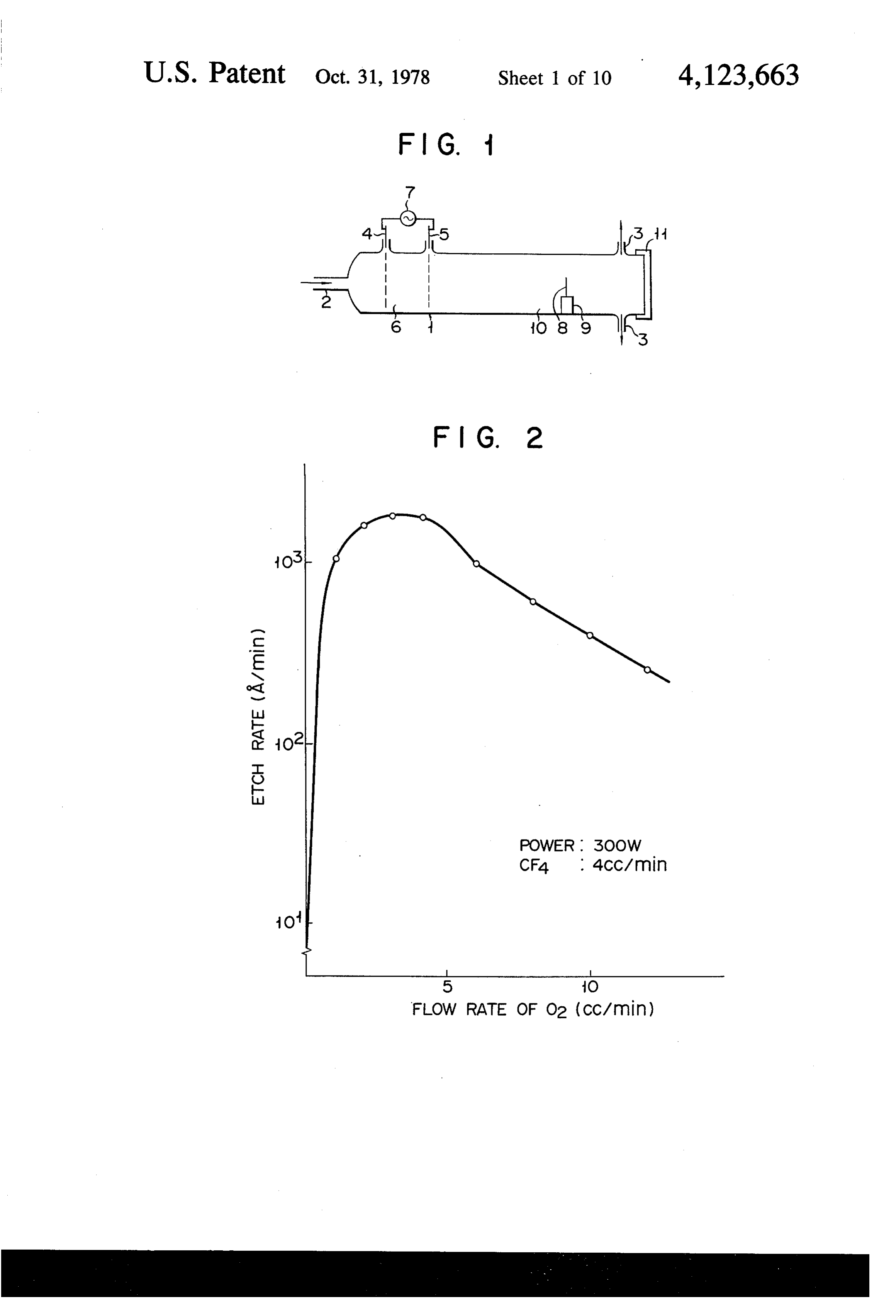
FIG. 2 graphically shows
results obtained by the device of FIG. 1;
cess can be decreased.
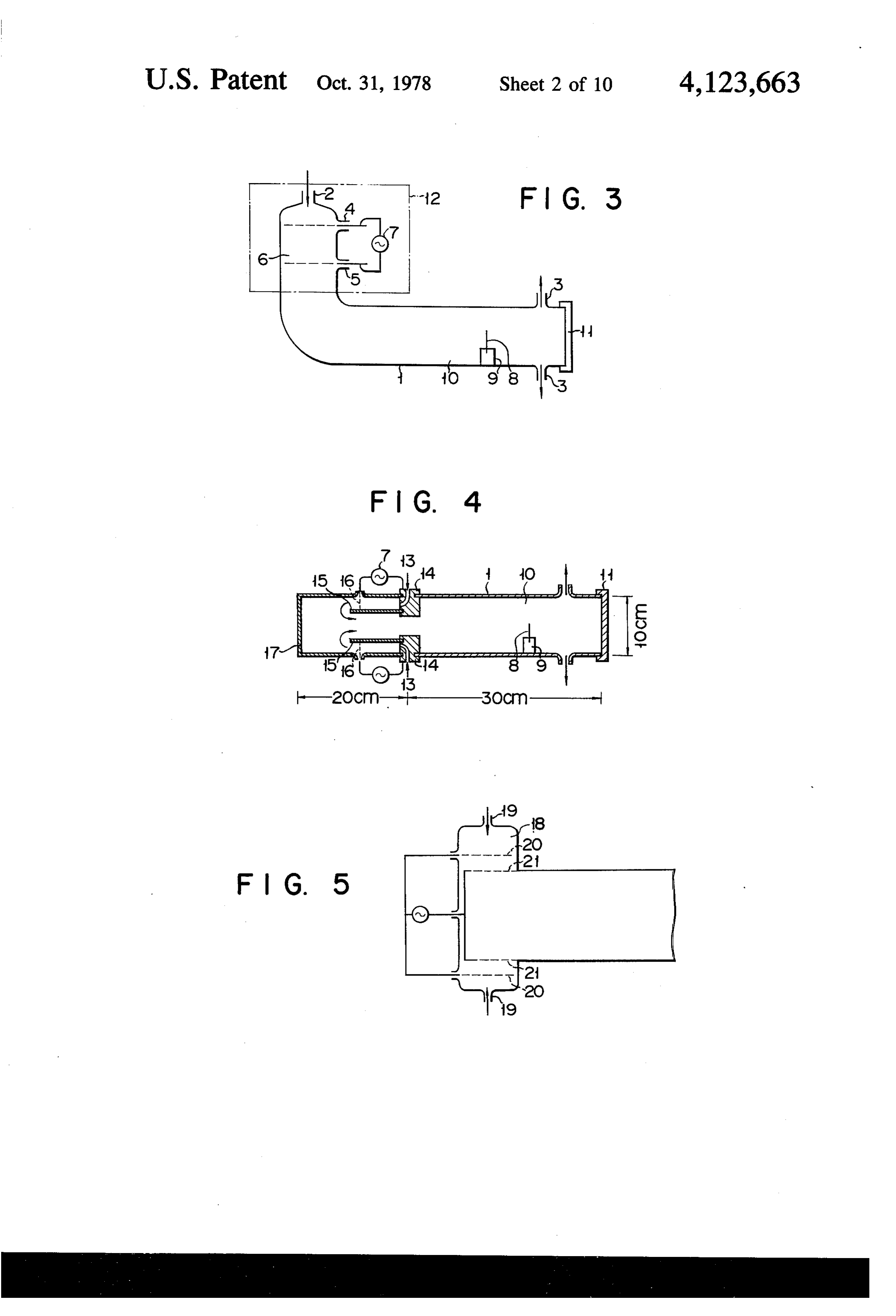
(3) Harmful effects or nuisances due to chemicals according to another embodiment of theetching FIG. 3 is a sectional view of the gas device invention;
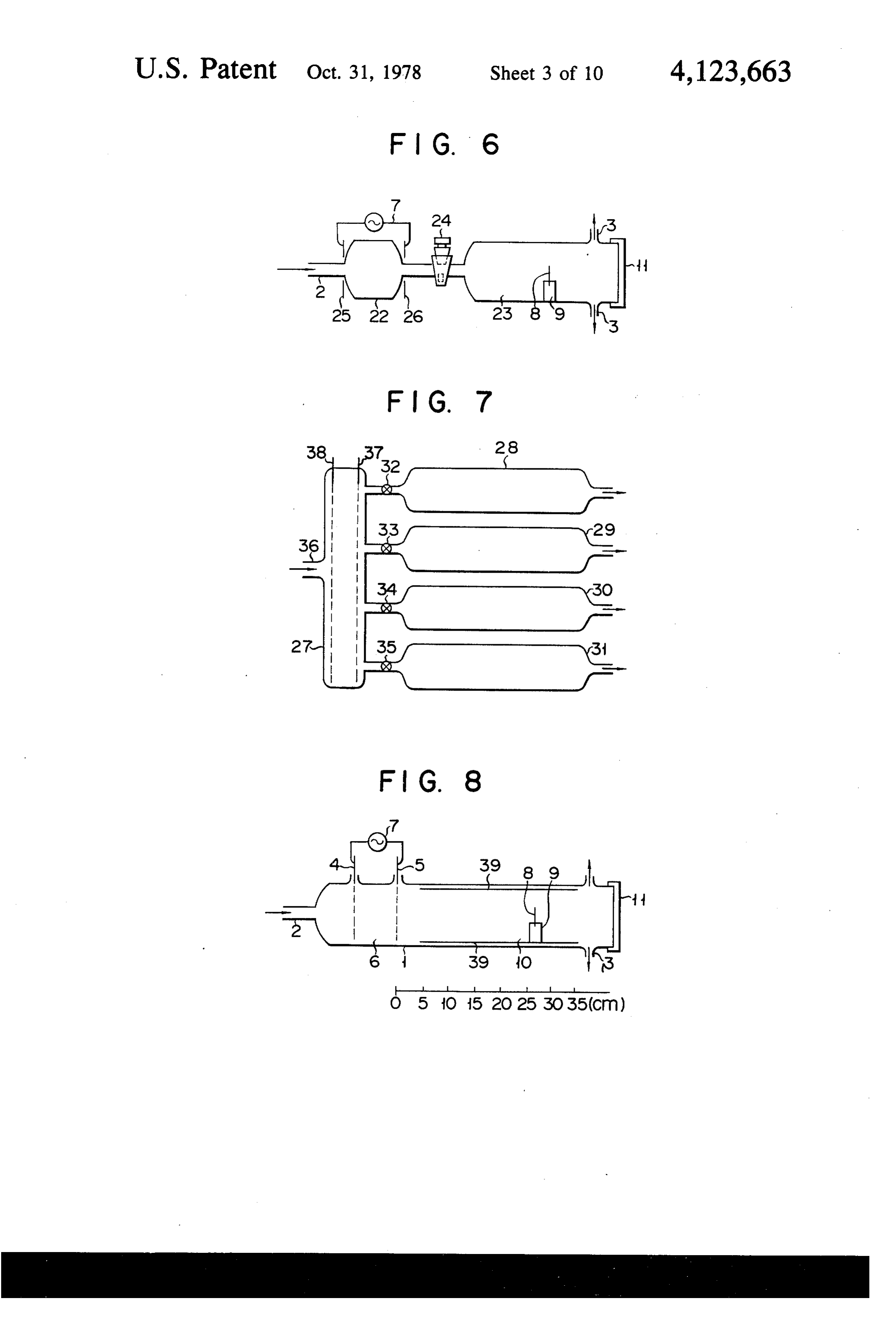
such as, for example, hydrofluoric acid are not pro FIG. 4 is a sectional view of the gas etching device duced, which improves the operational environment. according to another embodiment of the invention; However, what can be said commonly to the above 50 mentioned known apparatuses is that an etching gas anFIG. 5 is a sectional view showing a modification of etching gas-producing region of the gas etching producing region and a section for placing therein a device of the invention;
material to be etched are provided in the same place.
For this reason, said known apparatuses pose the fol theFIG. 6 is a sectional view of the gas etching device of invention wherein a cock is provided between the lowing problems. 55 etching gas-producing region and the reaction region; (1) Due to the radiant heat of the plasma and the actions of exciting light (especially, ultraviolet rays), theFIG. 7 is a sectional view of the gas etching device of invention having a number of reaction regions;
fluorine ion, etc. a photoresist used as a mask is deterio FIG. 8 is a sectional view of the gas etching device of rated and etched. the invention whose reaction region has an aluminum (2) Due to oxygen added to a CF, gas to an extent of made cylinder;
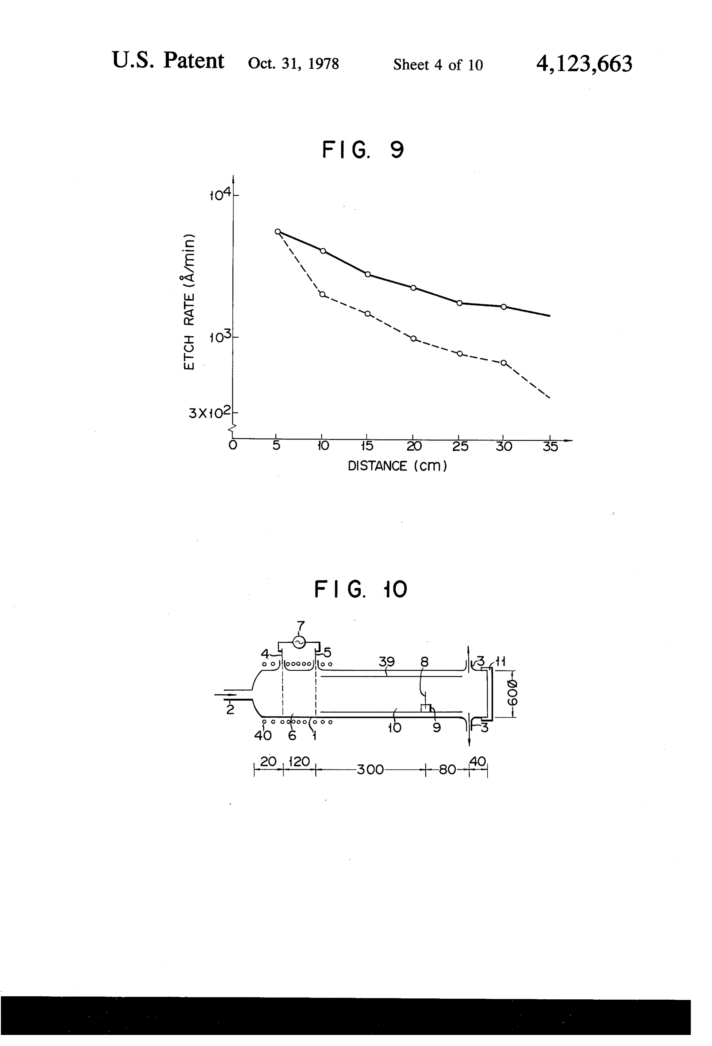
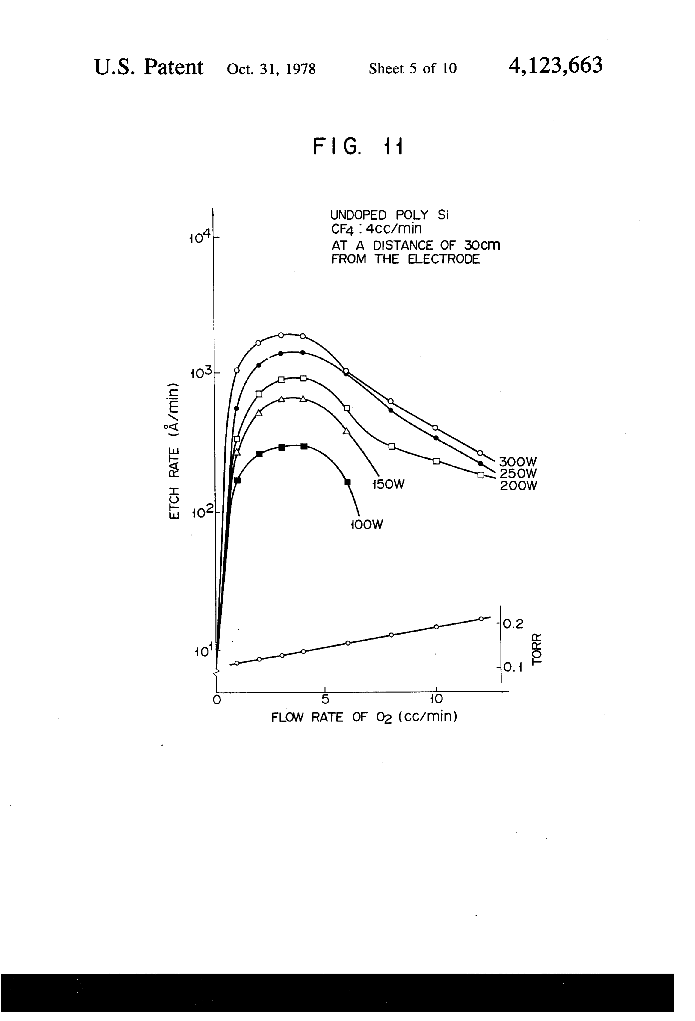
2 to 4% in order to increase the etching rate, the photo FIG. 9 graphically shows the results obtained by resist ashing proceeds. performing etching by the use of the device of FIG.8; (3) Due to the changed particles in the plasma the FIG. 10 is a sectional view of the gas etching device semiconductor element is damaged. of the invention whose etching gas-producing region is (4) Due to the actions of electric and magnetic fields 65 provided therearound with cooling pipes; positive and negative fluorine ions are ununiformly FIG. 11 graphically shows the results obtained by distributed, which causes the etching material or sample performing etching with the power varied, by the use of to be ununiformly etched. the device of FIG. 10;
Page 13
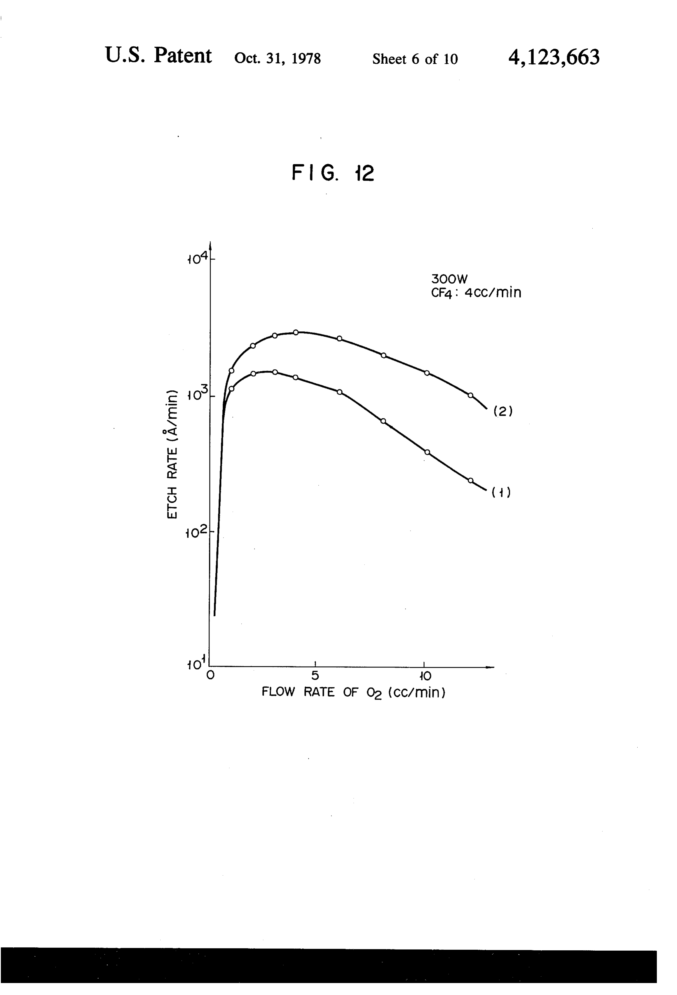
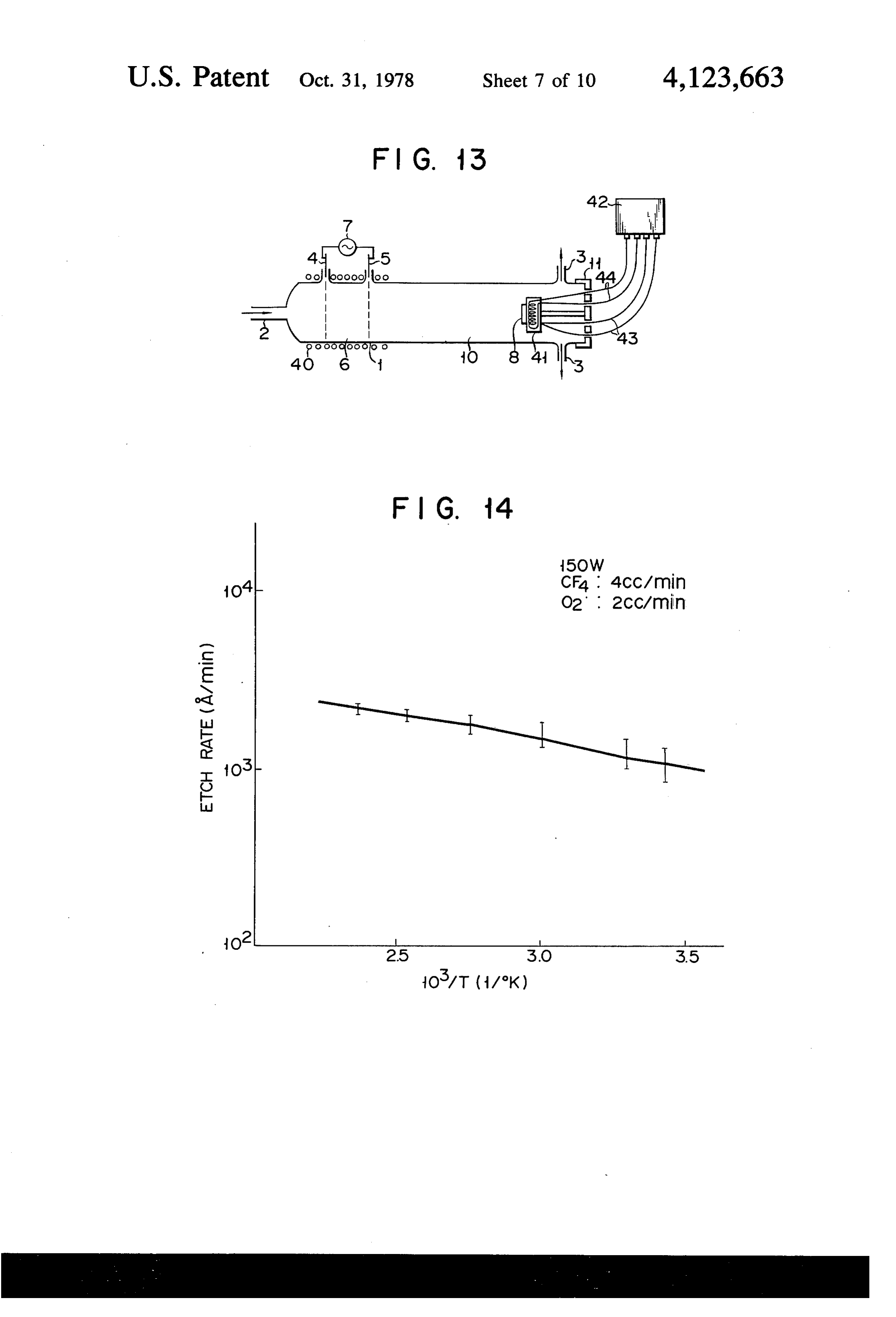
FIG, 12 graphically shows, while comparing, the the etching rate of the poly-Si in a leeward place at the results obtained by performing etching by the use of the same distance from the etching gas-producing region is device of FIG. 10 and a similar device with no cooling largely increased up to about 1500A/min. This is con 1pes; . .. . . sidered because the freon gas and the oxygen gas are p E. 13 is a sectional view of the gas etching device dissociated by applying a high power to the narrow of the invention provided with a heating plate for heat arranged paired electrodes to form an active species or ing the material to be etched; an etching gas having a very long life. FIG. 14 graphically shows the results obtained by As previously mentioned, the gas etching device of performing etching by the use of the device of FIG. 13; the invention has solved various problems by isolating FIG. 15 is a sectional view of a vertical type gas O the etching gas-producing region from the reaction etching device of the invention; region. Further, in this device, when the amount of gas FIG. 16 graphically shows the distribution of the containing oxygen atoms is set at at least 10% (by vol temperature of the material-placing section of the de ume) of the amount of gas containing fluorine atoms, vice of FIG. 15; the etching rate can be largely increased. Further, a FIG 17 is a sectional view of the gas etching device 15 decrease in the etching rate due to a rise in the tempera of the invention wherein the aluminum cylinder within ture of the etching gas-producing region can be pre the reaction region is connected to one of two electrode vented by cooling the etching gas-producing region. plates in the etching gas-producing region; Further, by heating the material to be etched, etching is FIG. 18 is a sectional view of the gas etching device uniformly achieved and simultaneously the etching rate of the invention wherein a cylindrical electrode is pro 20 is increased, so that the time required to carry out the vided outside the reaction region and part of the high manufacturing process can be shortened. Further, by frequency is applied to this electrode; providing a supplementarily exciting means in the reac FIG. 19 graphically shows the results obtained by tion region to bring the reaction region into a condition performing etching by the use of the device of FIG. 18; wherein it is being excited due to weak discharge, the FIG. 20 is a sectional view of the gas etching device 25 etching rate can be largely increased and even in the of the invention for etching a number of materials to be case where the distance between the etching gas-pro etched, wherein electrodes connected to a high fre ducing region and the material to be etched is great, a quency source are provided outside pipes for guiding an decay in the etching gas does not occur and therefore etching gas from the etching gas-producing region to the etching gas can be sent into a number of reaction the material to be etched; and 30 regions and therefore the device becomes easy to de FIG.21 is a sectional view of the gas etching device sign, because the etching gas-producing region and the of the invention provided with a microwave generating reaction region can be connected by a pipe which means as an exciting means. guides the etching gas.
.. DETAILED DESCRIPTION OF THE Hereinafter, embodiments of the invention are ex 35 plained by reference to the appended drawings.
FIG. 1 shows the outline of a gas etching device of
This invention is based on the discovery that when a the invention. A vacuum vessel 1 is a quartz tube having gas plasma is produced by introducing a freon gas and a diameter of, for example, 60 mm, and provided with a an oxygen gas into a vacuum vessel and applying a high gas inlet 2 and a gas outlet 3. A mixed gas of a gas frequency power to a pair of flat plate type electrodes containing fluorine atoms such as freon gas (CF) and a disposed within the vacuum vessel and discharging gas containing oxygen atoms such as oxygen gas is these electrodes, active species or an etching gas having introduced into the vessel from said gas inlet 2. As a very long life of several or more seconds is produced another gas-introducing method, it is possible to intro and, due to said active species, a poly-crystalline silicon duce only the freon gas from the gas inlet 2 and dispose poly-Si, etc. is sufficiently etched even in the place, 45 in advance a substance evolving the gas containing considerably distant from the plasma, where no exciting therein oxygen atoms such as an oxide or quartz glass in light exists. Conventionally, it is generally thought that the vacuum vessel 1.
under a degree of vacuum at which a gas plasma is The gas outlet 3 is connected to a vacuum pump (not produced the mean free path of a gas is on the order of shown), and by this pump the vessel interior is kept at a a few hundred millimeter at most; and the excited gas 50 vacuumized condition of, for example, 0.1 to 1 Torr. atoms and molecules' respectively collide with each The mixed gas introduced into the vacuum vessel 1 is other to be returned to their ground states. In the con supplied into an etching gas-producing region 6 formed ventional plasma-etching device wherein the freon gas between a pair of parallel plate electrodes 4 and 5. As is dissociated by discharge through applying an RF the pair of parallel plate electrodes 4 and 5 perpendicu (radio frequency) to the high frequency coil or con 55 larly to the gas-flow direction within the vessel 1, in denser type electrode which is disposed outside the comparison with the conventional plasma etching de vacuum vessel, therefore, a material such as poly-Siwas vice which is provided with coils or electrodes outsides not etched in a leeward place at a distance often centi of the vessel, power consumption in this device can be meters odd from the etching gas-producing region. It decreased. The parallel plate electrodes 4, 5 are consti has been found, however, that when, as in the device of 60 tuted by two parallel circular aluminum plates, the di the invention, the freon gas is dissociated and excited by ameter of each of which is 56 mm and which each have discharge through providing a pair of flat type elec a number of apertures each having a diameter of 5mm, trodes in the vacuum vessel and applying an RF and the distance between which is 12 cm. But the dis thereto, the poly-Si is etched in a leeward place at a tance between these paired electrodes and the diameter distance of ten centimeters odd from the etching gas 65 of said apertures do not particularly influence the action producing region though the etching rate of the poly-Si and effect of the invention, and it will serve the purpose is as low as about 2A/min, and that when an oxygen if only two plate electrodes having a number of aper gas equal in volume to the freon gas is added thereto, tures as gas-passageways are arranged in parallel. When
Page 14
a power having an RF (radio frequency) of 13.56MHz watch under illumination of natural light the condition is applied between the electrodes 4 and 5, discharge is in which the material 8 to be etched or sample is being effected in said mixed gas to produce a plasma com etched and, accordingly, the operation efficiency is posed of positive and negative ions, neutral atoms and remarkably increased.
molecles, of fluorine and oxygen. It is also possible to A gas etching shown in FIG. 4 is of the structure use a D.C. high voltage source or a microwave genera wherein the etching gas-producing region is sufficiently tor instead of the RF power souce, which would be able spaced apart from the reaction region, and, by being so to further increase the etching rate. The use of the mi constructed, capable of achieving a much better etch crowave generator would offer an advantage that the ing. A tube 14 each having a gas inlet 13 formed therin electrodes disposed within the vacuum vessel become 10 are attached to the vacuum vessel 1 formed of, for ex unnecessary. ample, a quartz tube. The tube 14 are each made of The etching gas thus produced is then guided to a aluminum and concurrently act as a pair of electrodes reaction region 10 spaced apart from the etching gas and are so provided as to seal the vacuum vessel 1 and producing region 6. Within the reaction region 10, a further are fitted with cylindrical alumina tubes 15 each material to be etched 8 is disposed on a support member 15 having a length of about 10 cm. The gas introduced 9 at a distance of, for example, 30 cm from the electrode from the gas inlet 13 (for example, a mixed gas of CF 5. Introduction or withdrawal of the material 8 can be and O2) is passed through regions each defined by the effected by mounting or dismounting a covering 11 outer wall of the alumina tube 15 and the inner wall of provided for the vacuum vessel 1. the vacuum vessel. The electrodes made by a doughnut FIG. 2 graphically shows the results obtained by 20 like perforated aluminum plate 16 are provided in the etching a poly-Si film at a growing temperature of 680 neighbourhoods of the exits of these regions. An RF C., undoped using the freon gas (CF) and oxygen gas power 7 is applied between the electrodes and a corre (O) as an etching gas and employing the above-men sponding the tube. As a result, said mixed gas is dissoci tioned gas etching device of the invention. In FIG. 2, ated to produce an etching gas. Arrows of FIG. 4 indi the flow rate of O, (cc/min.) is plotted on the abscissa 25 cate the flow direction of the etching gas. The covering and the etching rate of the poly-Si film (A/min.) is 11 is made of quartz. Further, the outer wall 17 of the plotted on the ordinate. At that time, the flow rate of etching gas-producing region is made of alumina, and CF was 4 cc/min., the RF power was 300W, and the plays the role of preventing the quartz from being cor exhaust rate by the vacuum pump was 300 l/min. Ac roded due to the action of the etching gas. cording to the conventional method, the ratio of the 30 FIG. 5 shows a modified structure of the etching flow rate of O. to that of CF4 was made as extremely gas-producing region. The mixed gas of freon gas and low as 2 to 4%, but as apparent from FIG. 2, in the case oxygen gas is introduced from a gas inlet 19 formed in of employing the device of the invention, it is seen that a peripheral portion of a disc plate-like etching gas-pro said ratio can be effectively set at a value much greater ducing region 18 into this region 18. Within the etching than said value of 2 to 4%, for example, more than 10%. 35 gas-producing region 18 two pairs of perforated alumi As a result, since, according to the invention, the adding num electrodes 20, 21 each having a number of apera amount of O can be increased, flow rate control be tures are concentrically provided in an insulated and comes extremely easy whereas since, according to the sealed manner. An RF power is applied between these conventional method, the adding amount of O2 is small, electrodes to produce an etching gas. it is difficult to control exactly flow rate of O and the A gas etching device shown in FIG. 6 is of the struc etching rate. ture wherein a cock 24 is provided between an etching Further, as apparent from FIG. 2, it is seen that as the gas-producing region 22 constituting the vacuum vessel introducing amount of O2 is decreased, the etching rate and a reaction region 23. The cock 24 is for the purpose is decreased rapidly. In contrast, when the introducing of adjusting the degree of vacuum of the etching gas amount of O2 was increased, a decrease in the etching 45 producing region 22. A pair of electrodes 25, 26 are pro rate was not sharp though the degree of vacuum was vided outside the etching gas-producing region 22, and decreased. Further, where the exhaust rate by the vac an RF power is applied between these electordes. The uum pump was set at 300 l/min., a decrease in the etch mixed gas of freon gas and oxygen gas introduced from ingrate due to an increase or decrease in the introduc the gas inlet 2 into the etching gas-producing region 22 ing amount of oxygen gas occurred only to a small 50 is excited by application of an RF power to produce an extent and the larger the exhaust rate, the faster the etching gas. This etching gas is passed through a gas etching rate, for the amount of the etching gas per min outlet of the etching gas-producing region and the cock utes produces the more. 24 and is supplied from a gas inlet of the reaction region Further, with respect to the position of the material 23 into the region 23 and due to the action of this etch to be etched, when it was placed at a distance of not less 55 ing gas the sample 8 is etched. Where the cock 24 is than 10 cm from the etching gas-producing region, a closed, the etching gas is confined in the etching gas preferable result was obtained. Further, when the input producing region 22, and etching can be performed by power was increased, the etching rate was raised. opening the cock 24 as required. Further, the plasma Hereinafter, various modifications of the gas etching producing requirements and etching reaction conditions device of the invention are shown. 60 can be made optimum by adjusting the degree of vac A gas etching device shown in FIG. 3 is of the struc uum in which the cock 24 is regulated. ture wherein the etching gas-producing region 6 of the FIG. 7 shows a gas etching device of the structure device shown in FIG. 1 is bent with respect to the reac wherein the vacuum vessel is composed of an etching tion region 10. In this device, the whole of the etching gas-producing region 27 and a plurality of reaction gas-producing region 6 is surrounded by a shielding 65 regions 28, 29, 30, and 31. Valves 32, 33, 34 and 35 are member 12. By so doing, the ultraviolet rays radiated provided between the etching gas-producing region 29 from the etching gas-producing region 6 are completely and reaction regions 28, 29, 30 and 31. Through opening shielded with the result that it becomes possible to or closing these valves, the reaction regions can be
Page 15
opened or closed, and adjusted in terms of pressure. The temperature rising, the etching rate of silicon dixoide mixed gas of freon gas and oxygen gas introduced from (SiO2) become high.
a gas inlet 36 into the etching gas-producing region 27 is As the etching gas produced is consumed to etch the excited by applying an RF power between a pair of wall of the quartz tube, the etching rate of materials to electrodes 37, 38 provided within the etching gas-pro 5 be etched decreases. Accordingly, that temperature rise ducing region 27, to produce an etching gas. This etch is prevented by cooling the wall of the etching gas-pro ing gas is passed through the valves 32, 33, 34 and 35 to ducing region by the cooling pipes 40. This cooling enter the reaction regions 28, 29, 30 and 31, and thus the effect is shown in FIG. 12. FIG. 12 graphically shows material is etched. By maintaining the valve to be closed the etching rate of a poly-Siobtained when cooling is and then recovering the atmospheric pressure in the O not performed (1) and when cooling is performed (2). reaction regions, the materials in the regions can be From this graphical diagram it is seen that the etching individually replaced for each reaction region. rate is made two-fold by cooling the etching gas-pro FIG. 8 shows a gas etching device of the structure ducing region.
wherein an aluminum-made cylinder 39 is inserted into FIG. 13 shows a gas etching device of the structure the reaction region 10 of the gas etching device shown 15 wherein a heating means for heating the material 8 to be in FIG. 1. In this device, the etching rate was increased etched such as a heating plate 41 is provided within the up to twice or more the etching rate attainable where reaction region 10. The temperature of the material 8 is said cylinder 39 is not inserted. As an example, the controlled from outside by a controller 42, 43 denotes results obtained by etching a poly-Si using this device thermocouples and 44 wiring for said heating means. and that device with no such cylinder which is shown in 20 FIG. 14 graphically shows the etching rate when, in the FIG. 1 is presented in FIG. 9. On the ordinate the etch case of etching a poly-Si using the gas etching device ing rate is plotted and on the abscissa the distance be shown in FIG. 13, the temperature of the material 8 is tween the electrode 5 and the material 8 is plotted. varied utilizing the heating plate 41. In FIG. 14, 1/TX Etching was carried out under the condition wherein 10 (where T is absolute temperature) is plotted on the the input power is 300W; the flow rate of CF4 is 4 25 abscissa, and the vertical lines each represent the degree cc/min, and the flow rate of Ois 4 cc/min. In FIG. 9, of uniformity in the etching rate. From this graphic the case where etching is performed using the device diagram it is seen that as the material temperature is with said cylinder is indicated by a solid line and the increased, the length of the vertical lines representing case where etching is performed using the device with the degree of uniformity in the etching is remarkably no such cylinder by a broken line. As apparent from 30 decreased, that is, the uniformity degree in the etching FIG. 9, the etching rate is remarkably increased by becomes smaller.
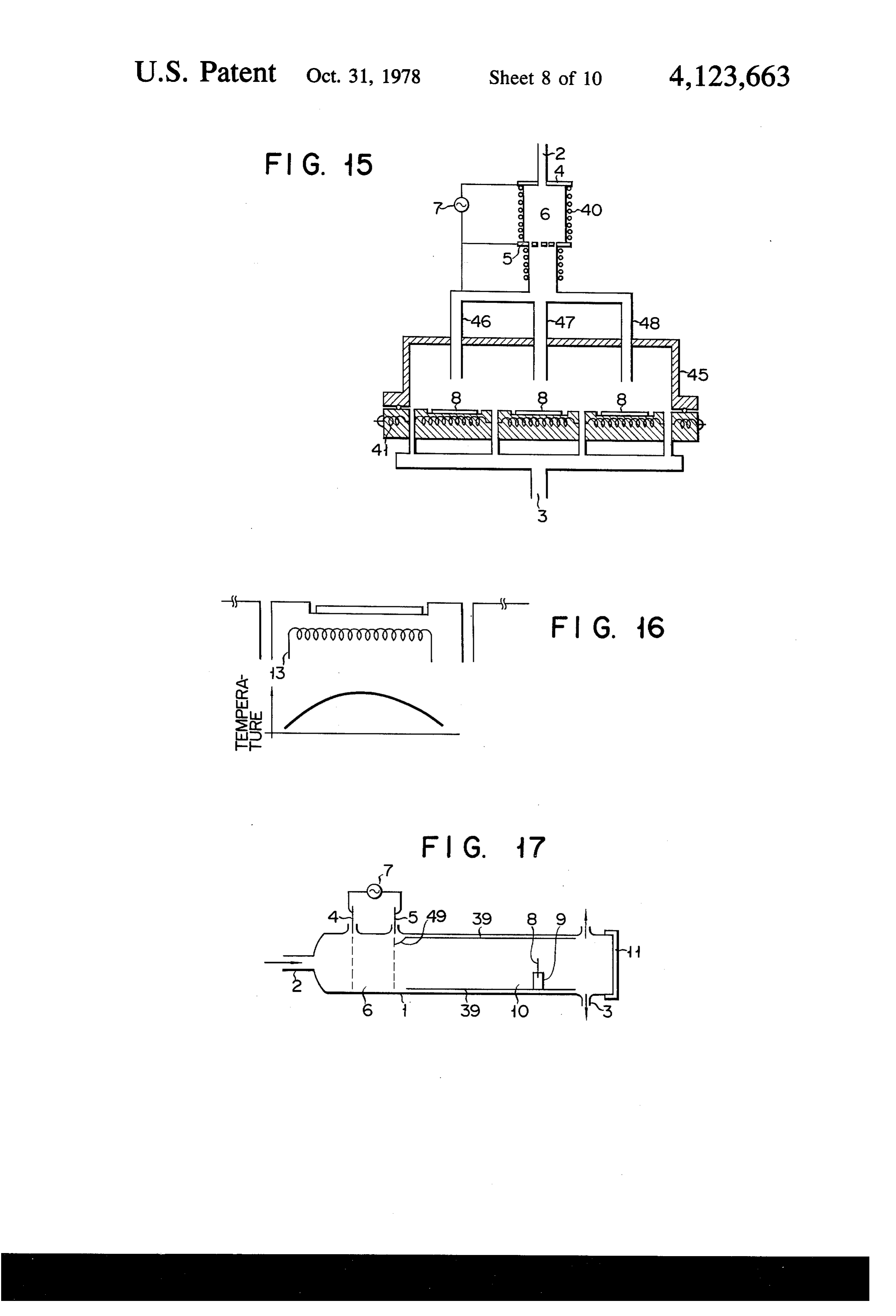
disposing the aluminum-made cylinder in the reaction FIG. 15 shows a gas etching device for batch-proc region. essing a large number of silicon wafers. Any of the FIG. 10 shows a gas etching device of the structure above-mentioned gas etching devices is of the horizon wherein a cooling means such as cooling pipes is pro 35 tal type. When materials are etched in any of the above vided outside the etching gas-producing region 6 of the mentioned gas etching device, the materials to be gas etching device shown in FIG. 8. FIG. 11 graphi etched is set at parallely toward a gas flow. In this type cally shows the etching rate when a poly-Si is etched of gas etching device, the etching gas is first consumed using this device; and the flow rate of O, is varied under from the windward side of the material to be etched and the condition wherein the flow rate of CF is set to 4 40 then etching proceeds toward the leeward side, and cc/min. This graphic diagram shows also the relation therefore, when the etching operation is completed, a ship between the flow rate of O, and the etching rate, portion of the material 8 at the windward side is etched established when the power is varied. From FIG. 11 it superfluously. In order to eliminate such drawback, the is seen that even when a plasma is produced with a low device shown in FIG. 15 is constructed into a vertical power of 100W or 150W, a high etching rate is obtained 45 type. In this device, the etching gas is supplied to the with a mixing rates of CF4 to O, of about 4:1 to 6, that material through gas-introducing pipes 46, 47 and 48 is, a sufficiently large amount of etching gas is pro constituting the inlet portions of a reaction region 45. duced. Further, it is also seen that as the applied power Further, in this device, the etching gas-producing re is increased, the maximum etching rate is shifted in a gion is cooled and the material to be etched is heated, direction in which the flow rate of O is increased, and 50 similarly to the device shown in FIG. 13. As a result, simultaneously that a high etching rate is obtained over etching was uniformly achieved at a high etching rate. a wide range of flow rate of O. That is, when a large Further, in this device, etching is likely to be performed amount of power is applied, the amount of O, can be from the peripheral portion toward the central portion, chosen over a wide range. For this reason, even when of the material to be etched. Therefore, by constructing the flow rate of O is on the order of 0.5 cc/min. based 55 the heater so that each support member is more heated on a CF, flow rate of 4 cc/min., that is, if only the at its central portion than at its peripheral portion, etch amount of Oin the mixed gas is about 10% or more of ing can be conducted more uniformly.
the amount of CF4, an etching gas is easily produced. Next, a gas etching device of the type wherein, in the Further, in FIG. 11, the variation in the vacuum degree aforesaid gas etching devices of the invention, a supple is also shown, and it is also seen that the range of this 60 mentarily exciting means is provided within their reac variation is as very narrow as 0.1 to 0.2 Torr. tion region is described.
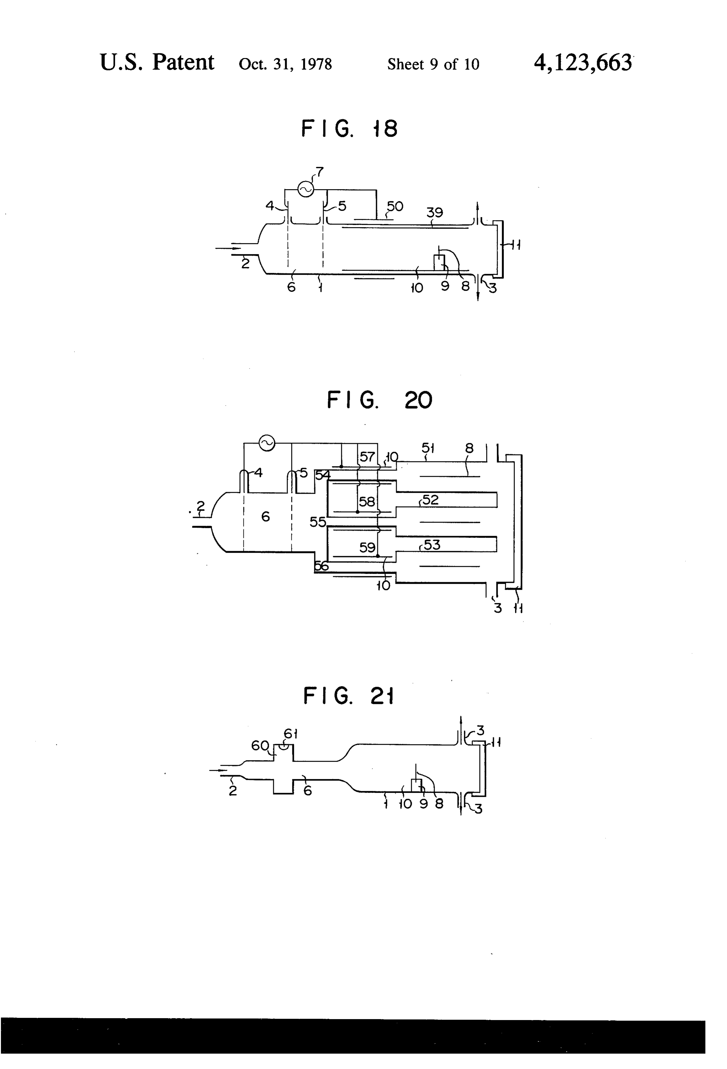
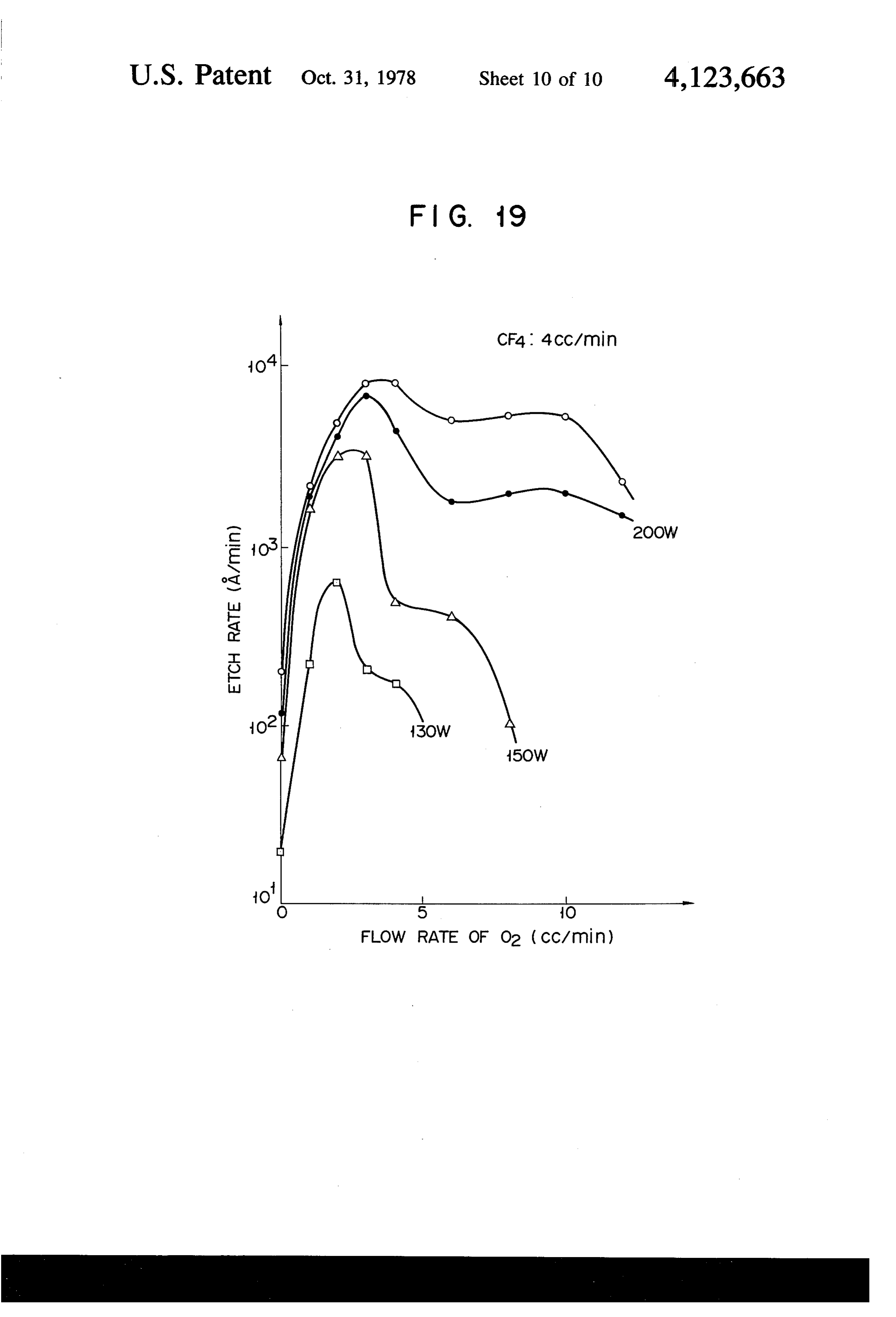
The reasons why, in the gas etching device shown in FIG. 17 shows a gas etching device of the structure FIG. 10, the cooling pipes 40 are provided outside the wherein, in the gas etching device shown in FIG. 8, an etching gas-producing region 6 are as follows. As the aluminum-made cylinder 39 inserted into its reaction period of time during which the etching operation is 65 region 10 is connected by a conductor 49 to one of the carried out becomes long, the temperature of the etch pair of electrodes of the etching gas-producing region. ing gas-producing region is increased as a matter of Since, in this type of device, the reaction region interior course. Generally in the plasma etching device, as the is kept in a state excited due to weak discharge, the
Page 16
etching gas is not decayed. Therefore, when etching material to be etched having a diameter of 50 to 70 mm was carried out using this device, there was obtained an is set. If, therefore, an L band frequency (1 to 2 GHz) is etching rate which is as extremely high as four times the used, an etching gas-producing region having a larger etching rate obtained in the case of using a conventional diameter can be used.
device as shown in FIG. 19. Even a tungsten silicide, What is claimed is:
for example, which was conventionally difficult to etch 1. A gas etching device for plasma-free etching of a has become possible with this device. Further, it has material comprising:
become possible with this device to perform etching a vacuum vessel having an etching gas-producing without deteriorating a photoresist due to, for example, region and a reaction region spaced therefrom, the ultraviolet rays as in the conventional case. A gas etch 10 reaction region having a defined location at which ing device shown in FIG. 18 is of the structure wherein the etching gas reacts with the material, a cylindrical electrode 50 is provided outside the reac means to introduce gases into said etching gas-pro tion region 10 and, by applying part of high frequency ducing region, to this electrode, the aluminum-made cylinder 39 within a high frequency discharging means positioned with the reaction region 10 is high frequency-coupled to that 15 respect to said etching gas-producing region to electrode 50. Also in the case where etching was per activate said gases to form a long-life active species formed using said device, such results as shown in FIG. as the etching gas, 19 were obtained. pipe means interposed between the etching gas pro Such supplementarily exciting means provided for ducing region and the reaction region, the reaction region is effective particularly when the 20 means to withdraw the etching gas from the etching distance between the etching gas-producing region and gas-producing region to the reaction region the material to be etched is large as in the following through the pipe means, the reaction region being example. A gas etching device shown in FIG. 20 is at spaced from said etching gas-producing region a the structure wherein a number of reaction regions are distance fixed to provide electrical isolation of said so provided as to etch a number of materials to be 25 defined location from electric fields in the etching etched. Since, in this type of device, the distance over gas-producing region, whereby the etching gas at which the etching gas is supplied to the materials is said defined location is plasma-free and remains large, the etching gas is decayed to cause a decrease in sufficiently activated to etch the material at said the etching rate. In order to prevent the decay of the defined location.
etching gas, aluminum-made cylinder electrodes 57, 58 30 2. A gas etching device for etching a material accord and 59 are provided outside those guide pipes 54, 55 and ing to claim 1 wherein the high frequency discharging 56 constituting the respective inlet portions of the reac means is positioned outside the vacuum vessel, and tion regions 51, 52 and 53 which are intended to guide further comprising:
the etching gas to the material to be etched from the means interposed between the etching gas-producing etching gas-producing region and are connected to a 35 region and the reaction region to control the rate of high frequency power source of the etching gas-pro flow of the etching gas from the etching gas-pro ducing region thereby to bring the interiors of said ducing region into the reaction region. guide pipes 54, 55 and 56 to a state excited due to weak 3. A gas etching device for etching a material accord discharge. Thus, even when the etching gas is passed ing to claim 2 further comprising:
through a passageway having a sufficiently large 40 cooling means positioned outside the vacuum vessel length, it is not decayed and as a result the etching rate to cool said etching gas-producing region. can be maintained high. Further, by providing a supple 4. A gas producing device for etching a material mentarily exciting means similar to said aluminum-made according to claim 1 wherein the vacuum vessel defines cylinder electrodes for the etching gas-introducing a bend between the etching gas-producing region and pipes 46, 47 and 48 of the vertical type gas etching 45 the reaction region.
device shown in FIG. 15, a number of materials can be 5. A gas producing device for etching a material well etched. according to claim 4 wherein said bend is substantially The foregoing description referred to the gas etching a right-angle bend.
device so designed as to produce an etching gas by 6. A gas etching device according to claim 1 wherein exciting O2 and CF4 through applying a high frequency. 50 the reaction region includes support means to support But it is also possible to produce an etching gas by the material acted upon such that the etching gas from exciting those gases through applying a microwave (e.g. the etching gas-producing region flows perpendicularly 2.4 GHz). In this case, a further increasing amount of to the plane of said support means.
etching gas is produced and therefore the etching gas 7. A gas producing device for etching a material can be carried farther. In a gas etching device shown in 55 according to claim 1 wherein said high frequency dis FIG. 21, the etching gas-producing region 6 has only to charging means comprises a pair of apertured elec be designed to penetrate through a rectangular wave trodes connected to a high frequency power source and guide 60, which offers an advantage that the paired disposed within said vacuum vessel perpendicularly to electrodes within the vacuum vessel are unnecessary. the flow direction of said gases.
The mixed gas introduced is excited by a microwave 60 8. A gas etching device for etching a material accord generated from a microwave generator 61 provided for ing to claim 1 further comprising:
the wave guide 60 thus to become an etching gas. The cooling means positioned outside the vacuum vessel reason why the inner diameter of the etching gas-pro to cool said etching gas-producing region. ducing region 6 is made smaller than that of the reaction 9. A gas etching device for etching a material accord region 10 is that since, in FIG. 21, the use of an S band 65 ing to claim 1 wherein said gases include a mixture of an frequency (2 to 4 GHz) is pressupposed, the region 6 oxygen gas and freon gas, the amount of the oxygen gas can not but become smaller in diameter as a matter of being at least 10% by volume of the amount of the freon course, as compared with the region 10 within which a gas.
Page 17
10. An etching device for etching a material as recited in claim 1, wherein the pipe means comprises a in claim 1, further comprising means to branch the branched structure to introduce the etching gas to a etching gas at the defined location. plurality of reaction regions. 11. An etching device for etching a material as recited is is
Provenance
- Collection
- Cited prior art
- Original PDF
- patentimages.storage.googleapis.com →
- Filed
- 1976-01-08
- Pages
- 17
- Method
- pdftotext (the PDF's own text layer) + pdftoppm 300dpi page scans
- Source
- Google Patents bibliographic record
- Granted
- 1978-10-31
- Inventors
- Yasuhiro Horiike; Tokyo Shibaura Electric Co Ltd
- Transcribed from
- patentimages.storage.googleapis.com →