patent · US4520862
Energy storage apparatus
4 June 1985
Page 1 — bibliographic record
United States Patent 19 (11) Patent Number: 4,520,862 Helmbold 45) Date of Patent: Jun. 4, 1985 54 ENERGY STORAGE APPARATUS FOREIGN PATENT DOCUMENTS 76) Inventor: Walter Helmbold, Vorder Hurth 31, 6041.96 4/1978 U.S.S.R............................... 219/378 5902 Unglinghausen, Fed. Rep. of
Germany Primary Examiner-Albert W. Davis, Jr.
21 Appl. No.: 465,068 Attorney, Agent, or Firm-Sughrue, Mion, Zinn, Macpeak and Seas 22 Filed: Feb. 8, 1983 57 ABSTRACT (30) Foreign Application Priority Data There is disclosed storage apparatus for storage of en Feb. 11, 1982 IDE) Fed. Rep. of Germany ....... 3204849 ergy in the form of heat or cold, preferably over a pro Mar. 20, 1982 (DE) Fed. Rep. of Germany ....... 320370 longed storage period. The apparatus comprises a con tainer enclosing an energy storage Zone and an insulat (51 Int. Cl. .............................................. F28D 17/02 ing zone around the storage zone. The storage zone is 52 U.S. C. ...................................... 165/10; 165/135; filled with a mass of heatable or coolable storage mate 219/378; 219/472; 219/530; 219/531 rial forming a storage core, and the insulating zone with 58) Field of Search ........................... 165/10, 135, 96; a porous mass of granular or fibrous material forming a 219/472, 378,530, 531 thermal insulating layer. Energy can be supplied to the 56) References Cited storage core by, for example, a solar-powered electrical resistance heater and extracted from the core at a de
2,083,732 6/1937 Moore et al. ....................... 219/472 lating effect of the insulating layer is enhanced, particu 3,381,113 4/1968 Jacques et al. ...................... 219/378 larly from the viewpoint of long-term energy storage, 3,450,196 6/1969 Bauer .......... ... ... 219/378 by creation of a vacuum in the cellular structure of the 3,722,445 3/1973 Karig et al. ........................... 165/10 insulating layer.
3,773,031 11/1973 Laing et al. ........................... 165/10 3,823,305 7/1974 Schroder ............................... 165/96 16 Claims, 6 Drawing Figures
Page 2
Drawing sheet — no readable text.
Page 3
Drawing sheet — no readable text.
Page 4
Drawing sheet — no readable text.
Page 5
ENERGY STORAGE APPARATUS SUMMARY OF THE INVENTION
According to the invention there is provided storage
BACKGROUND OF THE INVENTION apparatus for storage of energy in the form of heat or The present invention relates to storage apparatus for cold over a selectably prolonged storage period. The the storage of energy in the form of heator cold, prefer apparatus comprises container means which forms an ably over a long storage period. external enclosure for an energy storage zone and for an For the supply of the population with power and insulating zone surrounding the storage zone. Present in heat, it is expected that increasing use will be made of 10 the storage Zone is a mass of heatable or coolable stor age material, which forms an energy storage core, while solar energy in the future, as direct utilization of solar present in the insulating zone is an insulating porous energy is possible without environmental side effects. mass of granular or fibrous material, which provides an For this reason, use of the photo-voltaic solar cell is insulating layer between the storage core and the con intensively investigated on a world-wide basis, as it permits sunlight to be directly converted into electricity 15 tainer means. Means are provided for heating or cooling the storage material to effect corresponding energy at an efficiency up to a maximum of 25%. storage in the core and means are also provided for Electrical current is a high grade form of energy. extraction
Amongst other things, current can be used to heat suit ing effect ofofthe stored energy from the core. The insulat insulating layer is increased well above able storage masses to high temperatures. If consider the insulating levels of known insulating arrangements ation is taken of the fact that half the population of, for by creation in the insulating zone, thus in the porous
example, the Federal Republic of Germany lives in mass of granular or fibrous material, of a pressure below single-family or two-family houses of which the roofs, atmospheric pressure.
according to position and orientation, are radiated by In the absence of any pressure barrier between the solar energy equal to between four and five times the 25 insulating and storage zones, the below-atmospheric winter heating requirement of such houses, then it pressure may also be created in the storage zone. Alter would clearly be advantageous to provide for heating of natively, a pressure barrier may be provided between a store to a high temperature with solar cell current and the two zones to confine the below-atmospheric pres to extract the heat from the store at times when heating sure to the insulating zone.
is required. As solar energy radiation is at its highest in The container means may consist wholly or partially summer and the greatest requirement for heating occurs 30 of an elastic or plastic material, which during the evacu in winter, utilization of solar energy necessitates a dura ation of the insulating layer transmits the external atmo ble long term heat store which can store the heat sup spheric pressure to the insulating mass so as to effect a plied in the summer without substantial heat loss before pressure equalisation between the external pressure and winter and which permits a simple form of heat extrac 35 the insulating mass. This measure may enable avoidance tion. of any difficulties which might arise when the insulating Stores are known for the storage of heat or cold with layer of a container means of relatively large area is an external container, an electrically, chemically or disposed under vacuum and must withstand the external thermally heatable or coolable storage mass and an pressure.
insulating layer arranged between the external con 40 Other objects and advantages of the present invention tainer and storage mass. Practice has shown, however, will be apparent from the following detailed description that a heat store of that kind with an insulating layer of of preferred embodiments and from the appended natural or synthetic insulating material, for example claims and drawings, which are described briefly here polyurethane, is not capable of providing adequate insu inbelow:
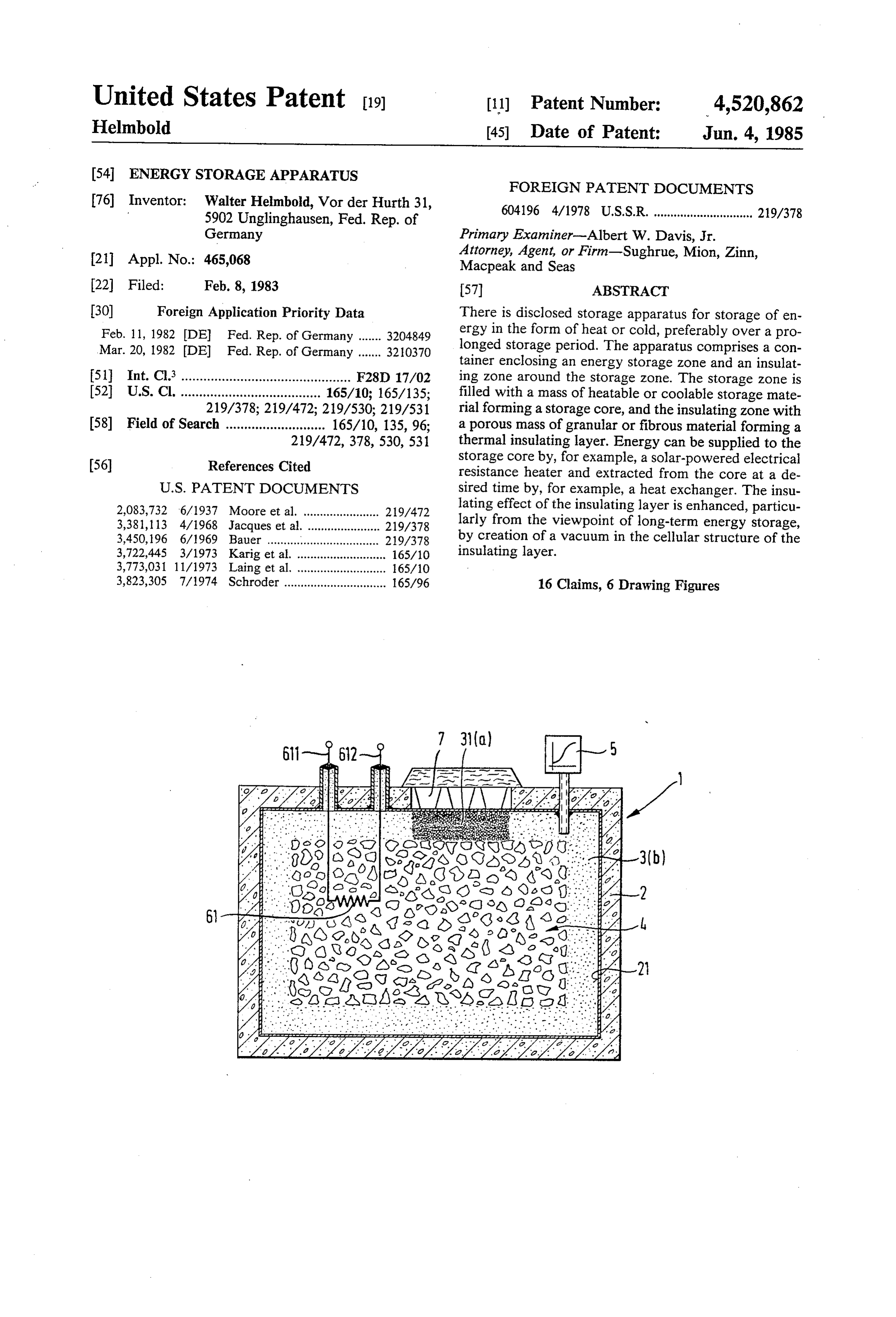
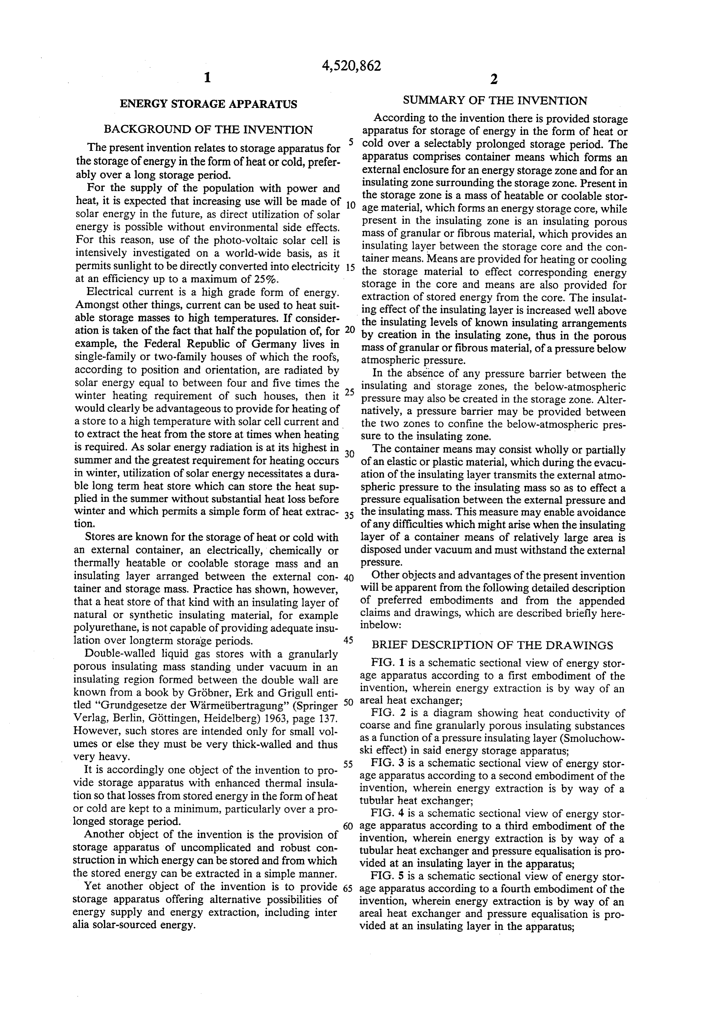
lation over longterm storage periods. 45 BRIEF DESCRIPTION OF THE DRAWINGS Double-walled liquid gas stores with a granularly porous insulating mass standing under vacuum in an FIG. 1 is a schematic sectional view of energy stor insulating region formed between the double wall are age apparatus according to a first embodiment of the known from a book by Gröbner, Erk and Grigull enti 50 invention, wherein energy extraction is by way of an tled "Grundgesetze der Wärmetibertragung' (Springer areal heat exchanger;
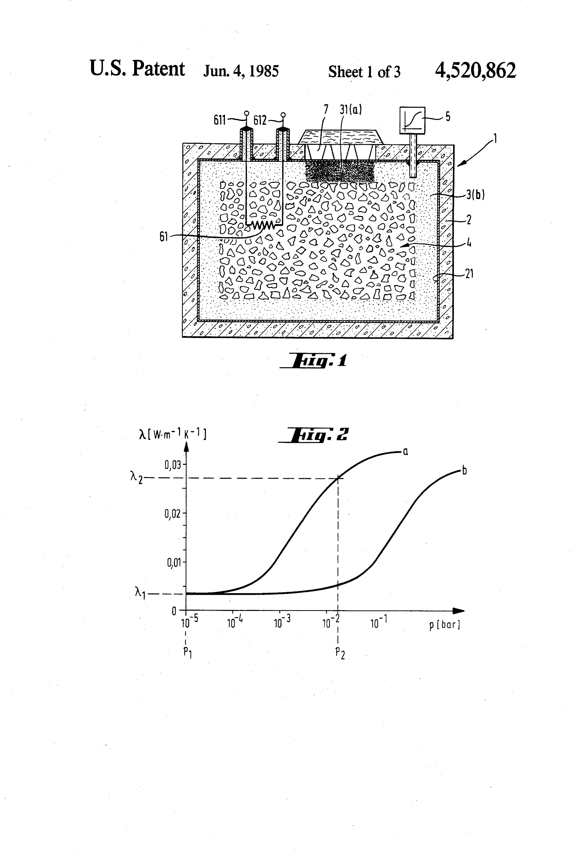
FIG. 2 is a diagram showing heat conductivity of
Verlag, Berlin, Göttingen, Heidelberg) 1963, page 137. coarse and fine granularly porous insulating substances However, such stores are intended only for small vol umes or else they must be very thick-walled and thus as a function of a pressure insulating layer (Smoluchow ski effect) in said energy storage apparatus;
very heavy.
It is accordingly one object of the invention to pro ageFIG.
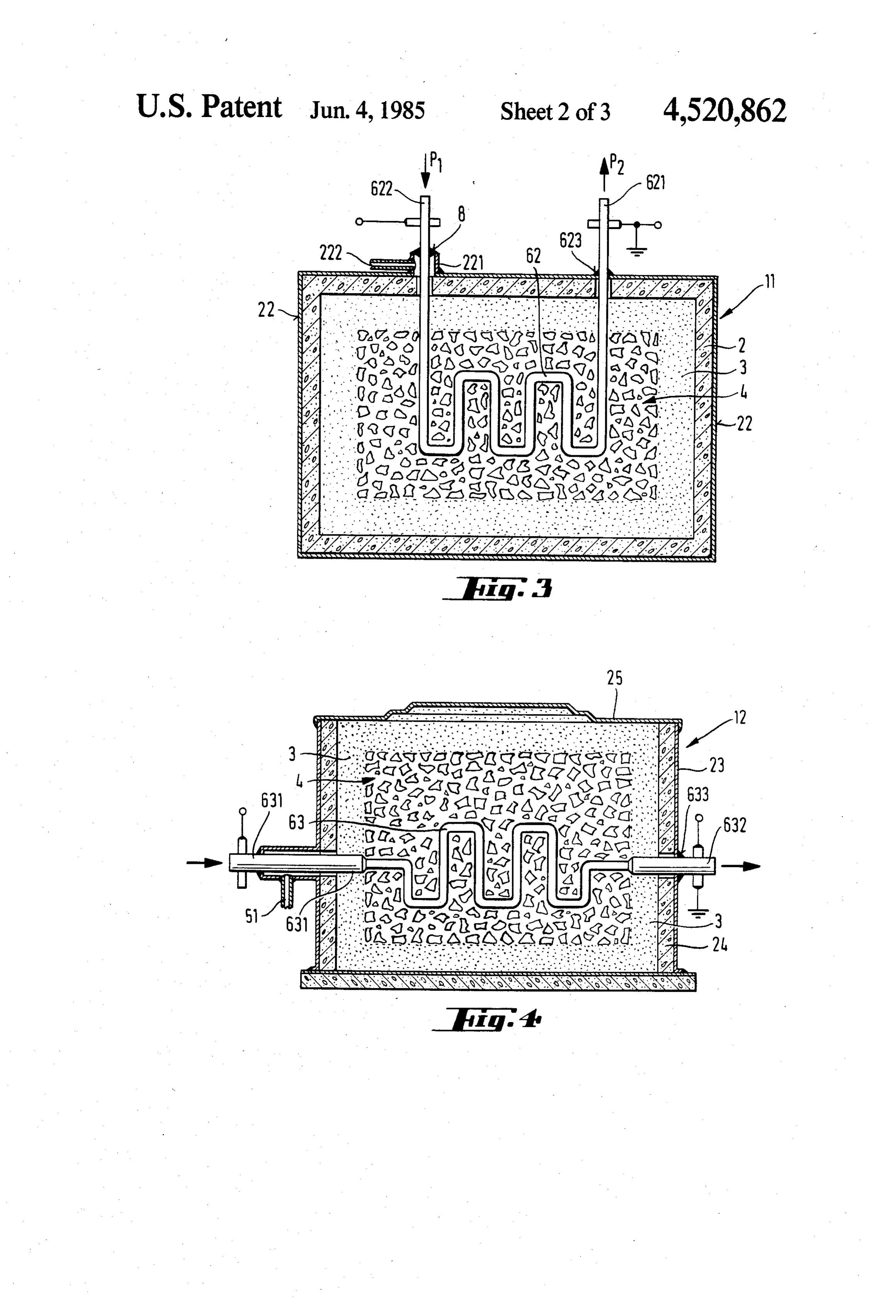
55 3 is a schematic sectional view of energy stor apparatus according to a second embodiment of the vide storage apparatus with enhanced thermal insula invention, wherein energy extraction is by way of a tion so that losses from stored energy in the form of heat tubular heat exchanger;
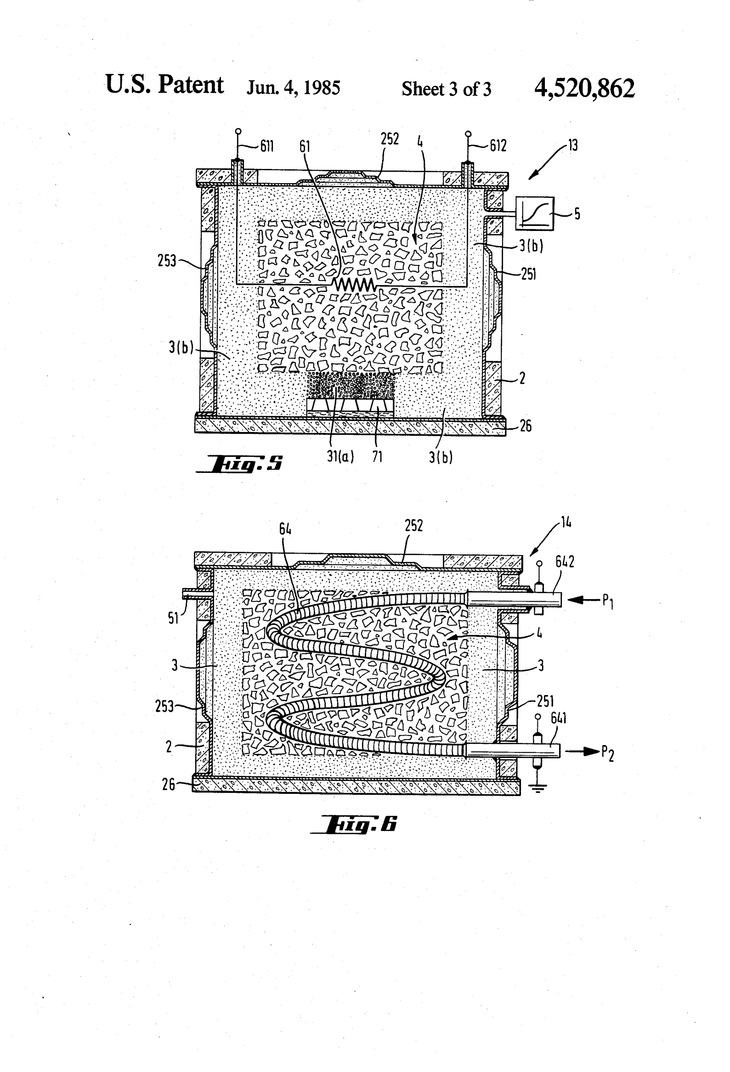
or cold are kept to a minimum, particularly over a pro FIG. 4 is a schematic sectional view of energy stor longed storage period. 60 age apparatus according to a third embodiment of the Another object of the invention is the provision of invention, wherein energy extraction is by way of a storage apparatus of uncomplicated and robust con tubular heat exchanger and pressure equalisation is pro struction in which energy can be stored and from which vided at an insulating layer in the apparatus; the stored energy can be extracted in a simple manner. FIG. 5 is a schematic sectional view of energy stor Yet another object of the invention is to provide 65 age apparatus according to a fourth embodiment of the storage apparatus offering alternative possibilities of invention, wherein energy extraction is by way of an energy supply and energy extraction, including inter areal heat exchanger and pressure equalisation is pro alia solar-sourced energy. vided at an insulating layer in the apparatus;
Page 6
FIG. 6 is a schematic sectiona view of energy storage flecting material, for example, magnesium oxide. The apparatus according to a fifth embodiment of the inven known insulating mass "MINILEIT" ("MINILEIT" is tion, wherein energy extraction is by way of a ribbed a Trade Mark of the firm Grinzweig & Hartmann, tube heat exchanger and pressure equalisation is pro Ludwigshafen, Federal Republic of Germany), contains vided at an insulating layer in the apparatus. an infrared reflecting powder. FIG. 1 shows heat storage apparatus comprising an If normal air pressure were to prevail in the insulating external container 2, an insulating layer 3 and a storage layer, then the afore-described proportions of point-to core 4. The container 2 consists of prefabricated con point conduction, heat radiation and reciprocal effect crete parts and has high grade steel plates 21 at its inside between wall surface, the steel plates 21 providing a vacuum 10 hidden byradiation and heat conduction are completely tight enclosure. Basalt chippings can be used as a stor the air is removed conduction the heat of the air. If, however, age mass in the storage core 4. The core 4 can be heated vacuum pump 5, thenfrom the insulating layer 3 by the the Smoluchowski effect applies.
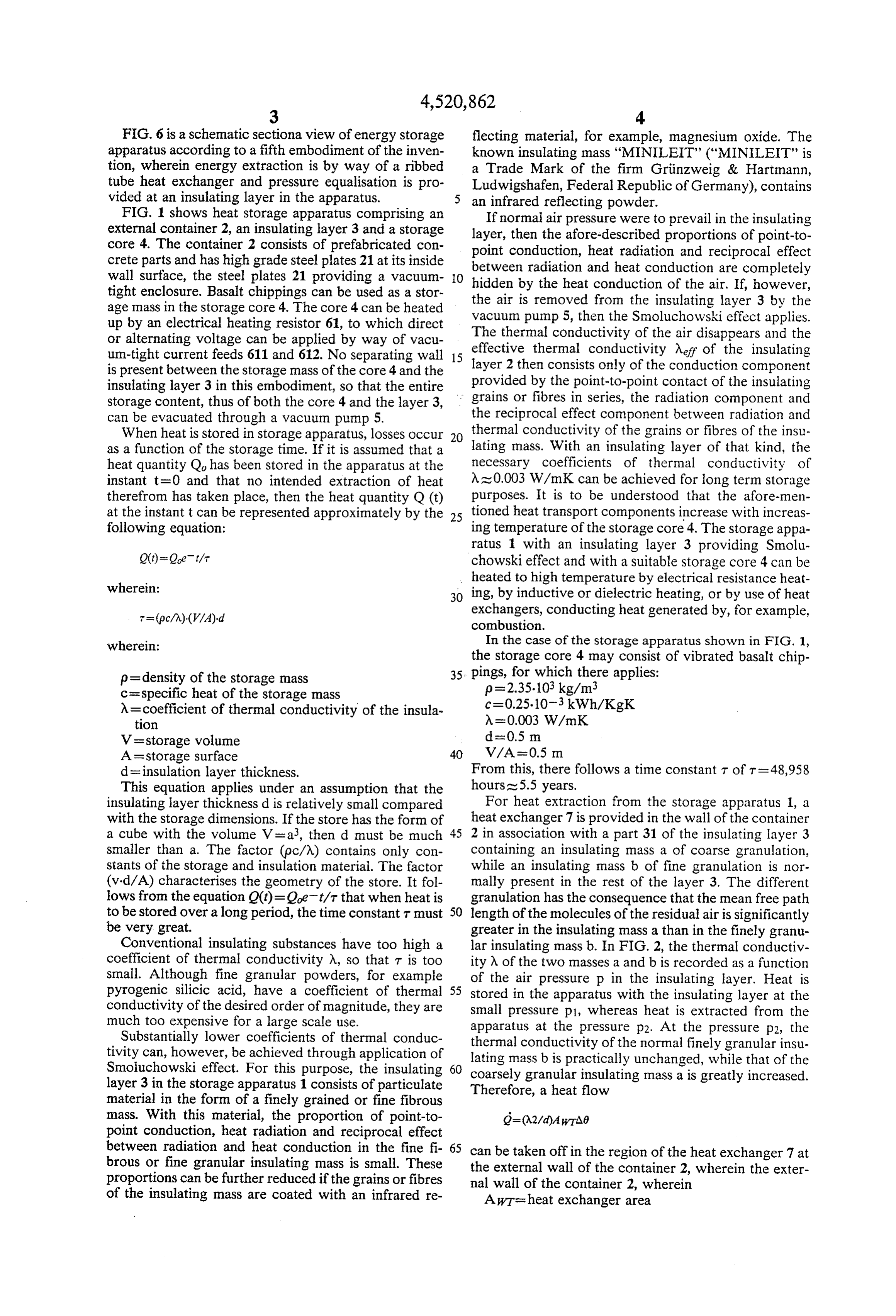
up by an electrical heating resistor 61, to which direct or alternating voltage can be applied by way of vacu The thermal conductivity of the air disappears and the effective thermal conductivity Aeff of the insulating um-tight current feeds 611 and 612. No separating wall 15 layer is present between the storage mass of the core 4 and the provided 2 then consists only of the conduction component insulating layer 3 in this embodiment, so that the entire by the point-to-point contact of the insulating storage content, thus of both the core 4 and the layer 3, grains or fibres in series, the radiation component and can be evacuated through a vacuum pump 5. the reciprocal effect component between radiation and When heat is stored in storage apparatus, losses occur 20 thermal conductivity of the grains or fibres of the insu as a function of the storage time. If it is assumed that a lating mass. With an insulating layer of that kind, the heat quantity Qo has been stored in the apparatus at the necessary coefficients of thermal conductivity of instant t=0 and that no intended extraction of heat As 0.003 W/mk can be achieved for long term storage therefrom has taken place, then the heat quantity Q (t) purposes. It is to be understood that the afore-men at the instant t can be represented approximately by the 25 tioned heat transport components increase with increas following equation: ing temperature of the storage core 4. The storage appa ratus 1 with an insulating layer 3 providing Smolu chowski effect and with a suitable storage core 4 can be heated to high temperature by electrical resistance heat 30 ing, by inductive or dielectric heating, or by use of heat exchangers, conducting heat generated by, for example, combustion.
wherein: In the case of the storage apparatus shown in FIG. 1, the storage core 4 may consist of vibrated basalt chip p = density of the storage mass 35. pings, for which there applies: c=specific heat of the storage mass p=2.35.103 kg/m.
A= coefficient of thermal conductivity of the insula c=0.25.10-3 kWh/KgK tion A=0.003 W/mk
V=storage volume das 0.5 m
A=storage surface V/A=0.5 In d = insulation layer thickness. From this, there follows a time constant t of t=48,958 This equation applies under an assumption that the hours as 5.5 years.
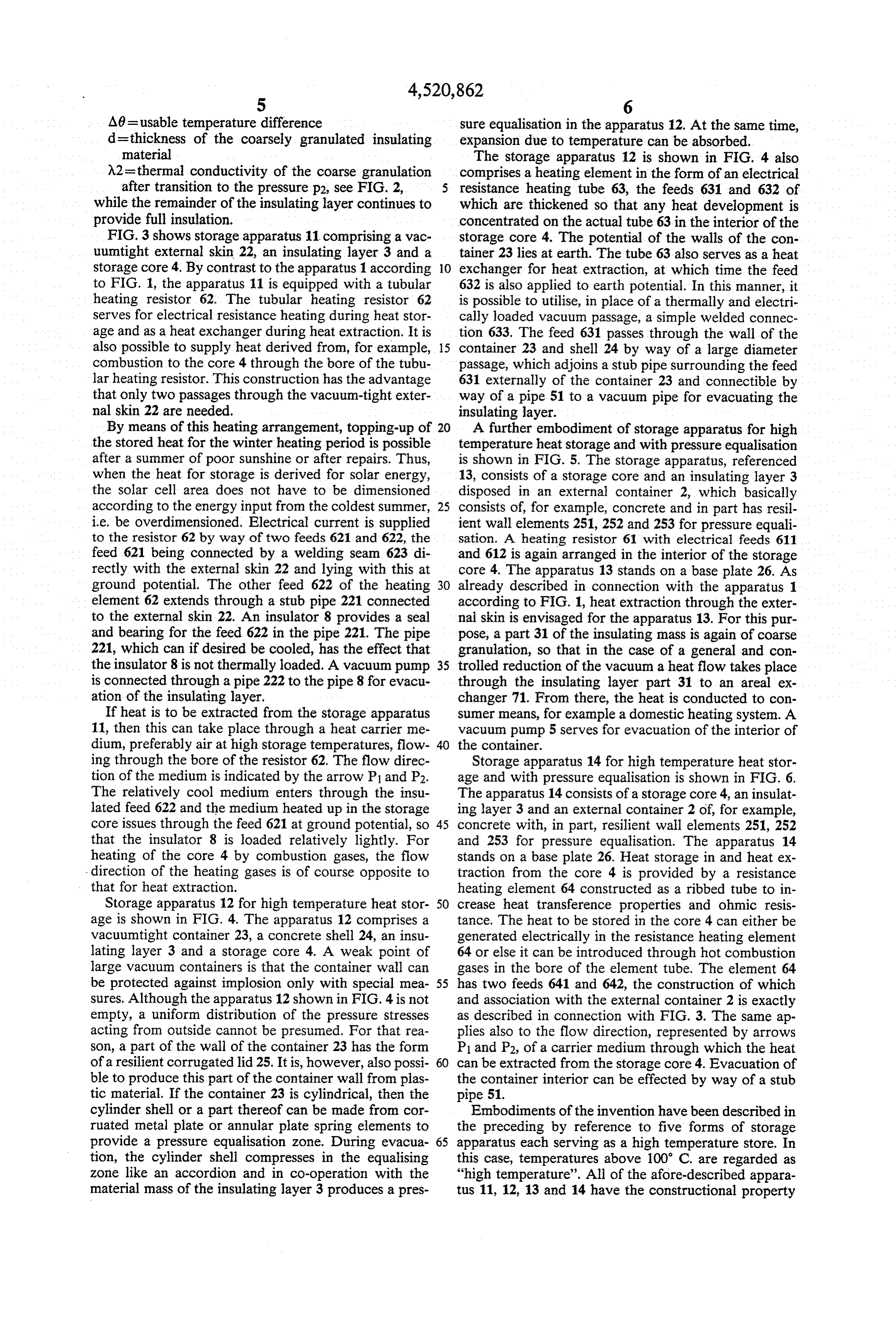
insulating layer thickness d is relatively small compared For heat extraction from the storage apparatus 1, a with the storage dimensions. If the store has the form of heat exchanger 7 is provided in the wall of the container a cube with the volume V = a, then d must be much 45 2 in association with a part 31 of the insulating layer 3 smaller than a. The factor (pc/A) contains only con containing an insulating mass a of coarse granulation, stants of the storage and insulation material. The factor while an insulating mass b of fine granulation is nor (vid/A) characterises the geometry of the store. It fol mally present in the rest of the layer 3. The different lows from the equation Q(t)=Qet/t that when heat is granulation has the consequence that the mean free path to be stored over a long period, the time constant t must 50 length of the molecules of the residual air is significantly be very great. greater in the insulating mass a than in the finely granu Conventional insulating substances have too high a lar insulating mass b. In FIG. 2, the thermal conductiv coefficient of thermal conductivity A, so that T is too ity N of the two masses a and b is recorded as a function small. Although fine granular powders, for example of the air pressure p in the insulating layer. Heat is pyrogenic silicic acid, have a coefficient of thermal 55 stored in the apparatus with the insulating layer at the conductivity of the desired order of magnitude, they are small pressure p1, whereas heat is extracted from the much too expensive for a large scale use. apparatus at the pressure p2. At the pressure p2, the Substantially lower coefficients of thermal conduc thermal conductivity of the normal finely granular insu tivity can, however, be achieved through application of lating mass b is practically unchanged, while that of the Smoluchowski effect. For this purpose, the insulating 60 coarsely layer 3 in the storage apparatus 1 consists of particulate Therefore,granular insulating massa is greatly increased. a heat flow material in the form of a finely grained or fine fibrous mass. With this material, the proportion of point-to point conduction, heat radiation and reciprocal effect between radiation and heat conduction in the fine fi 65 can be taken off in the region of the heat exchanger 7 at brous or fine granular insulating mass is small. These the external wall of the container 2, wherein the exter proportions can be further reduced if the grains or fibres nal wall of the container 2, wherein of the insulating mass are coated with an infrared re AWT's heat exchanger area
Page 7
A6= usable temperature difference sure equalisation in the apparatus 12. At the same time, d=thickness of the coarsely granulated insulating expansion due to temperature can be absorbed. material The storage apparatus 12 is shown in FIG. 4 also A2 = thermal conductivity of the coarse granulation comprises a heating element in the form of an electrical after transition to the pressure p2, see FIG. 2, resistance heating tube 63, the feeds 631 and 632 of while the remainder of the insulating layer continues to which are thickened so that any heat development is provide full insulation. concentrated on the actual tube 63 in the interior of the FIG.3 shows storage apparatus 11 comprising a vac storage core 4. The potential of the walls of the con uumtight external skin 22, an insulating layer 3 and a tainer 23 lies at earth. The tube 63 also serves as a heat storage core 4. By contrast to the apparatus 1 according 10 exchanger for heat extraction, at which time the feed to FIG. 1, the apparatus 11 is equipped with a tubular 632 is also applied to earth potential. In this manner, it heating resistor 62. The tubular heating resistor 62 is possible to utilise, in place of a thermally and electri serves for electrical resistance heating during heat stor cally loaded vacuum passage, a simple welded connec age and as a heat exchanger during heat extraction. It is tion 633. The feed 631 passes through the wall of the also possible to supply heat derived from, for example, 15 container 23 and shell 24 by way of a large diameter combustion to the core 4 through the bore of the tubu passage, which adjoins a stub pipe surrounding the feed lar heating resistor. This construction has the advantage 631 externally of the container 23 and connectible by that only two passages through the vacuum-tight exter way of a pipe 51 to a vacuum pipe for evacuating the nal skin 22 are needed. insulating layer.
By means of this heating arrangement, topping-up of 20 A further embodiment of storage apparatus for high the stored heat for the winter heating period is possible temperature heat storage and with pressure equalisation after a summer of poor sunshine or after repairs. Thus, is shown in FIG. 5. The storage apparatus, referenced when the heat for storage is derived for solar energy, 13, consists of a storage core and an insulating layer 3 the solar cell area does not have to be dimensioned disposed in an external container 2, which basically according to the energy input from the coldest summer, 25 consists of, for example, concrete and in part has resil i.e. be overdimensioned. Electrical current is supplied ient wall elements 251, 252 and 253 for pressure equali to the resistor 62 by way of two feeds 621 and 622, the sation. A heating resistor 61 with electrical feeds 611 feed 621 being connected by a welding seam 623 di and 612 is again arranged in the interior of the storage rectly with the external skin 22 and lying with this at core 4. The apparatus 13 stands on a base plate 26. As ground potential. The other feed 622 of the heating 30 already described in connection with the apparatus 1 element 62 extends through a stub pipe 221 connected according to FIG. 1, heat extraction through the exter to the external skin 22. An insulator 8 provides a seal nal skin is envisaged for the apparatus 13. For this pur and bearing for the feed 622 in the pipe 221. The pipe pose, a part 31 of the insulating mass is again of coarse 221, which can if desired be cooled, has the effect that granulation, so that in the case of a general and con the insulator 8 is not thermally loaded. A vacuum pump 35 trolled reduction of the vacuum a heat flow takes place is connected through a pipe 222 to the pipe 8 for evacu through the insulating layer part 31 to an areal ex ation of the insulating layer. changer 71. From there, the heat is conducted to con If heat is to be extracted from the storage apparatus sumer means, for example a domestic heating system. A 11, then this can take place through a heat carrier me vacuum pump 5 serves for evacuation of the interior of dium, preferably air at high storage temperatures, flow 40 the container.
ing through the bore of the resistor 62. The flow direc Storage apparatus 14 for high temperature heat stor tion of the medium is indicated by the arrow P1 and P2. age and with pressure equalisation is shown in FIG. 6. The relatively cool medium enters through the insu The apparatus 14 consists of a storage core 4, an insulat lated feed 622 and the medium heated up in the storage ing layer 3 and an external container 2 of, for example, core issues through the feed 621 at ground potential, so 45 concrete with, in part, resilient wall elements 251, 252 that the insulator 8 is loaded relatively lightly. For and 253 for pressure equalisation. The apparatus 14 heating of the core 4 by combustion gases, the flow stands on a base plate 26. Heat storage in and heat ex direction of the heating gases is of course opposite to traction from the core 4 is provided by a resistance that for heat extraction. heating element 64 constructed as a ribbed tube to in Storage apparatus 12 for high temperature heat stor 50 crease heat transference properties and ohmic resis age is shown in FIG. 4. The apparatus 12 comprises a tance. The heat to be stored in the core 4 can either be vacuumtight container 23, a concrete shell 24, an insu generated electrically in the resistance heating element lating layer 3 and a storage core 4. A weak point of 64 or else it can be introduced through hot combustion large vacuum containers is that the container wall can gases in the bore of the element tube. The element 64 be protected against implosion only with special mea 55 has two feeds 641 and 642, the construction of which sures. Although the apparatus 12 shown in FIG. 4 is not and association with the external container 2 is exactly empty, a uniform distribution of the pressure stresses as described in connection with FIG. 3. The same ap acting from outside cannot be presumed. For that rea plies also to the flow direction, represented by arrows son, a part of the wall of the container 23 has the form P1 and P2, of a carrier medium through which the heat of a resilient corrugated lid 25. It is, however, also possi 60 can be extracted from the storage core 4. Evacuation of ble to produce this part of the container wall from plas the container interior can be effected by way of a stub tic material. If the container 23 is cylindrical, then the pipe 51.
cylinder shell or a part thereof can be made from cor Embodiments of the invention have been described in ruated metal plate or annular plate spring elements to the preceding by reference to five forms of storage provide a pressure equalisation zone. During evacua 65 apparatus each serving as a high temperature store. In tion, the cylinder shell compresses in the equalising this case, temperatures above 100° C. are regarded as zone like an accordion and in co-operation with the "high temperature'. All of the afore-described appara material mass of the insulating layer 3 produces a pres tus 11, 12, 13 and 14 have the constructional property
Page 8
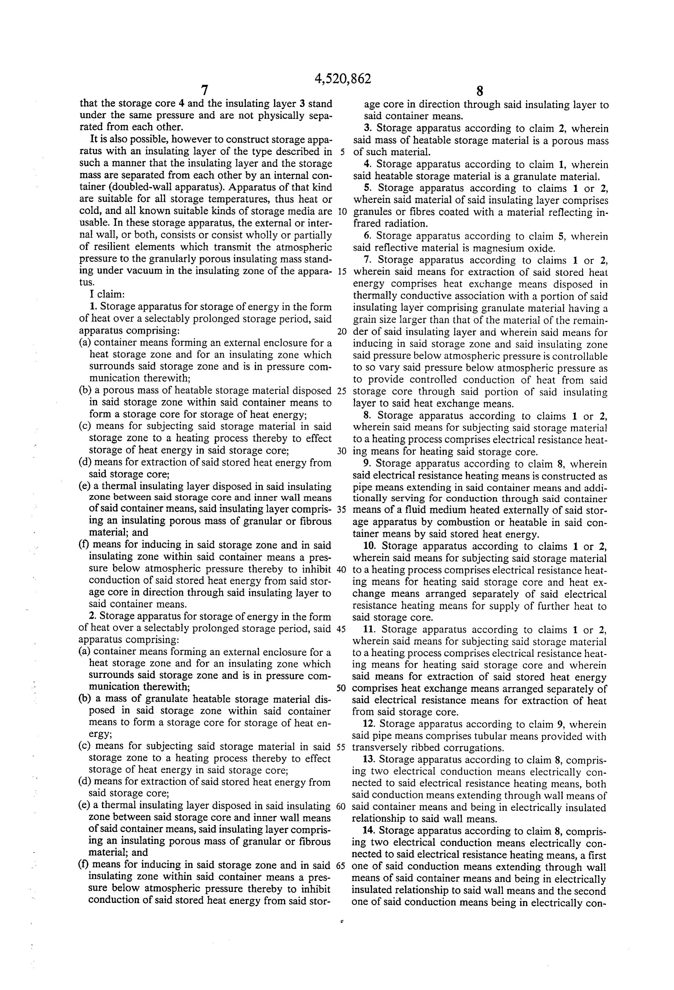
that the storage core 4 and the insulating layer 3 stand age core in direction through said insulating layer to under the same pressure and are not physically sepa said container means.
rated from each other. 3. Storage apparatus according to claim 2, wherein It is also possible, however to construct storage appa said mass of heatable storage material is a porous mass ratus with an insulating layer of the type described in of such material.
such a manner that the insulating layer and the storage 4. Storage apparatus according to claim 1, wherein mass are separated from each other by an internal con said heatable storage material is a granulate material. tainer (doubled-wall apparatus). Apparatus of that kind 5. Storage apparatus according to claims 1 or 2, are suitable for all storage temperatures, thus heat or wherein said material of said insulating layer comprises cold, and all known suitable kinds of storage media are O granules or fibres coated with a material reflecting in usable. In these storage apparatus, the external or inter frared radiation.
nal wall, or both, consists or consist wholly or partially 6. Storage apparatus according to claim 5, wherein of resilient elements which transmit the atmospheric said reflective material is magnesium oxide. pressure to the granularly porous insulating mass stand 7. Storage apparatus according to claims 1 or 2, ing under vacuum in the insulating Zone of the appara 15 wherein said means for extraction of said stored heat tuS. energy comprises heat exchange means disposed in I claim: thermally conductive association with a portion of said 1. Storage apparatus for storage of energy in the form insulating layer comprising granulate material having a of heat over a selectably prolonged storage period, said grain size larger than that of the material of the remain apparatus comprising: 20 der of said insulating layer and wherein said means for (a) container means forming an external enclosure for a inducing in said storage Zone and said insulating Zone heat storage zone and for an insulating zone which said pressure below atmospheric pressure is controllable surrounds said storage Zone and is in pressure com to so vary said pressure below atmospheric pressure as munication therewith; to provide controlled conduction of heat from said (b) a porous mass of heatable storage material disposed 25 storage core through said portion of said insulating in said storage zone within said container means to layer to said heat exchange means.
form a storage core for storage of heat energy; 8. Storage apparatus according to claims 1 or 2, (c) means for subjecting said storage material in said wherein said means for subjecting said storage material storage Zone to a heating process thereby to effect to a heating process comprises electrical resistance heat storage of heat energy in said storage core; 30 ing means for heating said storage core. (d) means for extraction of said stored heat energy from 9. Storage apparatus according to claim 8, wherein said storage core; said electrical resistance heating means is constructed as (e) a thermal insulating layer disposed in said insulating pipe means extending in said container means and addi zone between said storage core and inner wall means tionally serving for conduction through said container of said container means, said insulating layer compris 35 means of a fluid medium heated externally of said stor ing an insulating porous mass of granular or fibrous age apparatus by combustion or heatable in said con material; and tainer means by said stored heat energy. (f) means for inducing in said storage zone and in said 10. Storage apparatus according to claims 1 or 2, insulating Zone within said container means a pres wherein said means for subjecting said storage material sure below atmospheric pressure thereby to inhibit to a heating process comprises electrical resistance heat conduction of said stored heat energy from said stor ing means for heating said storage core and heat ex age core in direction through said insulating layer to change means arranged separately of said electrical said container means. resistance heating means for supply of further heat to 2. Storage apparatus for storage of energy in the form said storage core.
of heat over a selectably prolonged storage period, said 45 11. Storage apparatus according to claims 1 or 2, apparatus comprising: wherein said means for subjecting said storage material (a) container means forming an external enclosure for a to a heating process comprises electrical resistance heat heat storage Zone and for an insulating zone which ing means for heating said storage core and wherein surrounds said storage zone and is in pressure com said means for extraction of said stored heat energy munication therewith; 50 comprises heat exchange means arranged separately of (b) a mass of granulate heatable storage material dis said electrical resistance means for extraction of heat posed in said storage zone within said container from said storage core.
means to form a storage core for storage of heat en 12. Storage apparatus according to claim 9, wherein ergy; said pipe means comprises tubular means provided with (c) means for subjecting said storage material in said 55 transversely ribbed corrugations. storage Zone to a heating process thereby to effect 13. Storage apparatus according to claim 8, compris storage of heat energy in said storage core; ing two electrical conduction means electrically con (d) means for extraction of said stored heat energy from nected to said electrical resistance heating means, both said storage core; said conduction means extending through wall means of (e) a thermal insulating layer disposed in said insulating 60 said container means and being in electrically insulated Zone between said storage core and inner wall means relationship to said wall means.
of said container means, said insulating layer compris 14. Storage apparatus according to claim 8, compris ing an insulating porous mass of granular or fibrous ing two electrical conduction means electrically con material; and nected to said electrical resistance heating means, a first (f) means for inducing in said storage zone and in said 65 one of said conduction means extending through wall insulating zone within said container means a pres means of said container means and being in electrically sure below atmospheric pressure thereby to inhibit insulated relationship to said wall means and the second conduction of said stored heat energy from said stor one of said conduction means being in electrically con
Page 9
ductive relationship to said wall means, wherein said mitting the passage of infrared radiation to heat said storage core.
second one of said conduction means is at a higher 16. Storage apparatus according to claims 1 or 2, temperature than said first one of said conduction wherein said means for extraction of said stored heat e2S. energy comprises window means for permitting the 15. Storage apparatus according to claims 1 or 2, passage of infrared radiation to extract heat from said wherein said means for subjecting said storage material storage core, and generating means operable by the extracted heat to generate electric current.
to a heating process comprises window means for per sk k l k sk
Provenance
- Collection
- Cited prior art
- Original PDF
- patentimages.storage.googleapis.com →
- Filed
- 1983-02-08
- Pages
- 9
- Method
- pdftotext (the PDF's own text layer) + pdftoppm 300dpi page scans
- Source
- Google Patents bibliographic record
- Granted
- 1985-06-04
- Inventors
- Walter Helmbold
- Transcribed from
- patentimages.storage.googleapis.com →