patent · US3722445
Underwater molten salt heat storage boiler
27 March 1973
Page 1 — bibliographic record
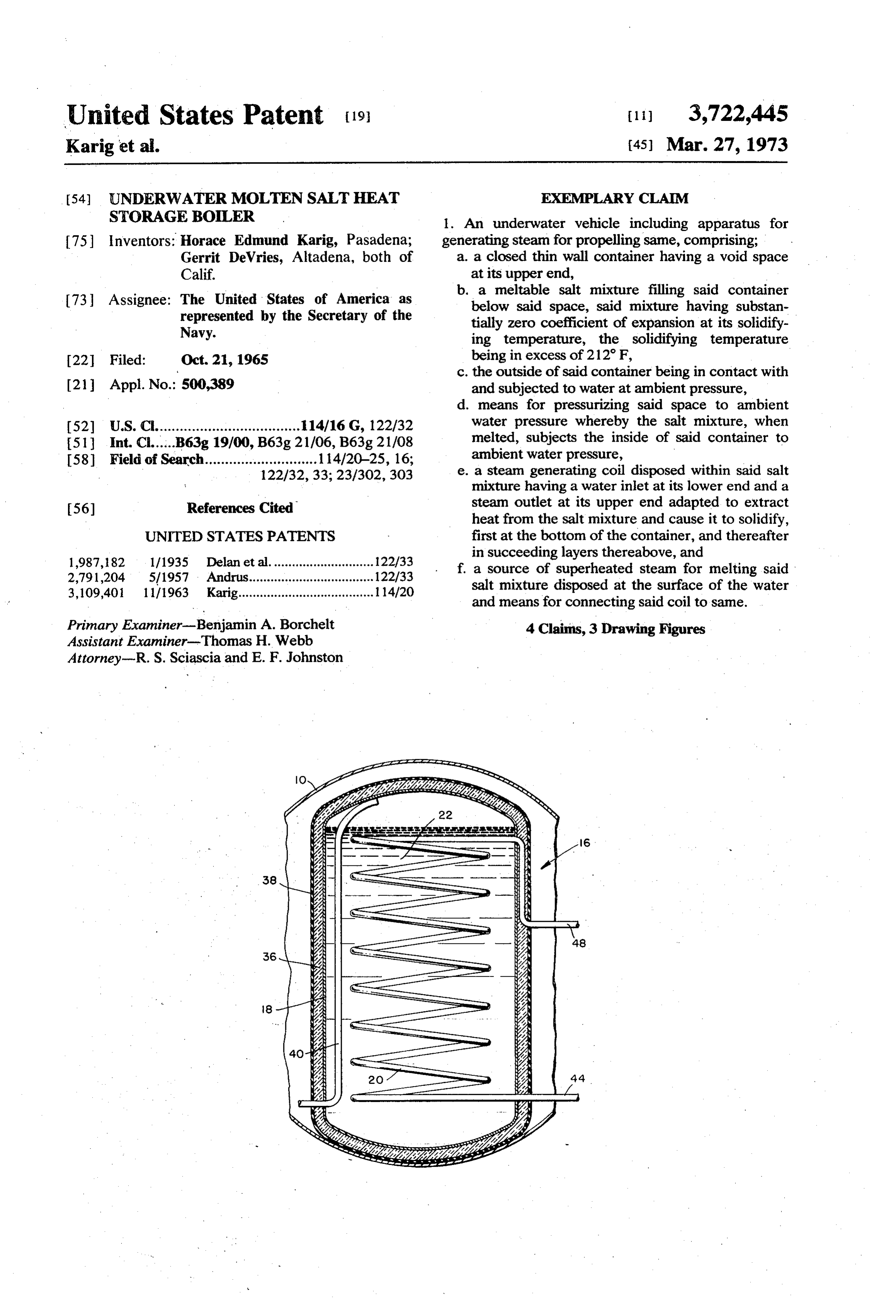
United States Patent (19) (11) 3,722,445 Karig et al. (45) Mar. 27, 1973 54) UNDERWATERMOLTEN SALT HEAT EXEMPLARY CLAM STORAGE BOLER . An underwater vehicle including apparatus for 75 Inventors: Horace Edmund Karig, Pasadena; generating steam for propelling same, comprising; Gerrit DeVries, Altadena, both of a. a closed thin wall container having a void space Calif. at its upper end,
Assignee: The United States of America as b. a meltable salt mixture filling said container 73 below said space, said mixture having substan represented by the Secretary of the tially zero coefficient of expansion at its solidify Navy. ing temperature, the solidifying temperature 22 Filed: Oct. 21, 1965 being in excess of 212 F, c. the outside of said container being in contact with 21 Appl. No.: 500,389 and subjected to water at ambient pressure, d. means for pressurizing said space to ambient (52) U.S.C.................................... 114/16 G, 122/32 water pressure whereby the salt mixture, when 51 Int. Cl......B63g 19/00, B63g 21/06, B63g 21/08 melted, subjects the inside of said container to 58 Field of Search............................ 114/20-25, 16; ambient water pressure, 122/32, 33; 23/302,303 e. a steam generating coil disposed within said salt mixture having a water inlet at its lower end and a 56) References Cited steam outlet at its upper end adapted to extract heat from the salt mixture and cause it to solidify,
UNITED STATES PATENTS first at the bottom of the container, and thereafter 1987, 182 1/1935 Delan et al............................ 122/33 in succeeding layers thereabove, and 2,791,204 5/1957 Andrus................................... 122/33 f. a source of superheated steam for melting said 3,109,401 11/1963 Karig...................................... 114/20 salt mixture disposed at the surface of the water and means for connecting said coil to same.
Primary Examiner-Benjamin A. Borchelt 4 Claims, 3 Drawing Figures Assistant Examiner-Thomas H. Webb
Attorney-R. S. Sciascia and E. F. Johnston
Page 2
Drawing sheet — no readable text.
Page 3
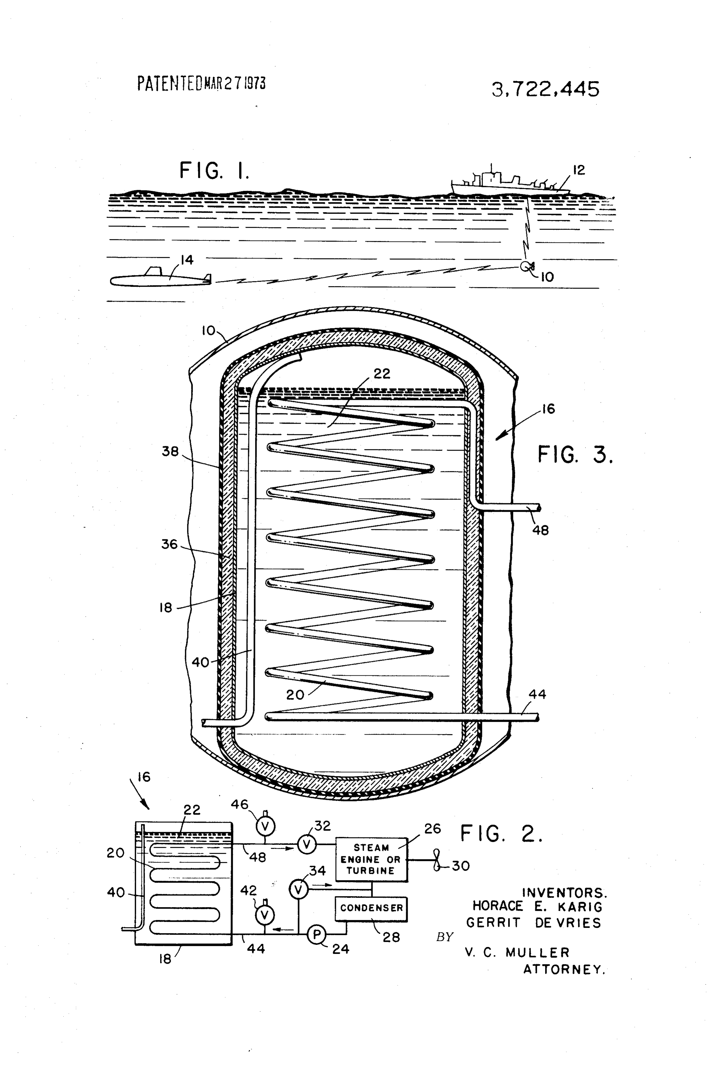
UNDERWATERMOLTEN SALT HEAT STORAGE Referring now to the drawing, and first to FIG. , an BOLER exemplary environment of the invention is illustrated as The invention described herein may be manufac contained within an underwater vehicle 10 which is tured and used by or for the Government of the United self-propelled and follows the course of surface ship 12 States of America for governmental purposes without at a desired depth of submergence and which detects the payment of any royalties thereon or therefor. the presence of a submarine 14, telemetering such in This invention relates to underwater vehicle propul formation to the surface ship, all as previously referred sion systems and more particularly to improvements in tO.
steam boilers for use with the same. Referring now to FIG. 2, vehicle 10 contains a boiler in the art of anti-submarine warfare a recent concept O 16 comprising a container 18 and a steam generating contemplates the use of an unmanned underwater vehi coil 20 within the container, the coil being submerged cle which is self-propelled at considerable depth in a salt mixture 22 to be hereinafter described in more beneath a moving surface ship and which is provided detail.
with suitable sonar apparatus for detecting the location In operation, feed water is delivered to the coil by a of enemy submarines. The information received by the 15 pump 24, producing steam, which is delivered to a vehicle is telemetered to the surface ship which may steam engine 26, thence to a condenser 28 and back to then launch a suitable missile, such as ASROC, for the pump for recirculation to the boiler. The engine is destroying the submarine. It is highly desirable that the connected to a suitable propeller or pump-jet rotor 30 underwater vehicle have as long an operating range as for propelling the vehicle. A valve 32, under suitable possible to thus minimize the intervals at which it is control, may be provided to control the speed and brought to the surface, under command from the sur power delivered by the engine and a by-pass or relief face ship, for recharging its energy source. valve 34 may be provided to control the boiler steam The underwater drone vehicle is substantially spheri generation rate and pressure.
cal in shape and is slightly positively buoyant, being Referring now to FIG. 3, container 18 may be of any maintained at desired depth by its forward motion and 25 suitable shape, such as cylindrical, which will fit within suitable hydrodynamic surfaces. Conventional rudders the generally spherical vehicle 10. Container 18 is are provided, controlled by the surface ship, for completely surrounded by porous heat insulation 36, maneuvering it along a course substantially directly the outer surface of which is completely covered by a below the course of the surface ship. Except for certain sonar, telemetering, and propulsion components, the 30 flexible water bag 38, such as rubber, which prevents sea from entering the insulation and destroying its in spherical hull is flooded with sea water at ambient pres sulating characteristics. To simplify the disclosure, coil sure thus permitting the use of a thin wall unstressed 20 is illustrated in the form of a single cylindrical helix, hull.
however, in actual practice
Various energy sources for propelling the vehicle are preferably be more uniformly distributed the coil 20 would conceivable, rechargeable batteries probably being one 35 the throughout mass of the salt bed 22, to thus uniformly of the most simple forms. Batteries, however, suffer the heat content. One such construction comprises extract its disadvantages of low energy density, long recharging a plu rality of parallel spaced flat coils, each in the form of an time and limited cycles of recharging. Replenished Archimedean sources of energy, such as fuels or propellants, while 40 necting with the spiral, the inner end of one spiral con having higher energy densities, have certain disad reduce the overallouter end of an adjacent spiral. To vantages including difficulties of control of combustion the coil, a plurality of coilsand length pressure drop through rates, heavy stressed combustion chambers and the provided, feed water being delivered to relation in parallel may be a common inlet like, buoyancy changes due to depletion of fuel and generation of noise by exhaust gases. and steam being delivered to a common outlet. A pres One of the objects of this invention is to provide an sure equalizing tube 40 is provided, one end of which
energy source for use in a self-propelled underwater terminates in the space above the saltbed 22, the other vehicle which may be quickly and readily recharged at end communicating with ambient sea water, such as the intervals by an available heat source on a surface ship. water which floods the inside of the vehicle. A valve 42 Another object is to pressure balance the energy connects with the feed water conduit 44 and a like source to ambient water pressure whereby the use of valve 46 connects with the steam delivery conduit 48. heavy chambers and the like is obviated. In the operation of the vehicle and its boiler, it will be A further object is to provide a heat source, in the assumed that the vehicle is at the surface of the water form of a heat sink, of meltable salts having high heat or on the deck of surface vessel 12 and that the saltbed content per unit of weight and volume. 22 is solidified. Suitable conduits are connected to A still further object is to provide a heat sink in the 55 valves 42, 46, which are connected to a recirculating form of a specific mixture of salts which have substan source of superheated steam which is available on the tially zero coefficient of expansion when they change surface ship. The steam is passed through coil 20 for a from liquid to solid state. sufficient period to melt the salt bed and raise it to a Still further objects, advantages and salient features desired temperature above its melting temperature. will become more apparent from the description to fol The steam conduits are then disconnected and valves low, the appended claims, and the accompanying draw 42, 46 closed. The vehicle is now ready for operation. ing, in which: Pump 24 is next actuated to supply feed water to the FIG. 1 illustrates an environment of the invention; coil and the generated steam operates the engine to FIG. 2 is a schematic of the essential components of 65 propel the vehicle to its desired position below the sur a steam powerplant system, and face ship. As the vehicle descends, ambient water en FIG. 3 is a cross section of a steam boiler, illustrated ters tube 40 and tends to rise into the space above the schematically in FIG.2. salt bed. Tube 40, however, is disposed within the hot
Page 4
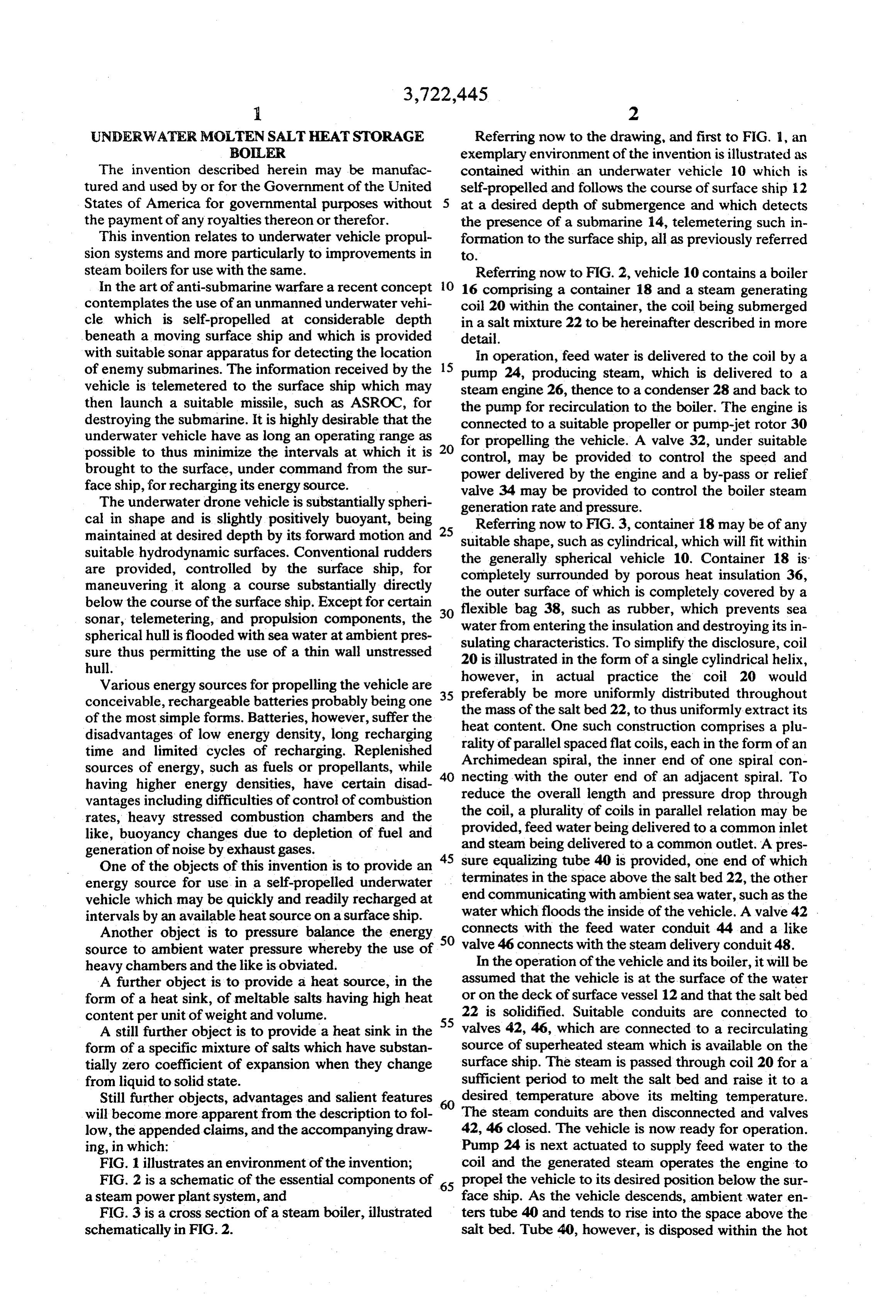
salt bed and as the water rises steam is formed which obviate this possibility the top of the salt bed may be enters the space above the salt bed. As will be ap isolated from tube 40 by the provision of a piston, bel parent, the pressure of the steam above the salt bed will lows or diaphragm extending across container 18. balance the ambient pressure on the outside of the salt Thus, the salt will be contained in a chamber below the container at all depths, and, since the salt bed is now top end of tube 40, and tube 40 will communicate with liquified it will also be at ambient sea pressure. There is an adjacent chamber, pressure in tube 40 being trans thus no tendency to collapse the thin wall salt con mitted to the salt bed through the separating wall tainer. The vehicle continues to be propelled by the formed by the piston, bellows, or diaphragm. heat content of the salt bed for the desired interval, ex Obviously many modifications and variations of the tracting the heat of the liquid salt above its solidifying 10 present invention are possible in the light of the above temperature, its latent heat of solidification and the the scope ofIt the teachings. is therefore to be understood that within appended claims the invention may be heat of the solid salt to a desired temperature below the practiced otherwise than as specifically described. temperature of solidification. What is claimed is:
The boiler should be maintained in substantially 1. An underwater vehicle including apparatus for upright position, as illustrated, and the feed water 15 generating steam for propelling same, comprising; should enter at the lower end of the coil, emerging as a. a closed thin wall container having a void space at steam from the upper end. With such arrangement, the its upper end, salt bed will begin to solidify at the bottom, continuing to solidify in successive layers upwardly. The voids in 20 b. said a meltable salt mixture filling said container below space, said mixture having substantially zero any solidifying layer will be filled by the pressurized coefficient of expansion at its solidifying tempera liquid salt above it and, upon complete solidification of ture, the solidifying temperature being in excess of a layer it becomes a rigid mass supporting the container 212°F, against collapse. . . the outside of said container being in contact with It is thus apparent that the rate of heat transfer from and subjected to water at ambient pressure, the bed to the feed water and steam is greater at a lower 25 . . means for pressurizing said space to ambient water portion of the bed than at an upper portion, thus effect pressure whereby the salt mixture, when melted, ing continuous upward solidification of the bed, any subjects the inside of said container to ambient portion above the solidified portion remaining liquid, water pressure, until finally the top liquid portion also solidifies. Since 30 . . a steam generating coil disposed within said salt the top and last liquid portion is still at a relatively high mixture having a water inlet at its lower end and a temperature, high temperature steam can be generated steam outlet at its upper end adapted to extract throughout the entire solidification process of the bed. heat from the salt mixture and cause it to solidify, An important feature of the invention is to prevent first at the bottom of the container, and thereafter increase of volume of the saltbed when it changes from 35 in succeeding layers thereabove, and liquid to solid. Expansion, for example, would stress the f. a source of superheated steam for melting said salt container in tension tending to rupture it. Also, but less mixture disposed at the surface of the water and important, an undesired crushing force would be ap means for connecting said coil to same. plied to the steam coil. The preferred salt bed material 2. Apparatus in accordance with claim 1, including comprises a mixture of 60 to 90% LiOH and 40% to 40 porous heat insulation surrounding said container, and 10% LiF by weight which is non-reactive with water or means surrounding the heat insulation for preventing air. About 80% LiOH and 20% LiF is ideal, providing a sea water from penetrating the insulation. mixture with substantially zero coefficient of expansion 3. Apparatus in accordance with claim 1 wherein during solidification. The melting point of such mixture said means for pressurizing said space comprises a con ranges between 750-810F thus permitting the use of 45 duit having one end communicating with ambient superheated steam for recharging. Another mixture water and its other end communicating with said space, having similar freezing characteristics comprises about an intermediate portion being in heat exchange relation 50% of LiF and 50% of BeF, by weight. with said salt mixture and adapted to generate steam The steam pressure in the coil may be as desired. If from ambient water for pressurizing said space to am such pressure is the same as ambient pressure there will SO bient water pressure.
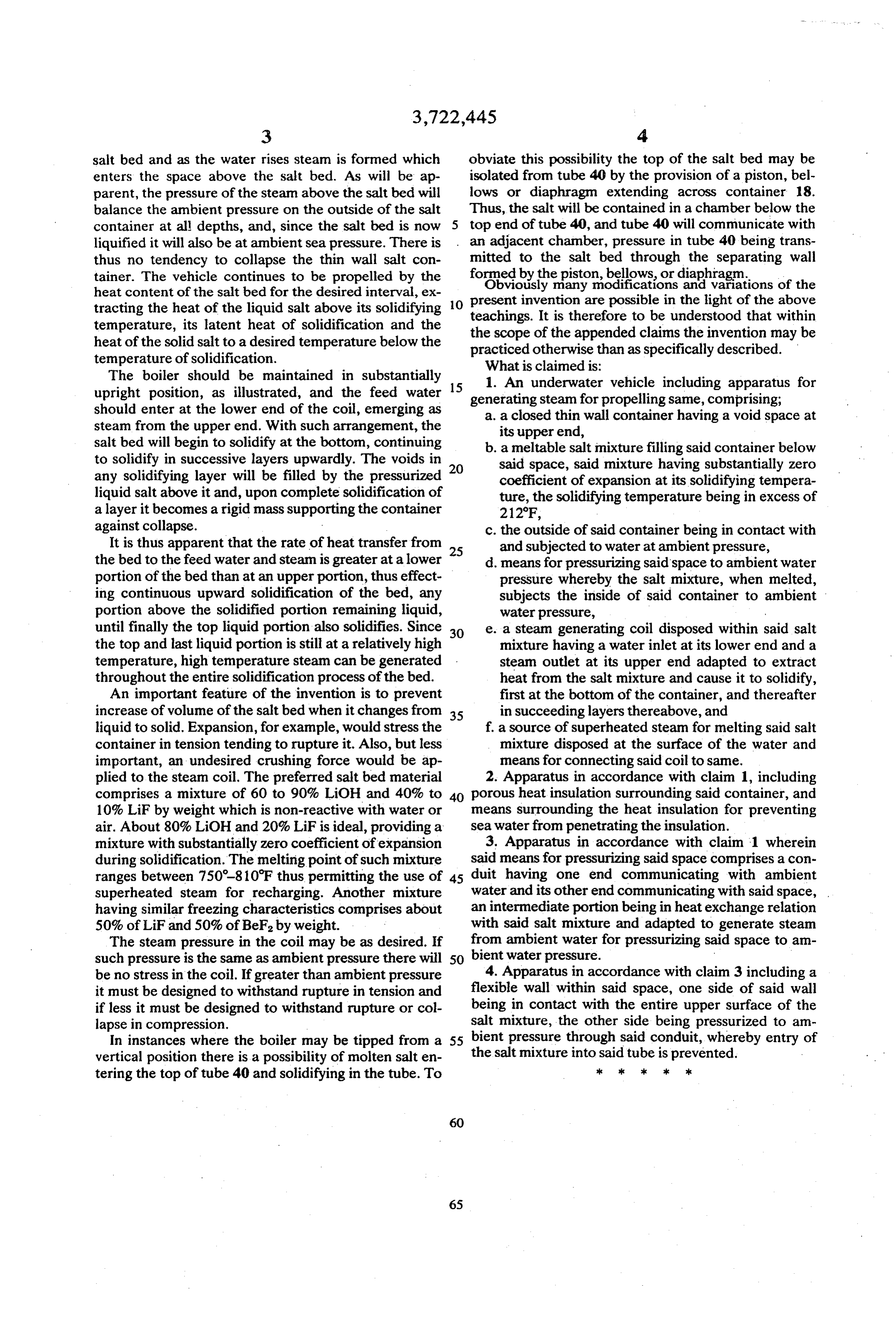
be no stress in the coil. If greater than ambient pressure 4. Apparatus in accordance with claim 3 including a it must be designed to withstand rupture in tension and flexible wall within said space, one side of said wall if less it must be designed to withstand rupture or col being in contact with the entire upper surface of the lapse in compression. salt mixture, the other side being pressurized to am In instances where the boiler may be tipped from a 55 bient pressure through said conduit, whereby entry of vertical position there is a possibility of molten salt en the salt mixture into said tube is prevented. tering the top of tube 40 and solidifying in the tube. To sk xk k k is
Provenance
- Collection
- Cited prior art
- Original PDF
- patentimages.storage.googleapis.com →
- Filed
- 1965-10-21
- Pages
- 4
- Method
- pdftotext (the PDF's own text layer) + pdftoppm 300dpi page scans
- Source
- Google Patents bibliographic record
- Granted
- 1973-03-27
- Inventors
- H Karig; Vries G De; US Department of Navy
- Transcribed from
- patentimages.storage.googleapis.com →